


dudaindc
-
Posts
12 -
Joined
-
Last visited
Content Type
Forums
Events
Gallery
Posts posted by dudaindc
-
-
On 6/4/2023 at 3:57 PM, lothian said:

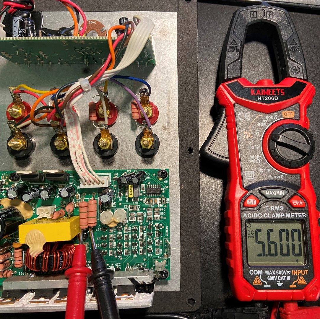
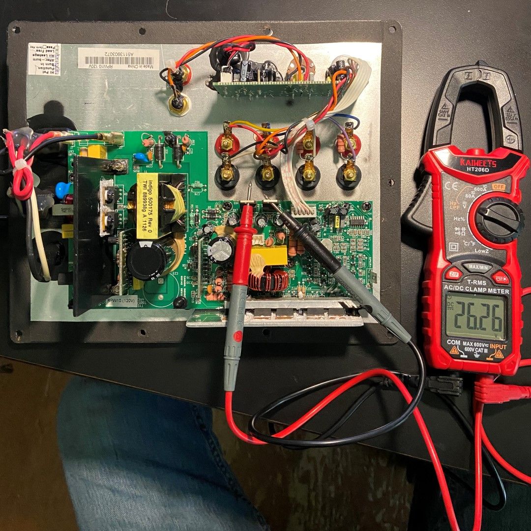
I'm t'shooting a non-working RPW10 PCB. I do not own a scope; just a DMM.
- I get no sound from the speaker, no hum nor the power-on thump.
- Power LED lights and the fuse tests OK. Fuse tests OK and does not blow when amp is powered on.
- Visually, the PCB is excellent: no smoked traces, lifted pads, blown caps a/o burned resistors.
- No odor of burnt electronics.
- I get ~26.3vDC across the voltage regulators.
- I get ~5.6vDC across the two large resistors (volume at min.).
- With board unplugged, I see normal cap drain-down: voltage drains to zero volts when measured across the voltage regulators.
Thus the usual culprits all appear to be normal.
What do I need to test next?
I would check the pre-amp board output when feeding a test signal into one of the RCA input jacks.
I had at least 2 boards with defective volume pots.
Just a thought...
-
On 3/24/2022 at 2:46 AM, Hatsune Miku said:
I have the rw-10d and the last 2 days have been attempting to check everything. I decided I'd check the 5v reg today and apply 5v to the left side. Success! The 5v reg was dead. For some reason I decided to apply 15v to the right side to verify it was dead. Now the 5v rail is shorted to gnd after the regulator. I snipped the output leg of the regulator so that's not where the short is. What else could have been shorted? I unplugged the ribbon to the plate amp. So the board with the 5v reg has a short somewhere.
My power supply was limited to .2a
The diode above the 5v reg isn't shorted but doesn't measure .6v anymore it's 1.2v now. Maybe it's always been that way, I didnt check it before.
I had a similar issue and suspected that the volume control chip was dead.
Once I removed it, the short was gone.
After replacing the chip, the amp came back to life.
Good luck with your repair.
-
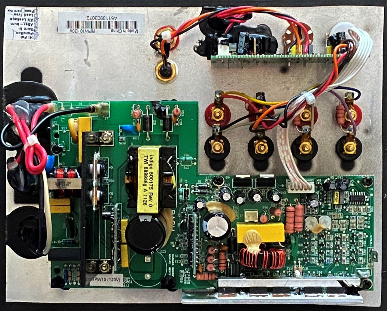
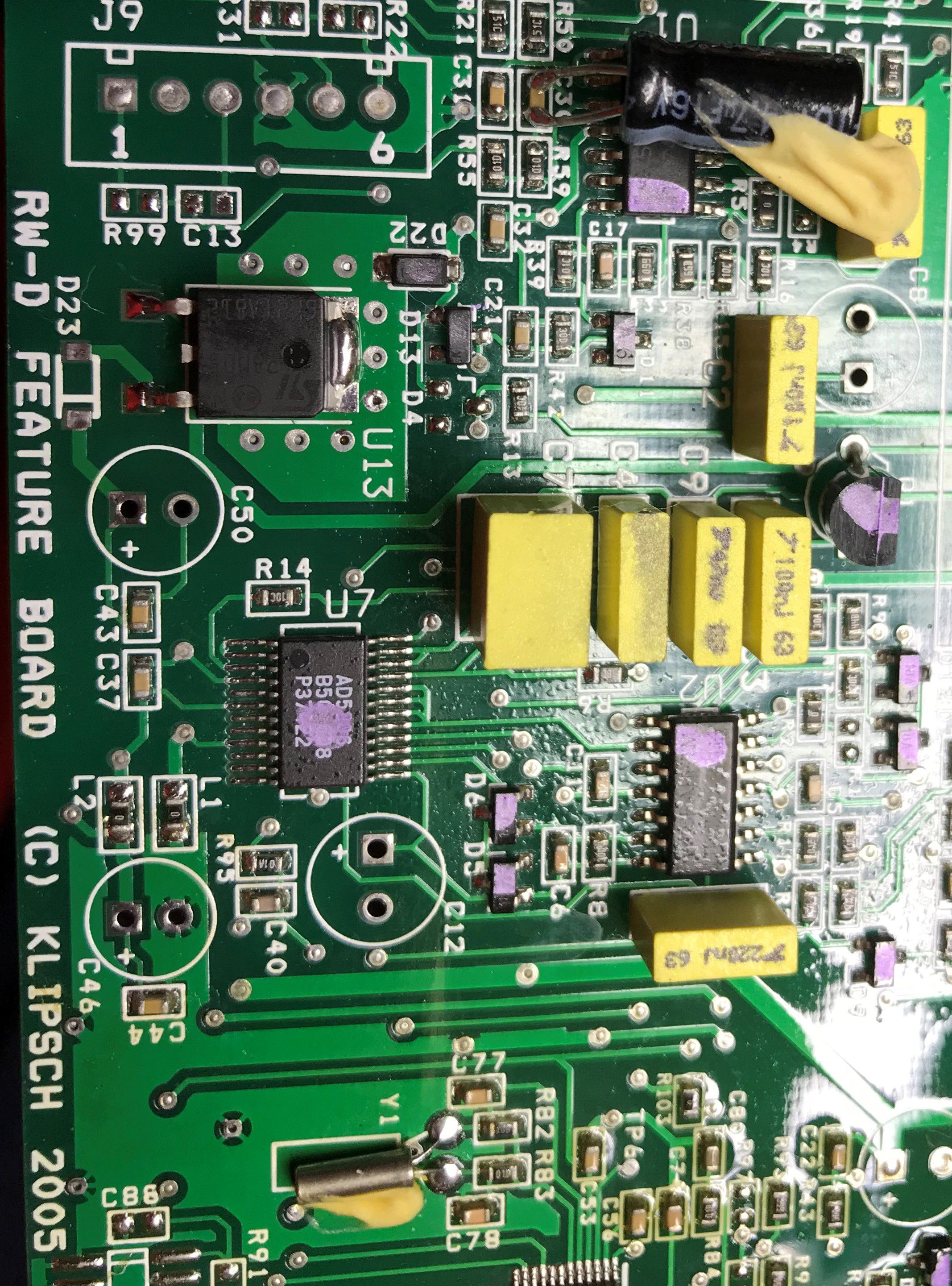
I have two (2) RW10-D plate amps that are driving me nuts... without the schematics, I am basically stuck.
For both amps, all caps have been replaced with high-quality ones and not a trace of the yellow glue.The first one works fine (i.e., responds to all commands and I get sound) but just the display does not light up. Already changed the display, cable, etc., but nothing seems to solve the issue. Measuring the voltages in the flat cable pins I found that these do not match what I measured on other similar amps... it seems that logic/polarity is reversed for most pins.
The second one also works fine but I need to push the volume all the way up - it seems that the gain structure is wrong (e.g., one op-amp may not be working as it should).I thought it could be the digital volume chip but that is not easy to solder (at least for me) and I want to explore other possible causes for the issue.
Any thoughts or suggestions?
Thanks in advance!
-
On 12/19/2020 at 4:21 AM, ngen33r said:
AWESOME - THANK YOU!
-
Awesome - thanks for doing that!
-
23 hours ago, Kaare said:
I have a Klipsch "SSUB10+05360296" (per the sticker) plate amp assy that is not working, not burnt, no visible damage, that I will give to someone who is willing to pay shipping from Seattle area. It does get a rumbling sound to the speaker but I am unwilling to spend the hours and $$ to fix it. Picture upon request.
I will take you up on the offer - thanks!
Please send me payment details.
🙂
-
On 4/29/2020 at 4:28 PM, ngen33r said:
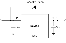
Thinking about this more, that might not be a zener. Typically a zener is not placed across an LDO like that I am guessing that is a protection diode.
https://www.onsemi.com/pub/Collateral/MBR0540T1-D.PDF

I agree and believe this to be a Schottky, but the diagram only applies to the new boards and not to the older ones.
For the latter, the diode is in series with the output of the regulator as if trying to create a 4.3V for the volume control chip.
I posted pictures of both (see previous post), but I took a better one.
-
19 hours ago, ngen33r said:
The techs there have cross referenced me parts that were not correct and have caused hundreds in extra damage. I will never make that mistake again even if it was bad luck.
Do some homework and use the available resources
https://www.sphere.bc.ca/download/smd-codebook.pdf
http://www.s-manuals.com/smd/b4
B4 BZX399C2V4 Phi I SOD323 2.4V 0.3W zener
B4 SOD-123F
BZT52H-C2V7 NXP Zener diode I would start with that. Keep in mind that I have never had to replace one of those diodes EVER!!! Putting 5V to the output leg of the VREG and ground to the plate should power on the LCD and confirm that diode to be good.
NGEN33R, thank you!
I had the same experience with Digi-Key... nevermore!Before asking for help, I try to exhaust all resources - that is how I learn.
I definitely overlooked that zener because the PCB did not have a "Z#" but a "D#" marking - while a zener is a diode, other Klipsch boards I have seen make a distinction.
Besides, there are other diodes with the same marking B4: http://www.marsport.org.uk/smd/smdb.htm
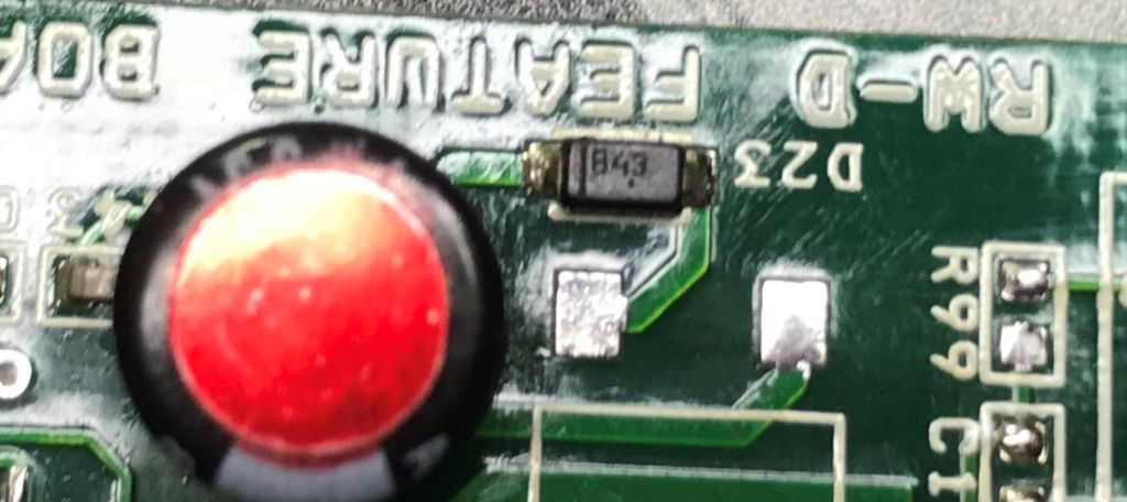
I was not believing my SMD "tweezer tester" which was telling me that D23 was no good.
Once I removed D23 and tested it out of board, it was bad... no clamping at 2.4V at all... I guess that there is always a first time.
Thanks again for your time!
-
Great information in this thread - thank you!
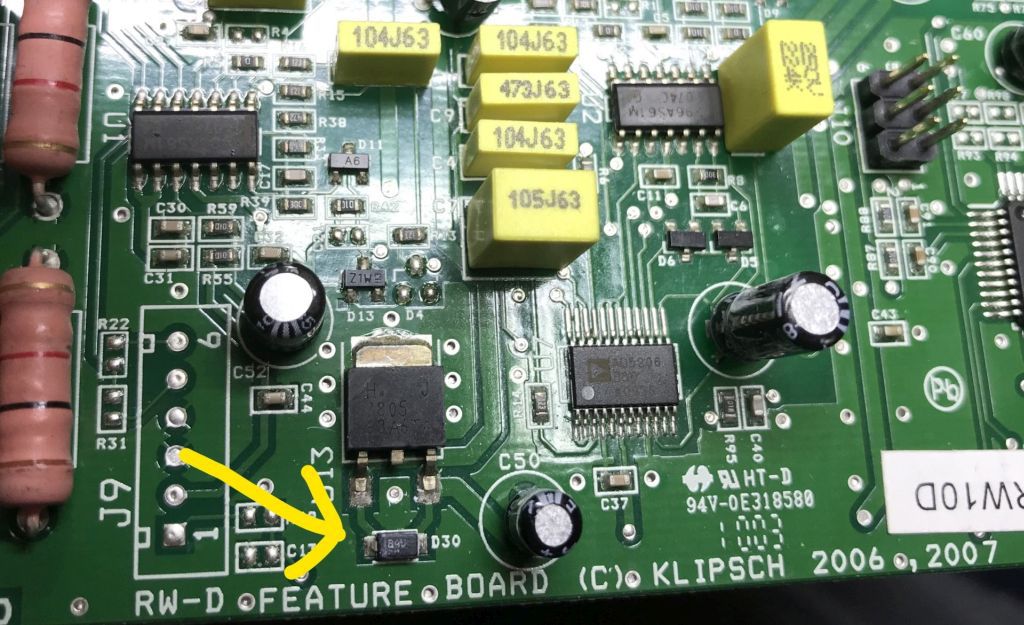
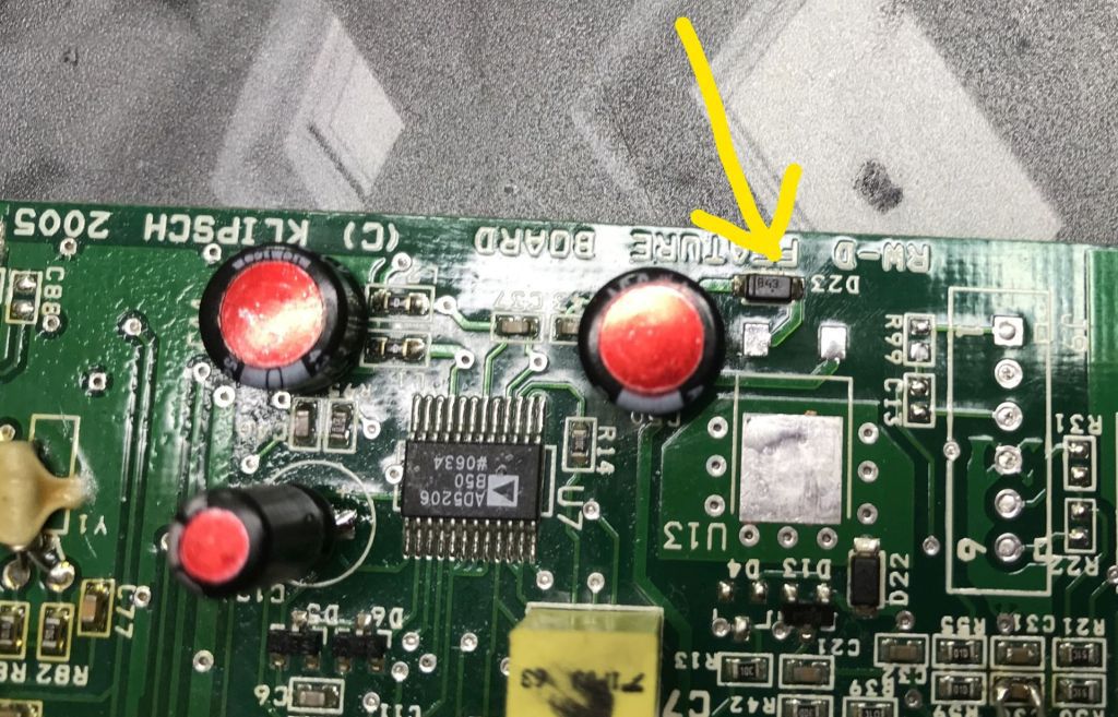
I need some help regarding D23 (2005 pcb) and D30 (2006-207 pcb) in the pre-amp board.
Since I do not have (and cannot find) schematics for the RW10-D/RW12-D amps, I was wondering if you happen to know the actual model for these diodes.
D23 seems to be 843 (or B43) and D30 seems to be B4U.
Looking at SMD codes, I cannot find any diodes that would match those markings.Any suggestions?
Thanks in advance. -
On 4/14/2020 at 12:04 PM, ngen33r said:
I didn't know they made an RPW-10D. I know they made RW-10 and RW-12D subs. When I see that issue on them it typically requires a recap, replacing SMT diodes and the SMT VREG. About 60% of the time the digital volume IC is fried when the VREG goes. Those are not fun to solder in. If it is an RW series, please post in that blog. I want these threads to stay on topic.
My bad - I meant RW-10D.
I was not aware of an RW Series thread, but will look for it.Thanks for the info!
-
Hello ngen33r!
Thank you for the very good and very well documented information provided here so far - very helpful indeed,
I was wondering if you had any luck repairing RPW-10D amps with the typical "LCD does not work but blinks when the amp is turned off" issue.Thanks in advance.

Sub-10 / Sub-12 / RPW-10 Repair Blog
in Technical/Restorations
Posted
Those are not resistors, but "zero ohm links" - a piece of wire (of proper gauge) will do the trick.