ngen33r
-
Posts
166 -
Joined
-
Last visited
Content Type
Forums
Events
Gallery
Everything posted by ngen33r
-
Well it is time for new control boards. Some of these 660045-1 boards are too far gone to repair. Here is my prototype that I am ordering to try out. I rolled my own layout on the board to reduce traces going under parts. More to come when boards arrive.

-
So I did a little research and there are 2 different component values for these boards. If the board has C1 C2 472 capacitors the resistor values are 1.1K 1% BROWN BROWN BLACK BROWN BROWN for R2 R3 R5 R6. If the C1 C2 capacitors are 332 the resistor values are 750R PURPLE GREEN BLACK BLACK BROWN for R2 R3 R5 R6. The RPW-10 that I have on the shelf uses the 1.1K resistors on the PDC. All of the SUB-10 PDC boards that I have use the 1.1K resistors and all of the SUB-12 PDC boards use the 750R. My testing board is made from the guts of a SUB-12 and it powers on no problems with either board, that doesn't mean that it is supposed to be that way.
-
The equipment is an investment and can always be used for different projects. So you didn't waste your money, especially on a Hakko. The BASH boards are usually good, Maybe 1 in 50 I have to replace the IC. That board is a BUCK regulator controller. It takes the output of the transformer and varies the voltage based on the demand of the amp. These amps are Class H which is Class AB with a tracking power supply to gain efficiency. If you have ~5V on the 2 resistors that feed the mosfets the BASH board is good. The squealing is most likely from the main transformer or from the other inductor. The switching frequency is what causes that noise and I have no idea what would cause that without looking at the board. I still think that the PDC has some issues. I have an RPW in my to be fixed box, if I have time this weekend I will pull out the supply and measure the values of the resistors on the PDC.
-
99% of the parts you replaced are never bad. PDC, Q5 Bash Board, caps, NTC and FETS are all I ever replace on these. With so many parts replaced the problem creates new problems, broken traces lifted pads. At this point it is almost better to trash that amp and start fresh with a new broken one, unless you go over the entire amp from a schematic. A SUB-10 power supply is identical to the RPW and is a direct fit on the plate.
-
I am not sure in this application that it matters. The switching frequency is under 1MHz and 99% of the other Bash amps use solid copper in the class H buck supply. I would expect maybe some increase in harmonic distortion or some extra ripple on the filter cap but not catastrophic failure. Either way I went with OEM specs.
-
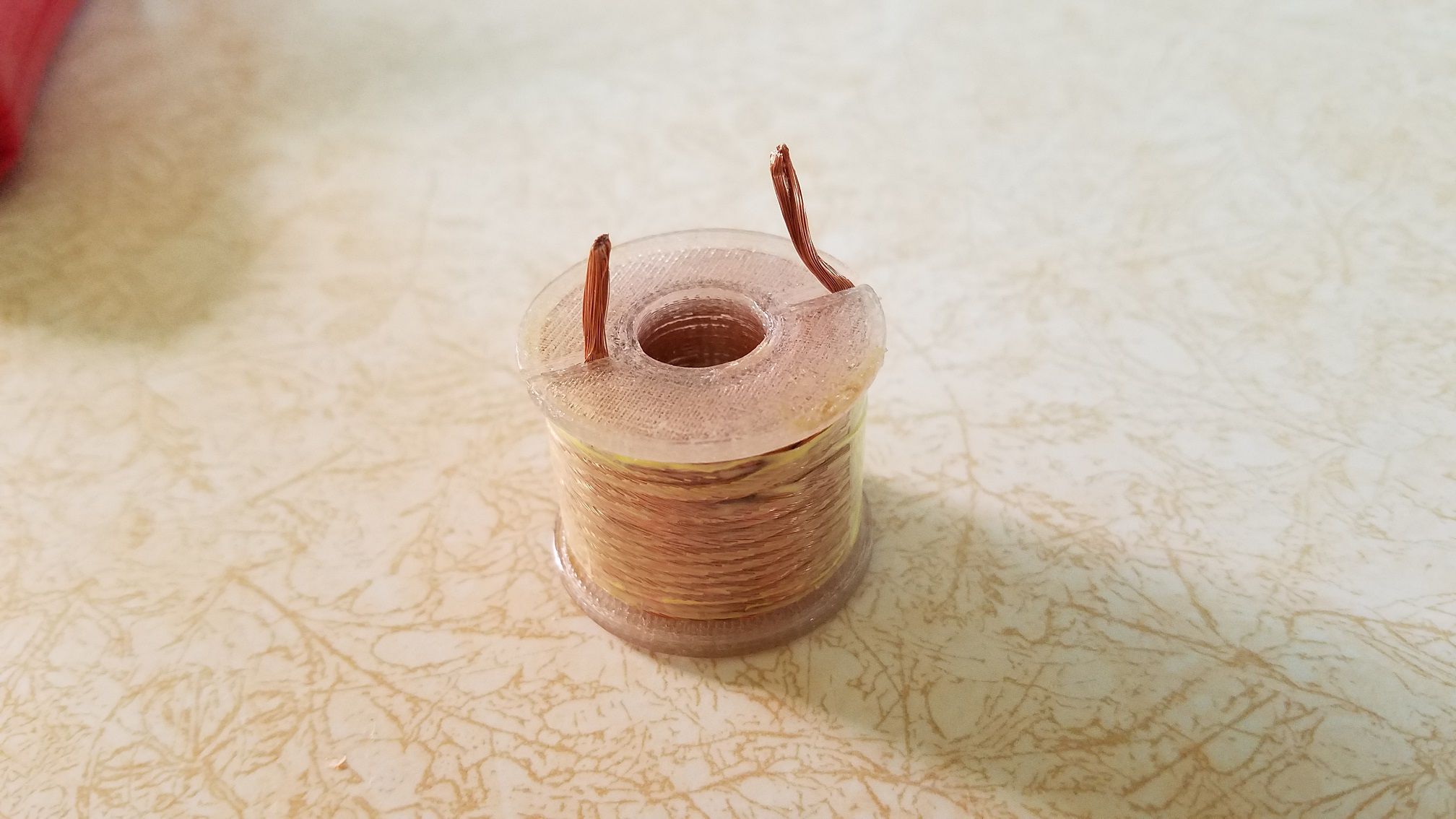
You sound like the competition, I should not be giving out these trade secrets. HAHHAH The wire I used is 80/38 LITZ. Coil ID 16mm Coil Height 22mm 110 Turns It is as close to factory spec as I could get not that it needs to be. 110 turns of 18awg solid would be painful on the thumbs if wound tight.
-
L302. The inductance is 150uH air core. Shorted fets and outputs caused this. The power supply puts out enough power between current limiting shutdown to heat the coil if left plugged in. So if your unit wont come on, don't leave it plugged in. The wire to wind this is stupid expensive.
-
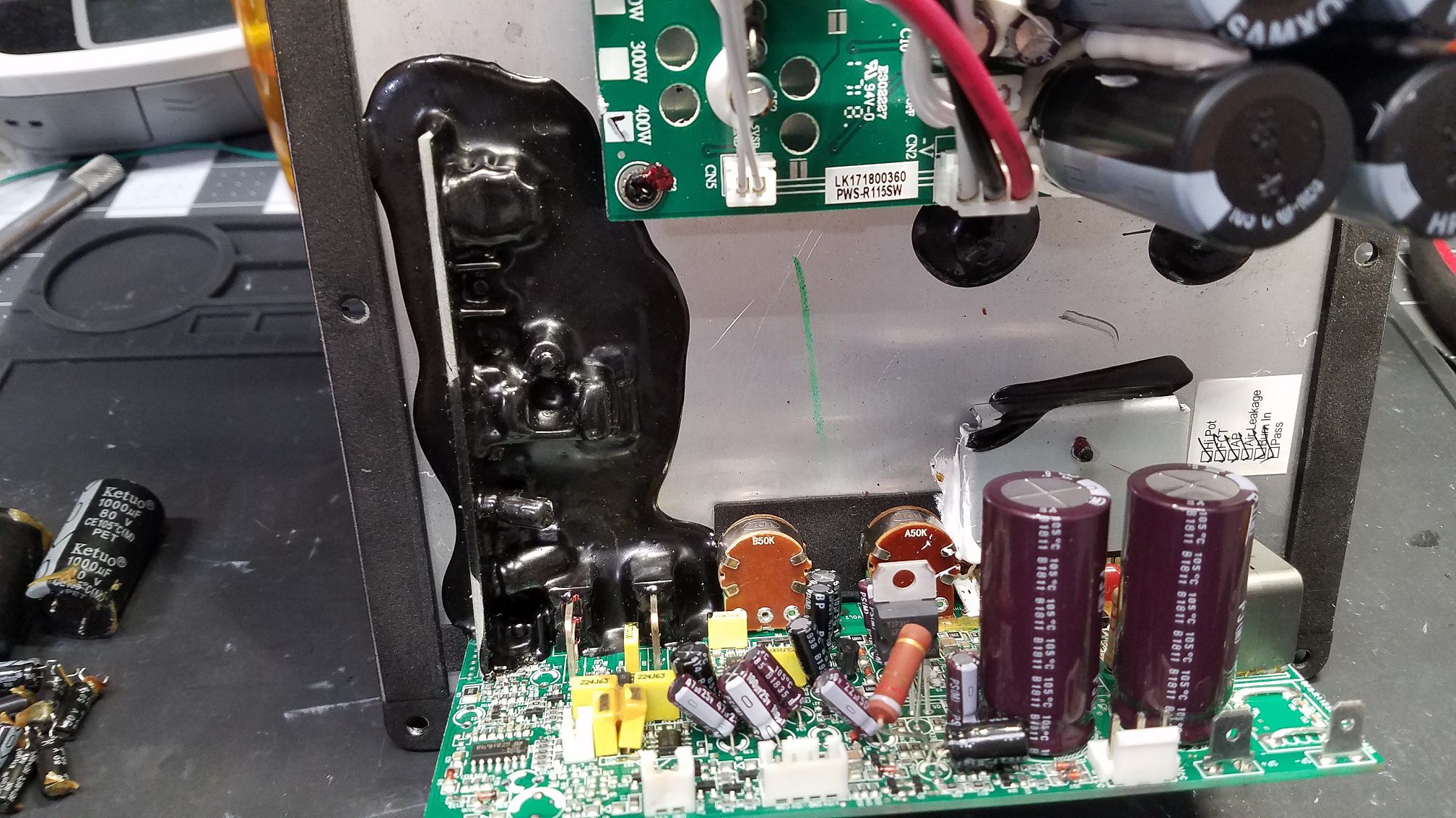
R-110SW / R-112SW / R-115SW Repair Blog
ngen33r replied to ngen33r's topic in Technical/Restorations
R-115SW #LK171800360 I can't seem to achieve liftoff. This one was close but it couldn't seem to make it into low woofer orbit. Replaced everything burnt and blown and a full recap and this one is ready to piss off the neighbors again.
-
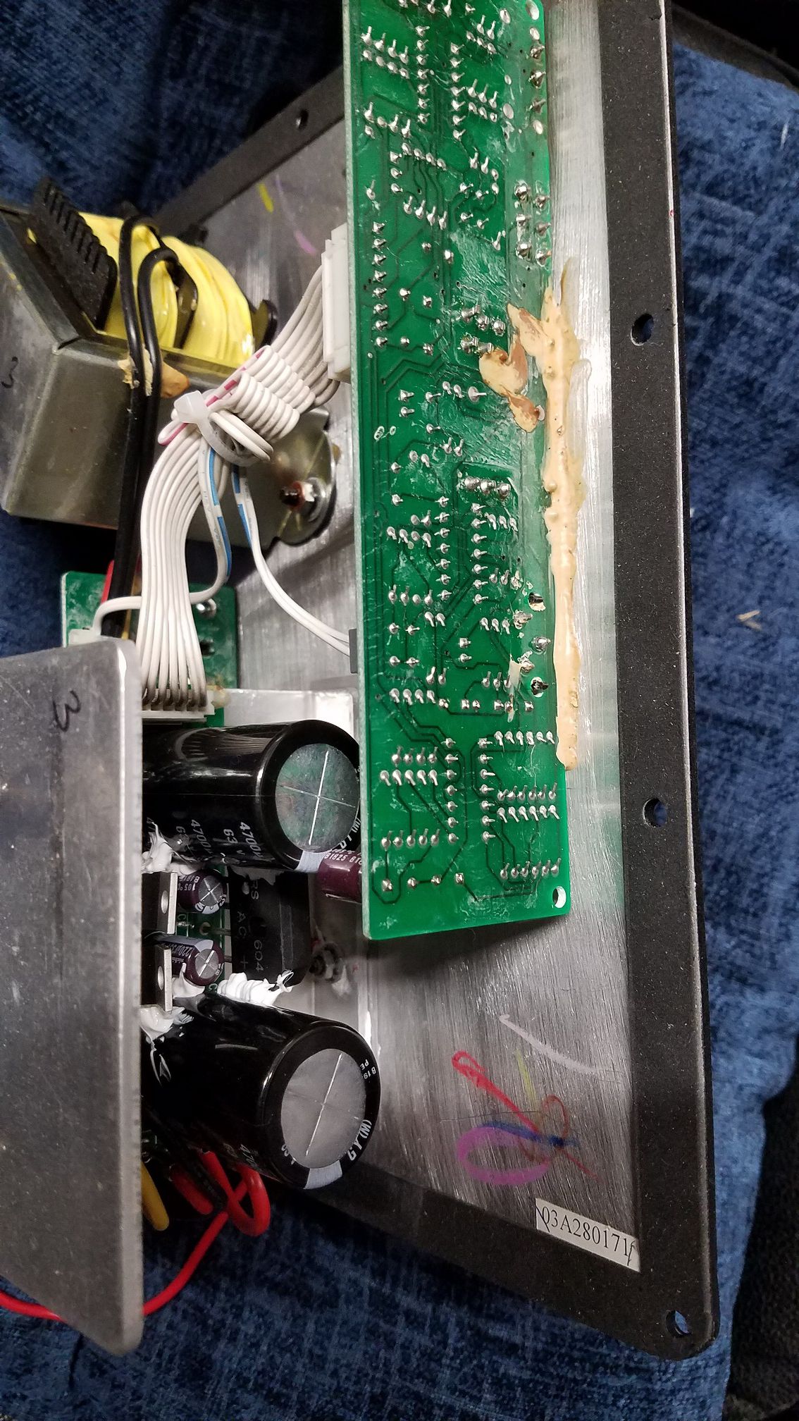
KSW-12 #03A280171 Same with this one, just a recap and it lives again.
-
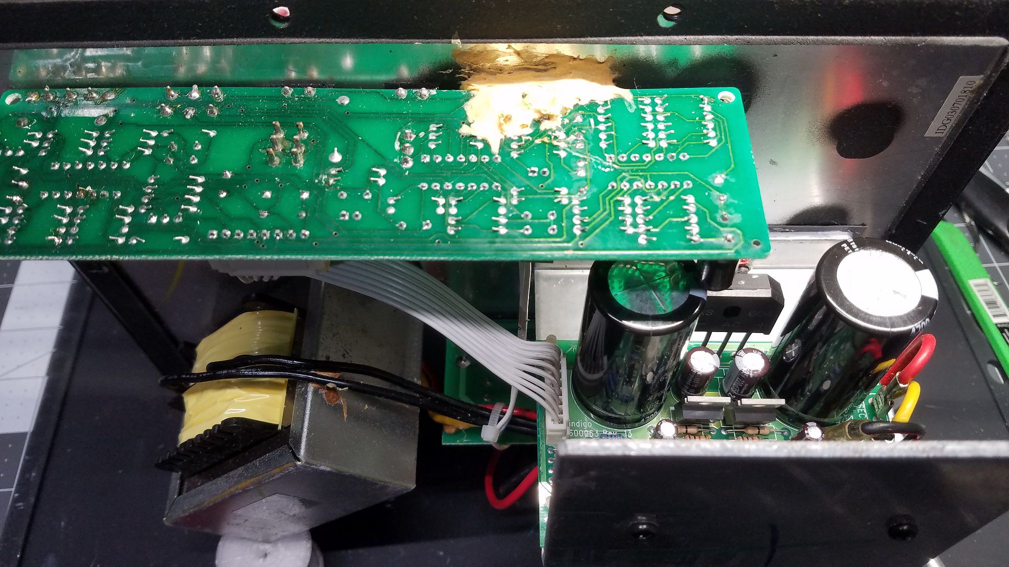
KSW-12 #IDG030701810 This one was rather simple. It had buzzing from leaking caps. No damage to the board so a full recap and it was out the door.
-
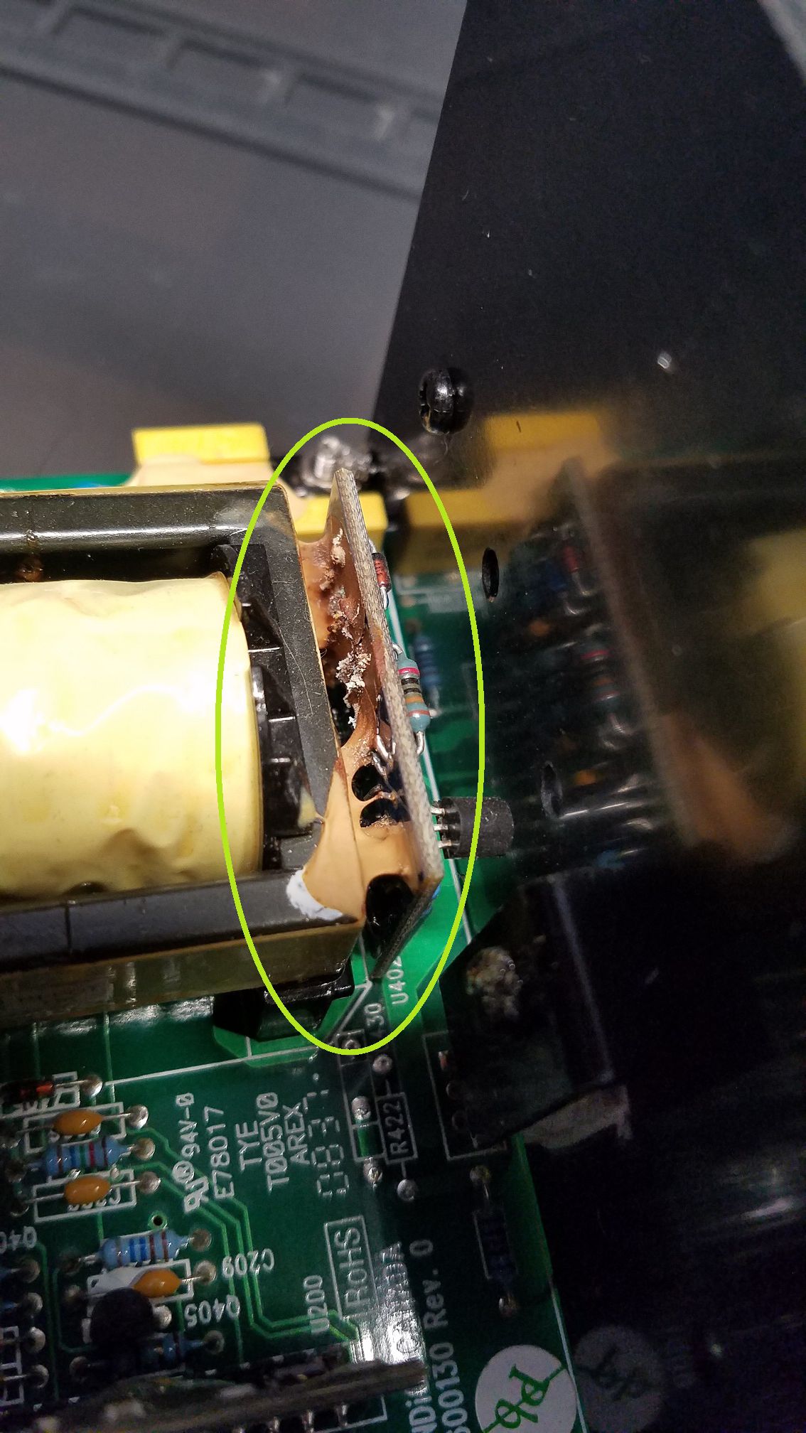
Plate? This is one that separates the men from the boys. This amp came to me a complete mess. It successfully achieved meltdown. The inductor on the secondary power supply overheated and was destroyed. I took some measurements, ordered the special LITZ wire and 3D printed a new bobbin for the coil. I then vacuum potted the coil with thinned polyurethane and let it air dry for a week. I still need to do more repairs on the amp, It has shorted fets and outputs and all sorts of other issues, but here is a teaser for this one. One thing I learned, is definitely to tin the leads before starting the winding and before potting. It was not easy at all to clean them as they wicked up the poly.
-
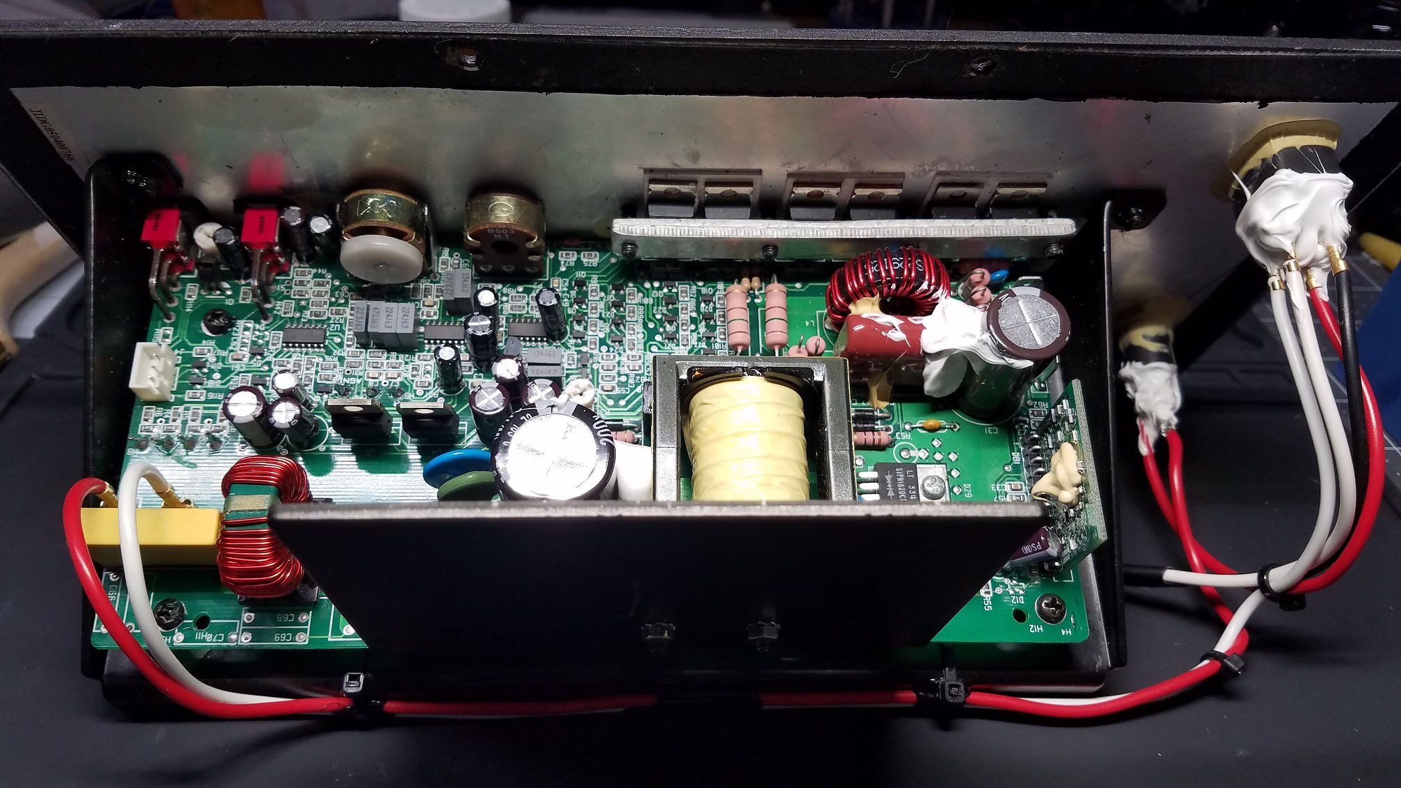
SUB-12 PLATE JIDG050400766 This one was rather interesting. It came to me with all of the power wires cut. I had to do the repairs and rewire the plate. I am not a fan of these all in one style boards. They are a pain to work on. The wires going form the speaker terminals to the plate were also cut. It was almost like someone wanted the copper and trashed the amp. This plate had the glue monster do some damage which is 99% typical for these. PDC rebuild, full recap, new fets and Q5 upgrade.
-
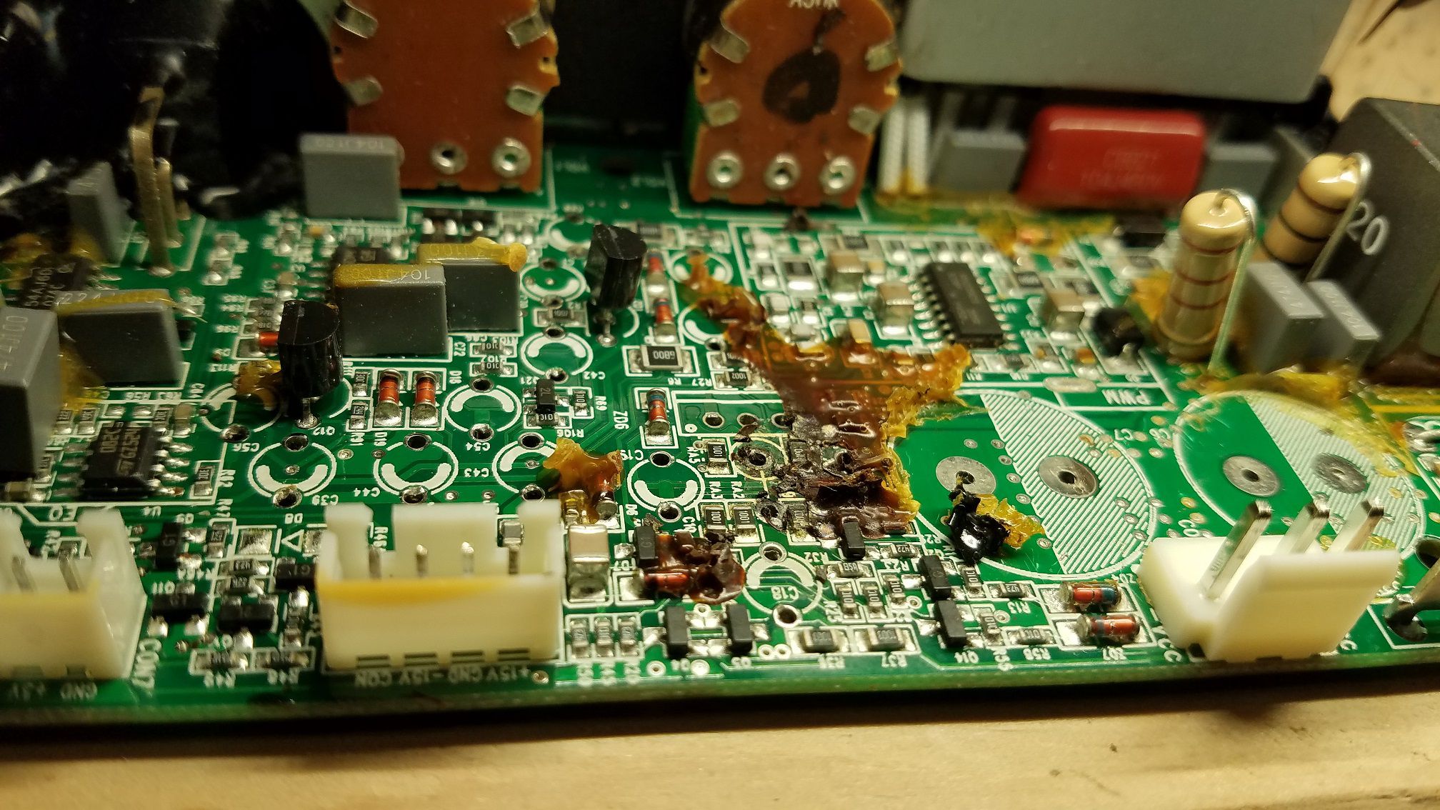
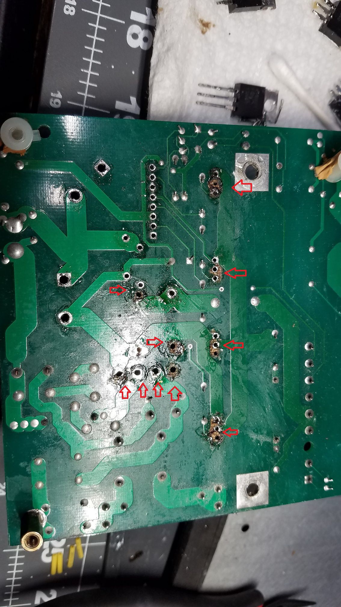
RT?? Here is another that I am working on. It really sucks to see work that is this bad. I had to replace 20 thru holes on this power supply section, because whoever attempted the first repair didn't have the proper tools. $3 a thru hole starts to add up. I am about 40% through this one so more to come. BEFORE AFTER
-
If you don't put the time in and sacrifice a few amps, you wont learn anything. Why quit at 90%? eBay is full of defective amps should you kill this one. The amp still operates in class A/B just the power supply has rail tracking so it runs as a class H. If the bias is not correct the outputs will draw excessive current. Thinking more on it. It sounds like the PDC board is still an issue. I would measure the resistors that you had if you still have them and then double check that board and make sure all the connections are correct. Check the gate drive resistors.
-
The primary switching transistors should not be getting warm at idle if they are on the heatsink. You have some sort of issue with the output mosfets or the bias adjustment. At this point you have to start probing the power and signal path with a scope.
-
User OUNVME is me by the way....before I graduated college hahahah.
-
THE RESISTORS ARE IN PARALLEL ON THE BOARD AND WILL MEASURE THEIR COMBINED PARALLEL VALUE. YOU MUST USE THE VALUES THAT I HAVE LISTED OR THE SUPPLY WILL NOT FUNCTION PROPERLY. The problem is either with the DIAC on the PDC board, Q5 by the BASH board, or the controller on the BASH board. Where did you get the DB6 diac? NTE is the only place I could find the correct one. Things to check (ONLY CHECK THESE IF THE PDC HAS THE COMPONENTS THAT I LISTED INSTALLED) 1 VOLTAGE ACROSS THE 2 REGULATOR HEATSINKS SHOULD BE ~28V If you have this voltage the primary supply is working. If you don't have this the PDC is still not working. 2 VOLTAGE ACROSS BETWEEN THE 2 LARGE RESISTORS BY THE RIBBON CABLE Once side of the resistors is common make sure you measure the correct side. Should be ~5V with no input and volume at 0. If the voltage is around .5V then the bash board circuits are the problem. Pin 5 on the BASH board should be 12V if the surrounding circuits are working. Be careful this board also sees full rail voltage. If you zap yourself, you are doing this at your own risk. Cut Q5 off, don't try to desolder it if it tests bad. You will have to adjust the bias since you replaced the output transistors. This means the 2 pots have to be replaced and you need an oscilloscope. The VREGS by the capacitors should be bent away from the caps and they do get pretty hot. That is normal.
-
Luckily I haven't seen anything that bad yet.
-
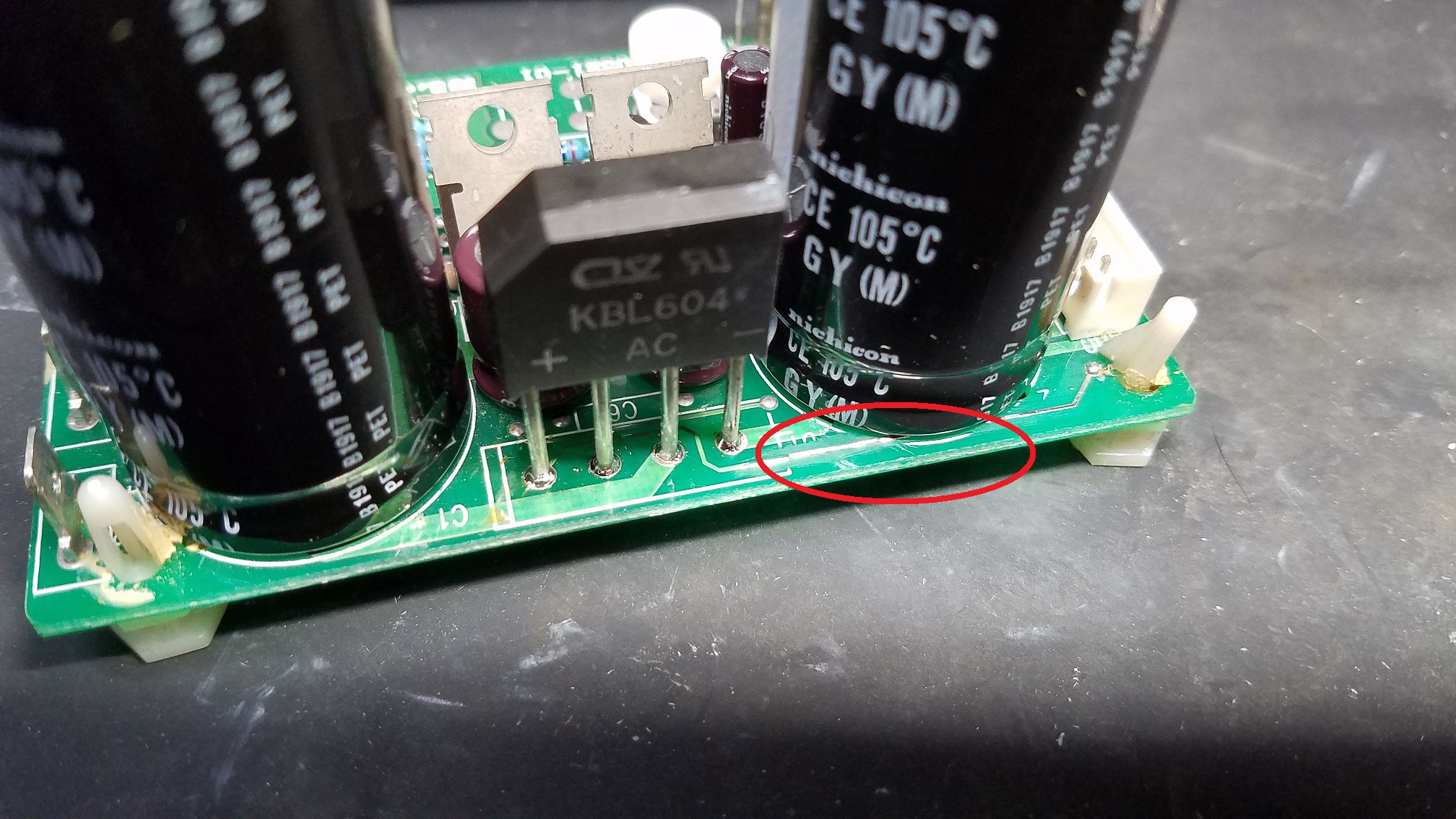
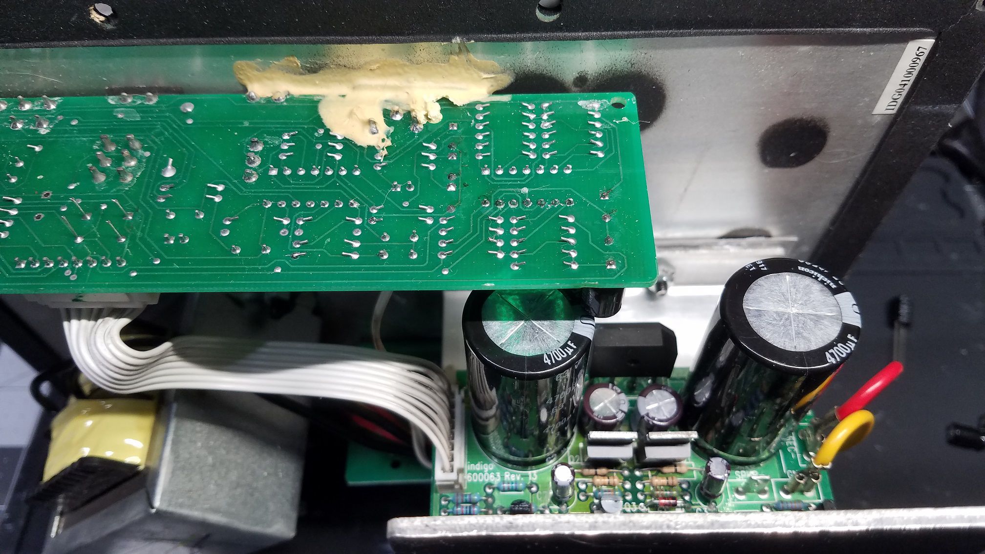
KSW-12 #IDSG041000967 This amp suffered from leaking caps and bad glue. The board needed trace repairs and the amp got a full recap. Z1 and Q3 were shorted and needed to be replaced.
-
Hello All I have been repairing Klipsch subwoofer amps for about 15 years as a hobby. I have decided to start blogging my repairs and eventually do videos of each one. This thread is intended to be a blog and a resource for information. I will try to answer repair questions as best I can. Comments and tips are also welcome, If you do not have the experience or the tools, PLEASE do not attempt any of these repairs. You will only end up damaging the board and it will end up costing more for a tech to repair the damage. If you do not have a high quality vacuum desoldering station (Hakko or Weller) and a current limited mains supply, you should not be working on these amps. These subwoofers do not have any user serviceable parts inside. If you open up the sub or attempt any repair you see in this thread, you are doing so at your own risk!!! Wayne
-
RW-10 - RW-10D / RW-12 - RW-12D REPAIR BLOG
ngen33r replied to ngen33r's topic in Technical/Restorations
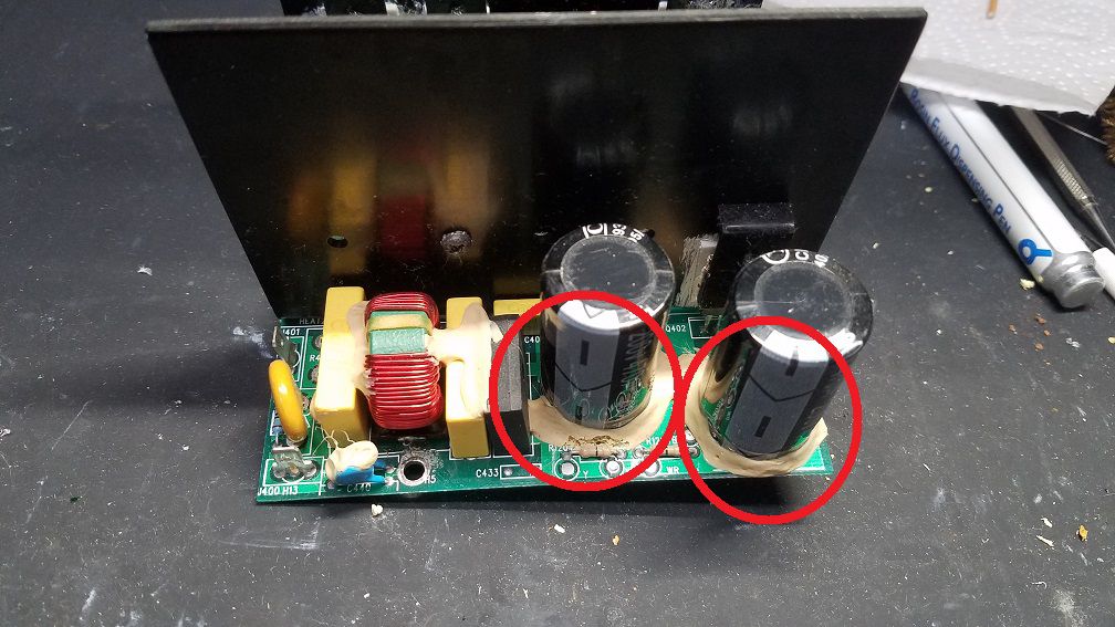
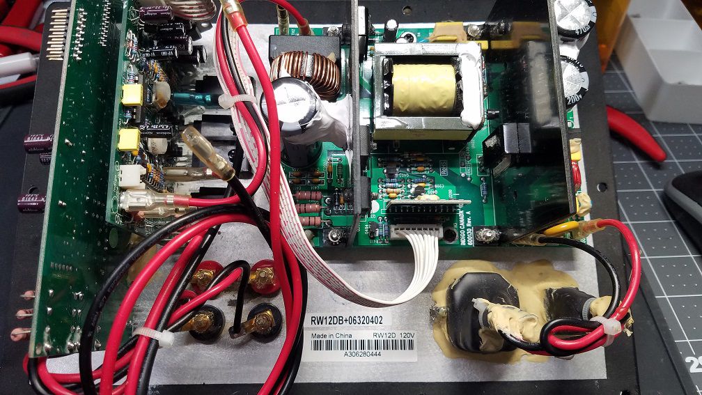
RW12D PLATE SERIAL A306280444 This amp was recently sent in by a forum member. It is a perfect example of why NOT to attempt the repairs if you don't have the proper tools. Nothing against them or their workmanship, but you MUST have the tools for the job or it is going to cost you more. This amp failed from the glue plague. The PDC control board was damaged and the 5V supply was not working. The customer tried replacing the capacitor on the secondary output and tore out the via with the cap. You cannot solder the cap in properly without a plated thru hole. These large snap in thru holes are a pain to replace. I repaired the board and PDC, replaced the FETS, replaced the NTC and did a full recap.
-
This is what I would consider an absolute MUST and in this order. 1 - Have the proper tools to do the job. (Temperature controlled rework station % Vacuum desoldering tool) 2 - Remove any glue that touches the PCB & component legs. 3 - Replace all the Chinese capacitors with the Tier 1 caps of your choice 4 - Replace Q5 if it is an SOT-23 part with a TO-92 part. 2N4401 The glue softens at 155C much over that and traces start delaminating. I use GE silicone II DON'T USE SILICONE I
-
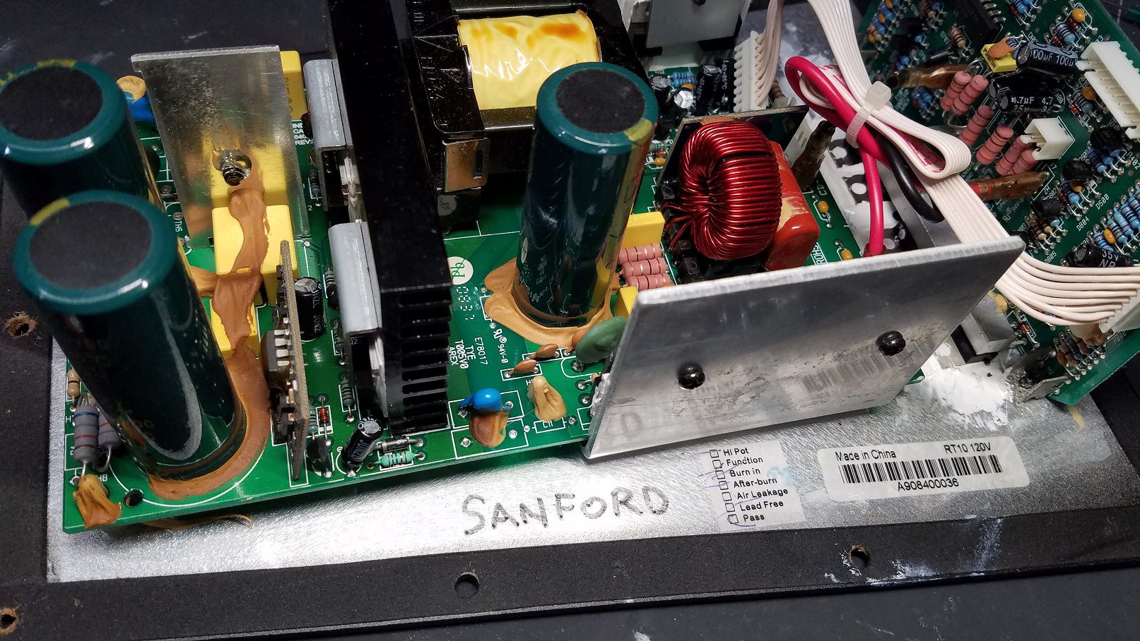
RT10 Plate serial number A908400036 This amp has some nice browning glue causing all sorts of havoc on the power supply. The glue all has to be removed and the whole amp needed to be rebuilt and recapped.
-
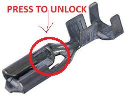
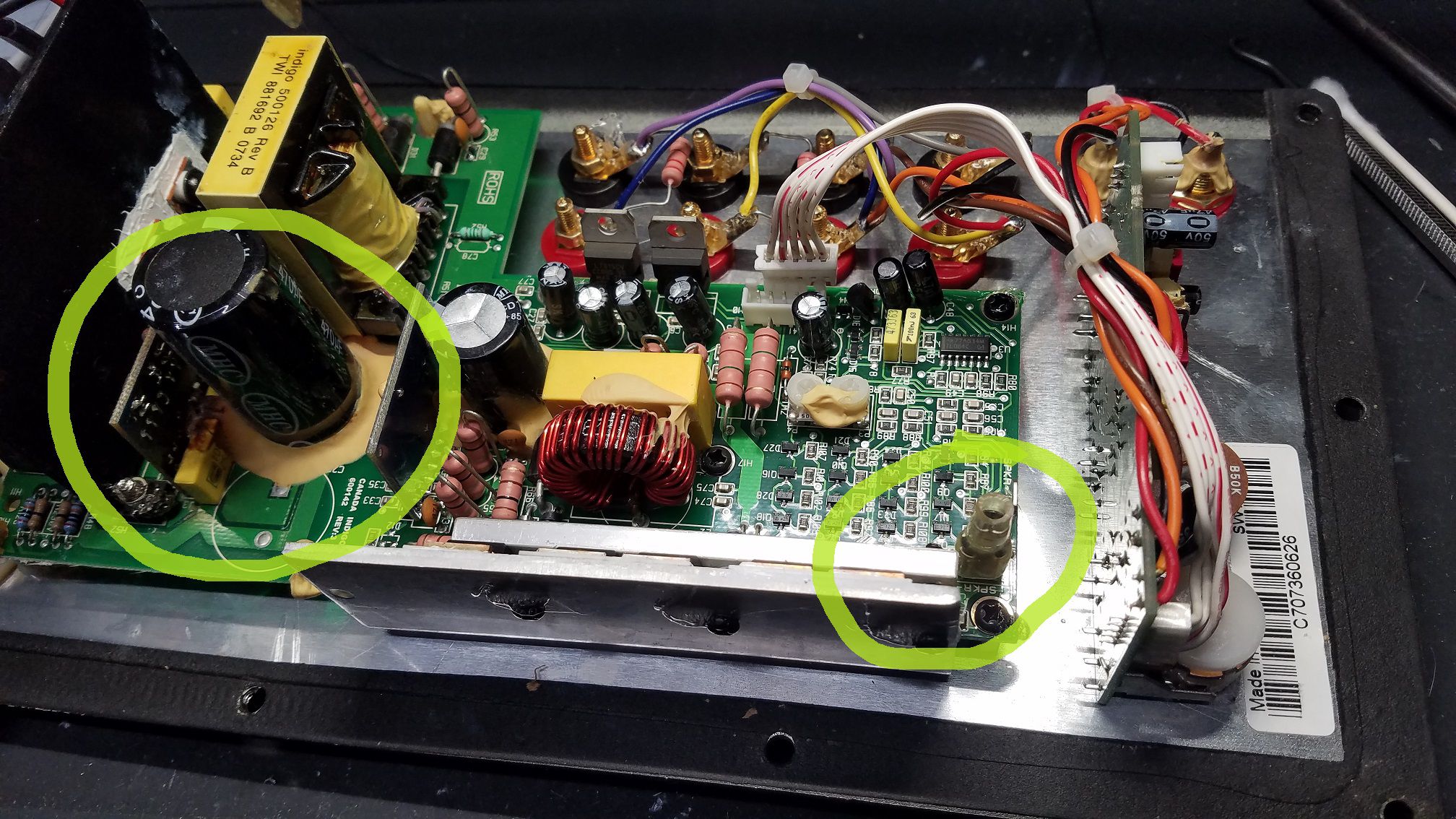
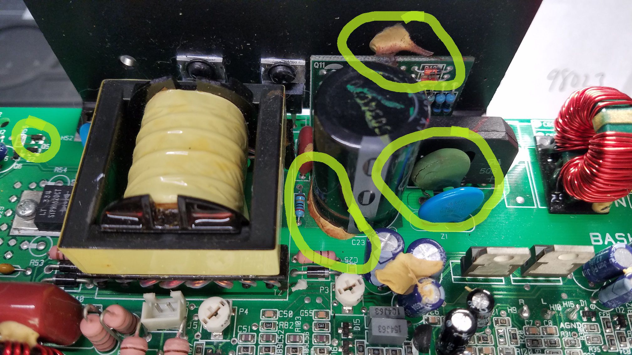
SYNERGY SUB-10 PLATE SERIAL C707360626 SYNERGY SUB-12 PLATE SERIAL ????? This set was sent in for me to go over. The Sub-12 looked like it was in a war. All of the wires were cut, the fuse holder was stuffed with aluminum foil and plenty of parts were deep fried and that is all after the failure from the glue monster. The Sub-10 was not in terrible shape, but it also good and crispy around the glue and PDC board. The owner couldn't figure out how to remove the speaker wire so why not just rip it out of the terminal. These terminals use locking tabs. These are the before pictures
-
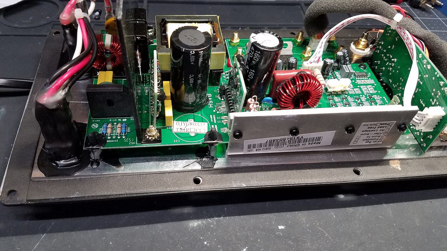
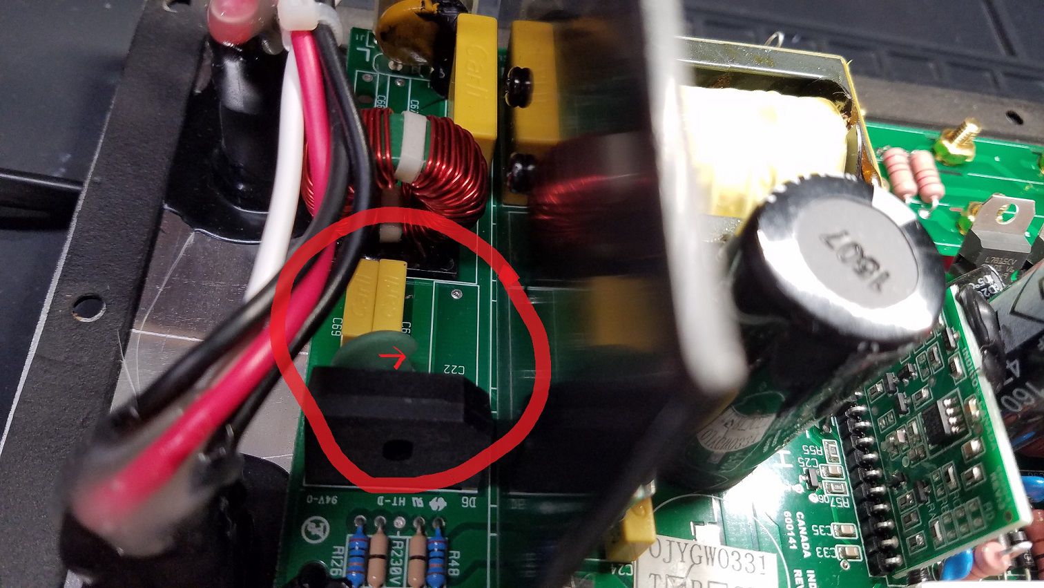
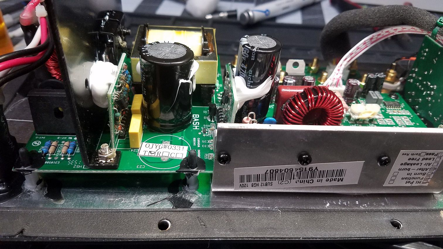
SYNERGY SUB-12 PLATE SERIAL Y9154604807 This is one of the nicest Sub-12 revisions that I have seen. It has all the updates and used a silicone based glue. This one died from a surge or spike. It will get a repair and recap.