


Bman0202
-
Posts
14 -
Joined
-
Last visited
Content Type
Forums
Events
Gallery
Posts posted by Bman0202
-
-
Well once I tested and confirmed everything I carefully applied neutral cure silicone to q5. And let it cure for about 6 hours and tested it and it seems ok. So I shut it down and it sat till today I turned it on and I had nothing. Took the plate off and tested it and I had no 5 volts
As the silicone continued to fully cure it must have hardened and created tension and broke the traces on the board for q5.
So no I have removed q5 and im going to begin fixing the broken traces and resecuring q5 and applying silicone and hoping that this time it doesn't pull more loose.
Ugh!
-
Also I must say.
If I didnt have an oscilloscope, I wouldn't have been able to find this issue. The scope showed me the bad wave being introduced, as well as the voltage drop.
With just a multi meter it would have still be possible but it would have been even more trial and error than what I went through.
The scope is what saved me.
-
On 2/1/2022 at 11:31 AM, ngen33r said:
Looks like the bias pots need adjustment. or the feedback to the opamps from the speaker terminals has a broken trace.
After alot more troubleshooting I narrowed it down to q9 and d17 on the "speaker -" rail. D17 was ultimately dropping too much voltage. Messing with q9.
I measures the 15 volts going in but only 8volts was coming out.
Replaced and now its all good thank goodness. Clean waveform in and out. Adjusted the bias to make sure the wave form looks proper
Thanks tho this forum ive gotten it back up and running
-
1 hour ago, ngen33r said:
Looks like the bias pots need adjustment. or the feedback to the opamps from the speaker terminals has a broken trace.
When I adjust the bias pots im not seeing a change in the noise on the scope really at all.
-
After replacing q7
U3 and u4
The symptoms are still the same.
There is something fishy happening in the amplifier cuircit and I can't find it. This is so frustrating
-
45 minutes ago, Bman0202 said:
Well to my dissatisfaction
When I recieved the new components the new
Q13 and q19 test the same.
So I was wrong.
Now im not sure what to look for.
I cant seem to find where this ugly noise is coming from in the amp.
I might just have to forfeit and purchase one of your repaired units and send you this old one for you to troubleshoot for another potential buyer
Ok well since I have the component's
Im gonna go ahead and change what I have and see what I get.
After replacing q13, q19 and q14, q20 the noise in my previous pictures is still there.
Next ill replace q7
U3 and u4
-
Well to my dissatisfaction
When I recieved the new components the new
Q13 and q19 test the same.
So I was wrong.
Now im not sure what to look for.
I cant seem to find where this ugly noise is coming from in the amp.
I might just have to forfeit and purchase one of your repaired units and send you this old one for you to troubleshoot for another potential buyer
-
On 12/14/2021 at 8:08 PM, ngen33r said:
Hello,
I am doing a little house cleaning and trying to clean up my to-do shelf. Some ofyou have seen my forum posts and videos, but to those that are new, I repair audio equipment as a hobby and have been doing so for over 15 years. I have 2 plates ready to go and I am offering a 1 year warranty on the repair through my LLC Supreme Innovations (www.supinv.com).
I am offering all my current and future repairs to forum members first before listing on other sites.
I am not currently accepting defective plates, but I will pay the shipping on your purchase if you send the bad one back to me. This keeps them out of the landfill and eventually in someoe's living room.
My Repair Channel
https://www.youtube.com/channel/UCOMzk5nU67lbGj1hLzUkmwQ
#1: $115- Sub-10
#2: $115- Sub-10
Shipping NOT included
I accept PayPal CashApp Venmo Zelle
If still available I'll take one.
And ill send you my old one as a core lile you say so maybe you can get it back out there again
-
6 hours ago, GrantCanada said:
Hi this is a great forum. I have an RPW10 and have check the 5V and 28V tests according to Ngen (watched a lot of videos). Tests ok so I think power section is ok. I hear VERY feint music when I plug in a source. Do you think this might be a problem with the pre-amp or main amp section?
Thanks
I was unsuspecting on the amp section
But I found that when I pulled the fets and diode checked them
I found q13, and q19 to be faulty.
They arent shorted. But they were not reading correctly
Ill find out for sure on Tuesday when I get my replacements.
-
This morning I decided to pull the 4 main output Mosfets
Irf914
Q14, and Q20
And
Irf9z14 Q13, and Q19
When diode checking source to drain of irf9z14 p-channel.
Anode is drain and cathode is source. I get 1.065v on one and
1.105v on the other
I then switch on the Mosfet by applying voltage to gate I get continuity from source to drain. I then short the leads.
And check Source to drain in off state and I get 1.065 and 1.105 so they are bad
It should be .500-.600v yes?
Then I check irf914 n-channel.
Anode is source, cathode is drain.
Source to drain in off state its .575v and .580v
I switch on the fet and test and get continuity.
Then short it back to off state and I get the proper diode reading.
So I believe I found my problem.
To be q13 and q19
Q7 irf530 checks correctly at .529
I went ahead and ordered
Q7, q13, q19, q14,q20
And ill replace them all
Then preform the bias test you outlined in your video.
Ill update after I complete those replacements
-
1 hour ago, babadono said:
Something in the amp circuit is breaking into high frequency oscillation.
Could that be the voltage regulators in the secondary supply?
L7815cv
L7915cv
Or the main output section of the amp
Irf530
Irf9z14
Irfz14
-
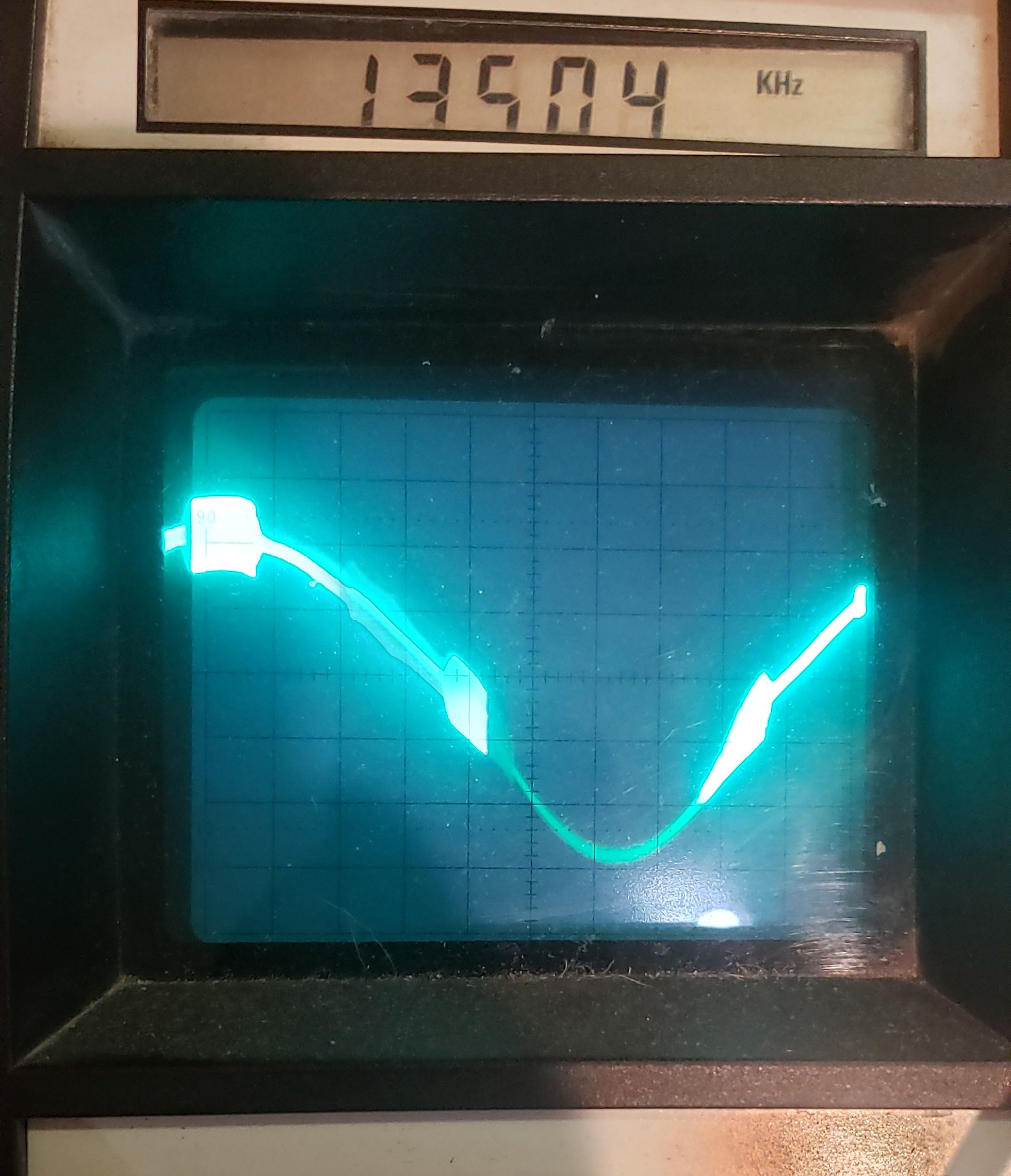
Here's a photo with the volume at 5-10%
Of a 40hz sine wave
-
Hey there this has been a super helpful thread.
I got a sub-10 to repair the original owner said it powers on but its quiet.
I opened it up and found the 470uf 100v cap was bulged
And q5 was toasty
I scraped all the glue
Replaced
Q5
Z2
And all caps
Pdc board was good and fets appeared good. It was not blowing fuses. I get proper voltages
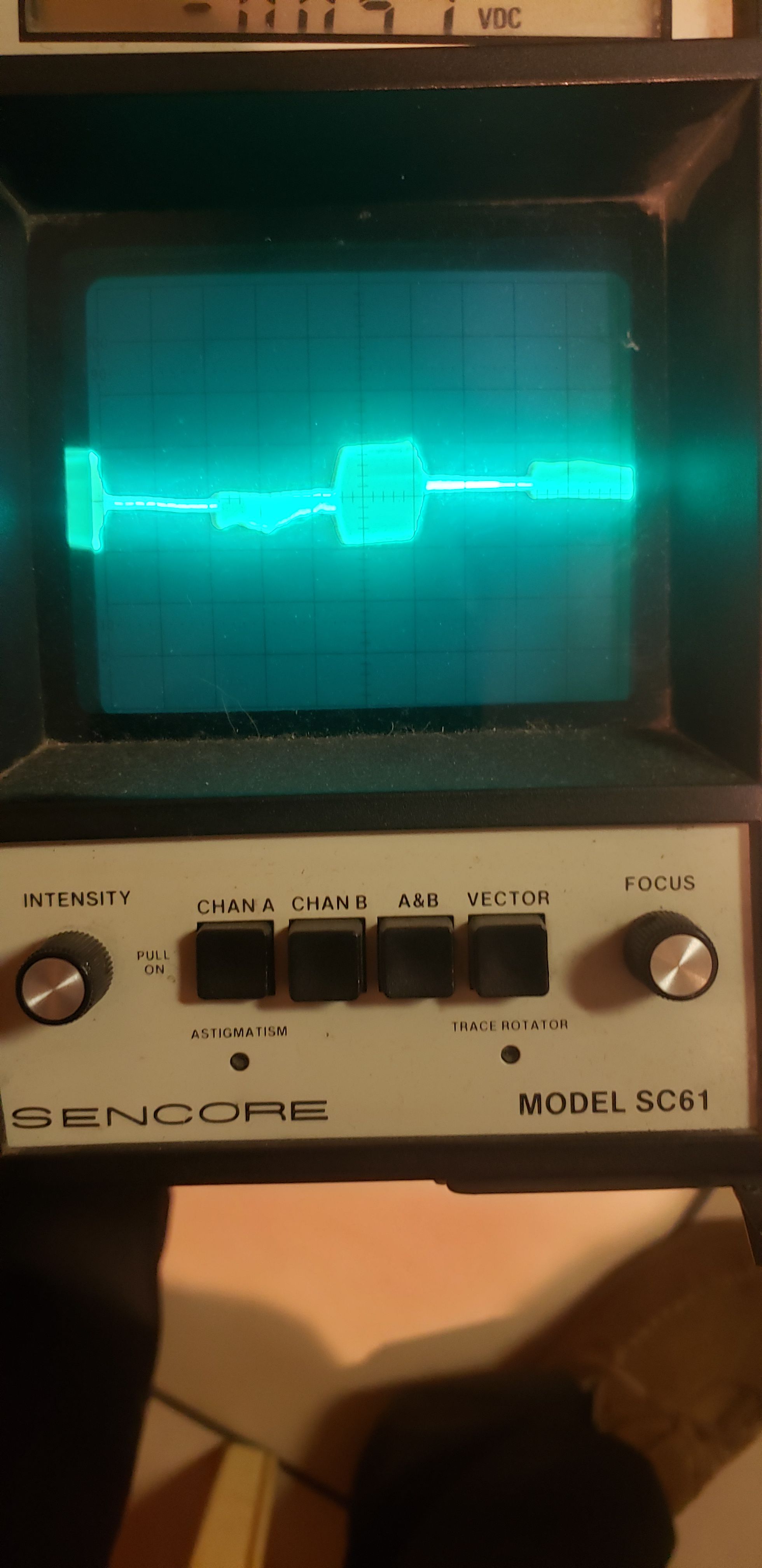
I send a sine wave through and I check the signal path with my scope
And do not get a clean sign wave. I see noise without volume. Once I add volume I see the sine wave and the noise in the sine wave.
It has a like oscilating ripple in the signal
path that appears to be in the 16khz range. (Noise from a component in the board somewhere)
I cannot seem to find where in the circuit its being introduced.
The amp other wise seems to be operating properly
Is it possible that I have some op amp or amplifier fets that aren't bad but aren't good either.
Thanks
Sub-10 / Sub-12 / RPW-10 Repair Blog
in Technical/Restorations
Posted
i used BAS516, however after many attempts (i bought multiples) usually it fails again after installation. usually it will start off good, but then fail and go right back to introducing noise on the one side of the sine wave. and the voltage drops to around 8v through that component. i cannot find what in the circuit is drawing it down. again everything that the MOD for this forum has talked about worked for fixing mine up to this point. i install a new D17 diode and it works for a short while, then i start to hear a static like noise, i throw the oscilloscope on it and i see the same issue as before. its really random, one time it worked for weeks before going back to a failed state. i have yet to figure it out