DrWho
-
Posts
16210 -
Joined
-
Last visited
Content Type
Forums
Events
Gallery
Everything posted by DrWho
-
A K-402-Based Full-Range Multiple-Entry Horn
DrWho replied to Chris A's topic in Technical/Restorations
Can you describe the magnitude of some of these changes? Are we talking 100us, or 3ms? I would be interested to see a plot showing the final EQ + xover of the LF section, the final EQ + xover of the HF section, both overlayed on the combined system response. Like this: You've posted a lot of plots and there seems to be consistently a dip right around the xover range (or peaks surrounding the xover - however you want to think of it). I'm curious if this is because of how you EQ'd the individual driver responses before implementing the xover? And have you read this article? http://www.rane.com/note160.html Do you see the expected changes in phase response when you change the xover types? Going to a butterworth with the same alignment should give you +3dB at your xover frequency (475Hz, right?). Btw, I know it's minutia stuff....just trying to understand how you don't see any changes when changing the filter. I've never seen that behavior before. -
A K-402-Based Full-Range Multiple-Entry Horn
DrWho replied to Chris A's topic in Technical/Restorations
If you can't describe something with an equation, then how do you know you understand the behavior? That's not to imply that having an equation implies understanding (ala Geddes, ha) - but how can you have a complete understanding without any equation? Partial understanding or a gut feel, sure - but a fundamental understanding? Chris made this point earlier in the thread: I totally understand and agree with the overall point....but I think a more complete philosophical approach is to simply improve upon the models where the real world performance doesn't match our expectations. The bench should absolutely be our reality, but that doesn't mean we can't more precisely predict what the bench will show us. And by precise, I don't mean calculating unnecessary precision, but providing metrics by which we can make informed decisions about the inevitable compromises in every system. Empirical approaches are certainly valid, but analytical solutions (verified by the bench) are far more repeatable and allow for way higher levels of precision. I also think much deeper insight is gained when deriving the analytical solution - which is the point I wanted to make at the beginning of this post. One other thing to consider about an empirical approach: what happens if something is built wrong? Do you have enough intuition to determine that the unexpected results were in fact unexpected? Or do you conclude some unknown behavior is responsible and leave performance on the table? To date, I've never seen a system that couldn't be described analytically, and I've never seen it to be impossible to match a proper analytical expectation. I think it too often that people want to believe in magic, or want to believe something is completely unexplainable. Anyways, just some philosophical meanderings since it's been brought up a few times in this thread. -
A K-402-Based Full-Range Multiple-Entry Horn
DrWho replied to Chris A's topic in Technical/Restorations
Ya, I remember Roy mentioning the K402 was a larger version of the K510. If the K403 came first, then why did they skip a number? The K400 became the K401 - then K403 and back to K402? I'm pretty sure I heard Roy telling stories about PWK hearing the Jub LF with K402 combo - and I would have thought that would have happened before the CES showing where they had the wooden K403? My memory is horrible, but I think it'd be interesting to know if PWK preferred the K403 over the K402. I vaguely recall Roy mentioning something about PWK preferring the efficiency benefits of collapsed vertical polars. Efficiency is probably a misnomer (since it should be nearly the same total energy output), but for a given on-axis SPL target it's going to have less distortion. And maybe he actually wanted less off-axis high frequency energy. If the surface you're reflecting off attenuates some frequencies more than others, then technically you want the inverse of that attenuation in the sound coming off the speaker so that the on-axis and off-axis have the same tonal balance. The objects in our rooms that cause reflections certainly do not reflect all frequencies equally... Anyways, not trying to put words in PWK's mouth. I just know the ideal solution is more complicated than only looking at the speaker itself. -
A K-402-Based Full-Range Multiple-Entry Horn
DrWho replied to Chris A's topic in Technical/Restorations
Keep in mind the K403 came after the K402.....PWK wanted to narrow the vertical polars and I think it was more than just simplifying the xover networks. I could be wrong though. I'd love to hear Roy's thoughts on it.- 1210 replies
-
- 2
-

-
- unity horn
- synergy horn
- (and 3 more)
-
A K-402-Based Full-Range Multiple-Entry Horn
DrWho replied to Chris A's topic in Technical/Restorations
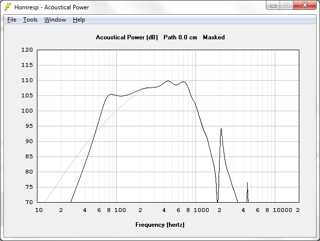
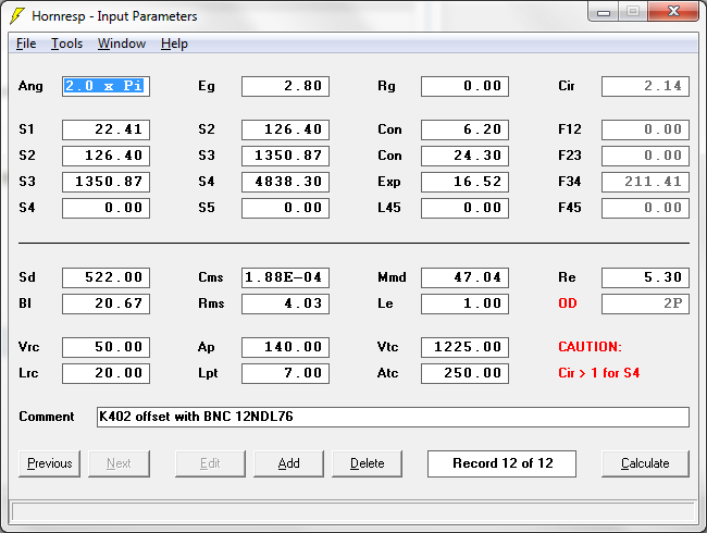
Seriously? That's all it costs? Who's the vendor? I may pick one up next week. If the walls are as flat as you say, then I have some ideas on how to cut one set of "holes" in the horn and experiment with multiple driver / port entry configurations. For some reason I thought they'd be $1500 each. I'm with you Chris - the K402 horn is the major differentiator here. I only want to get down to 80Hz in my application since I have a subwoofer for the bottom two octaves. I have a pair of 12" NDL76 drivers laying around that I'll probably start with. Attached is a simulation with ported versus sealed rear chamber.
-
A K-402-Based Full-Range Multiple-Entry Horn
DrWho replied to Chris A's topic in Technical/Restorations
I totally agree - I don't understand why the tool is offered free of charge without publishing the source code, or at the very least documenting his assumptions and the equations he's using. Not even a reference to the papers he's basing it on. Totally invalid for engineering work, but the results from it are interesting nonetheless if we can trust that he's some kind of sane assumptions. Btw, Hornresp will model tractrix flares....just not with a multiple entry horn. I'm not sure one could combine a conical and tractrix flare using lumped element modelling anyway - I think that would necessitate a boundary solver of some kind.- 1210 replies
-
- 1
-
-
- unity horn
- synergy horn
- (and 3 more)
-
A K-402-Based Full-Range Multiple-Entry Horn
DrWho replied to Chris A's topic in Technical/Restorations
It's pretty good out to 80 degrees (included angle), or 40 degrees off-angle. I remember Roy mentioning that anything above ~8kHz is really controlled by the driver itself. My own calculations have shown that to be a true statement--it's related to the phase plug geometry. I'm sure that the last few notes above 10 kHz that are audible will be different with a TAD driving the horn. The part that I find interesting is that the notch only exists in one plane - not the other. Is the driver not axisymmetric? -
A K-402-Based Full-Range Multiple-Entry Horn
DrWho replied to Chris A's topic in Technical/Restorations
While I don't have the closed formula for a finite conical horn resistive impedance, loaded at the throat and then loaded a some intermediate position between the throat and the mouth on the horn's wall, I can say the following: 1) It is the resistive part of the impedance that counts for efficiency loading, not the reactive part, so that portion of the impedance equation for a conical horn for reactance must be subtracted out. 2) the formula for a finite conical horn throat impedance can be found on the bottom of the 126th page of Olson's Acoustical Engineering The plot of throat resistance and reactance for a finite conical horn is shown on the 128 page of that same book. I don't have the formula for the off-axis port impedance vs. frequency for a finite conical horn, but my guess is that a little messaging of the two referenced resources above will yield at least an approximation for the impedance at any point along the horn walls, which is what Danley's plot is basically showing: relative port impedance cut-off levels for off-axis ports along the horn. Chris I don't know what equations Hornresp is using, but it does provide acoustic impedance plots. Attached is a PDF comparing a few different horns: Normal = Crites driver firing into throat of 40Hz Fc Conical horn with a length of 40cm. Offset1 = Same driver horn, but 10cm down the horn. Offset2 = Same driver horn, but 5cm down the horn. Direct Radiator = Acoustic impedance of just the driver itself. Acoustic_Impedance_Comparisons.pdf -
A K-402-Based Full-Range Multiple-Entry Horn
DrWho replied to Chris A's topic in Technical/Restorations
For that to be true, wouldn't the acoustic impedance of the driver also need to be entirely resistive? Doesn't the driver impedance change with frequency, and does that not therefor require a reactive portion to its impedance? When I have some time this weekend I can go find the actual equation. I seem to recall that being why we talk about everything in terms of ka. Also, I think we're looking for maximal power transfer here - not necessarily efficiency: https://en.wikipedia.org/wiki/Maximum_power_transfer_theorem ...but thinking about this some more, the Maximum Power Transfer Theorem assumes infinite current capability in the voltage source. In the case of an audio amplifier, we get more power transfer with a higher load impedance than our source impedance because our output stages have limited current capability (we can achieve the same current at multiple voltages). In much the same way, we have limited excursion capability in our drivers. Shouldn't we be addressing the acoustic output as a function of driver excursion instead of input power? Btw, there's a lot of thought behind these questions - it's actually a pretty loaded topic when you start thinking through the implications. The next piece in my measurement rig will be a laser to measure cone excursion, so I can start correlating designs to the cone excursion requirements for a given target SPL. My thought is that we don't necessarily want to maximize efficiency of the system, but rather want to minimize excursion. The part that applies here is whether moving the driver down the horn actually reduces the excursion requirements for a given SPL versus having the driver at the throat (the Horn A and Horn B examples I gave). In the horn I build (after my tenants get caught up on rent), I'm thinking about trying to move the port closer to the throat so I can have a higher xover frequency. I also don't need as much low frequency extension since I have some crazy potent subwoofage already (othorn). However, I'm intrigued by the idea that moving the driver port closer to the throat will actually increase cone excursion for the same SPL. I don't think that's true, but if what you're implying from Danley's comments in true, then that would certainly be the case. In other words, is there an ideal location in the horn for a given low frequency corner? -
A K-402-Based Full-Range Multiple-Entry Horn
DrWho replied to Chris A's topic in Technical/Restorations
How anechoic would you say these measurements are Chris? It's frigid cold up here in Chicago so I'm having a hard time picturing you taking things outdoors, haha. Those polars are indeed impressive. The differences in the ~15kHz region are kinda interesting. -
A K-402-Based Full-Range Multiple-Entry Horn
DrWho replied to Chris A's topic in Technical/Restorations
Think all you want, but a proper understanding of something includes measurements and/or equations to describe that behavior. Are you able to quantify how much of a load the front chamber and port entry is providing at low frequencies? This is what engineers do - we understand the world through equations and measurements, and communicate it to each other through equations and measurements. The math/science here is the language of understanding, which is very different from armchair engineering. I can't help but notice a massive amount of defensiveness from you, which doesn't improve anyone's understanding. It just makes everything personal and combative. Nothing about the equations and trying to understand the design and its tradeoffs should affect someone else's subjective impressions. It certainly never affects my own subjective impressions - which is important because an unbiased correlation between the subjective and objective is incredibly valuable. It's also my opinion that to spend so much time analyzing a design is really the best compliment an engineer can give. Chris is/was an engineer so I hope he feels much the same way. All that to say - my only intent here is to further understand the mechanisms at play. Even after I get my own units to play with myself, I am still going to ask myself the same questions and do the same exploration. What we're doing here is sharing in that quest. It's boring running off and doing things on your own, and the reason I've stopped sharing my explorations here is because they have nothing to do with Klipsch and nobody here can relate. Here we have a common love for the K402. So again I ask - how much loading are we getting from the front chamber area and its port entry into the horn? "Enough" is such a boring answer -
A K-402-Based Full-Range Multiple-Entry Horn
DrWho replied to Chris A's topic in Technical/Restorations
Different subject, but here's an interesting thesis on beamwidth calculation techniques: https://digital.library.adelaide.edu.au/dspace/bitstream/2440/41350/8/02chapters1-4.pdf I came across it looking for an equation for a truncated horn. -
A K-402-Based Full-Range Multiple-Entry Horn
DrWho replied to Chris A's topic in Technical/Restorations
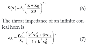
Ya, I'm familiar with that plot, but it's not the same as showing throat impedance. That plot correlates the slope of the instantaneous area expansion to the slope of an ideal expansion for a given Fc. It's a subtle difference, but I'm not convinced the expansion rate itself is what dominates the loading presented to the driver. Let's take two horns both using the same driver: Horn A has an area expansion slope of X starting at the throat. Horn B has an area expansion slope of X starting at some distance away from the throat. They both have the same final mouth area (which means Horn A is longer than Horn . At the point where the driver enters the horn, the actual cross-sectional area will be smaller on Horn A than on Horn B. Doesn't this mean Horn A has a larger compression ratio than Horn B? And by extension, wouldn't that mean Horn A will have a higher throat impedance, and overall be a more efficient horn? Am I missing something? The attached equation is for the throat impedance of an infinite conical horn. St is in the denominator, so a larger St has less impedance. St would be the location where the driver enters the horn, right? This is also assuming an infinite horn - I've not seen any calculations for a truncated horn, but I'm sure someone has determined those equations at some point.
-
A K-402-Based Full-Range Multiple-Entry Horn
DrWho replied to Chris A's topic in Technical/Restorations
Does mounting the driver further down the horn actually increase acoustic loading at low frequencies, or does it just have less loading at all frequencies which makes the rolloff seem less? In other words, put 1Vrms at a low frequency into the driver mounted at the throat of the horn. Does it produce more SPL (in the far-field) than the same driver mounted further down the horn? I would expect the SPL to drop slightly. Or maybe the issue is a reactive component in the horn? Kolbrek shows this in Figure 2 on Page 3: https://www.grc.com/acoustics/an-introduction-to-horn-theory.pdf Is offsetting the driver actually shifting the reactive portion of the horn in such a way as to actually improve the coupling? The part I struggle with is that if I put the driver all the way at the mouth of the horn, then there is no acoustical loading provided by the horn. Perhaps there is an ideal offset for a given low frequency target? I wonder if this isn't what Roy is alluding to in his comments about tradeoffs: a slight decrease in efficiency. Although that should be balanced against the idea that we can have more drivers summing coherently with such an approach...and amplifier power is effectively free from a sound quality perspective. I'd even go so far as to argue that increasing the amplifier power requirements is a sonic benefit (in part reference to PWK's funny article on the LSH speaker: https://community.klipsch.com/dope/Dope_740400_v14n1.pdf) -
A K-402-Based Full-Range Multiple-Entry Horn
DrWho replied to Chris A's topic in Technical/Restorations
Interesting - how would you describe the difference? Or what is it about the 305 that you don't like? Do you think it could be a xover/acoustical summing issue with the other units in your system? Or maybe that you just listen too close to the entire system? (not enough space for the wavefronts to become coherent). Off-axis polars in the xover range? Distortion? -
A K-402-Based Full-Range Multiple-Entry Horn
DrWho replied to Chris A's topic in Technical/Restorations
Btw, did you spend any time listening to the original 8" driver on the K402 horn? I'm curious about your impressions as it relates to the other two systems. You did start with a KPT-305 right? I'm not surprised that better lower midrange performance would be perceived here....from day one I've complained about some unidentified artifact in the folded bassbins. I imagine that would be completely gone here? I feel like I'm the only one that notices that midrange thing on the Jub LF, but maybe you're hearing it now that you have something on par with so many other aspects of the design? Or am I still crazy? haha. Btw, thanks for letting us live vicariously through you. I'm seriously interested in picking up a few horns to experiment with on my end. I have a few experiments I'd like to run on the woofer ports too. Isn't part of the port design that a circular'ish wavefront doesn't fill into the corners of the horn? Isn't that why they're always in corners instead of the middle of the horn wall? -
A K-402-Based Full-Range Multiple-Entry Horn
DrWho replied to Chris A's topic in Technical/Restorations
"Heck of a lot" - care to quantify that in numbers so we can all relate? I'm seeing 1 to 2 dB of difference between the two after accounting for the extra 5dB of output on a system that is already +/-15dB over the passband. The systems already require EQ. In my world, 2dB is "tiny" relative to the 30dB of correction that is already required by the original design. Ironically, that 2dB of difference is sometimes in the better direction. I'd say more identical that not. Keep in mind you're the one claiming that Ricci and an entire website full of data "loses all credibility" because he compared a horn design with different drivers in it. I'm not going to speak any further on the topic because it totally doesn't matter. If you want to use a different driver, then nobody is stopping you. Pictures do speak a thousand words though.
-
A K-402-Based Full-Range Multiple-Entry Horn
DrWho replied to Chris A's topic in Technical/Restorations
The way that it is constructed--I agree with you, but for its effective properties related to flare rate expansion vs. off-axis port location (the low-pass acoustic filter), it behaves just like the horns that Danley uses. So for the simplicity of calling it something other than "the straight-sided walls of the modified tractrix horn", I'll just refer to that area as a "conical", even though it doesn't expand on an x^2 profile. Chris to make it even more simple, just call it a megaphone....... Works for me! haha -
A K-402-Based Full-Range Multiple-Entry Horn
DrWho replied to Chris A's topic in Technical/Restorations
Have you seen this article? http://www.data-bass.com/data?page=content&id=82 After seeing the drivers they used in the DTS-10 tests Data-Bass lost all credibility in their testing methods. You cannot just throw any driver in any style cabinet and expect it to work properly. Two thumbs down. :emotion-45: Wow. I agree that you can't just swap drivers all random like, but your insinuation here is just flat out ignorant. Ricci has measurements of the DTS-10 with stock drivers and the LMSR drivers. You can even overlay them on his website. The LMSR has 5dB more output all around and better LF extension. If anything, credibility should go up because Ricci knew that driver would perform better before even sticking it into the cabinet. -
A K-402-Based Full-Range Multiple-Entry Horn
DrWho replied to Chris A's topic in Technical/Restorations
Chris, have you measured the response of the TAD driver on your multiple entry horn versus the stock K402? Are you seeing any tradeoffs to the compression driver performance? -
A K-402-Based Full-Range Multiple-Entry Horn
DrWho replied to Chris A's topic in Technical/Restorations
Have you seen this article? http://www.data-bass.com/data?page=content&id=82 -
A K-402-Based Full-Range Multiple-Entry Horn
DrWho replied to Chris A's topic in Technical/Restorations
A couple thoughts here: 1) It's possible to model a vented rear chamber in hornresp to see how the front wave and rear wave couple. The loading in front of the driver definitely affects the diaphragm excursion, which in turn affects how energized the port gets. I've had decent correlation between the model and real world when playing with this in the past, but that might be a bit harder here. 2) Keeping group delay under 1.5 cycles (or better yet 1 cycle) is one of my design targets - but it needs to be looked at after the total system EQ. Even with the model you're showing, a peak like that is going to need some EQ, which in turn will reduce the phase rotation. 3) When comparing phase response against a sealed system, it's important to have things EQ'd to the same final shape within the passband. 4) In my experience the Q of the port for a target bandwidth is mostly dominated by the driver. The rear volume mostly affects how much gain you get at the port frequency, which I suppose is technically affecting the Q too, but that's secondary to the driver selection. If instead you go to a passive radiator, then you can modify the Q separately from the active driver. I'm not recommending going to a passive or to change the active driver, just trying to share some info about modifying the Q. Actually, now that I'm thinking about it....I remember reading a long time ago that you can have a massively flared port and that can modify the Q. I've also read about having multiple different sized ports in a design too. 5) I actually did a full on port design the other day when working through your numbers, but didn't publish it because I wasn't sure about the accuracy of the model. I was able to find a port alignment where the frequency response gain matched the diaphragm excursion - which means if it were EQ'd to be the same response as the sealed alignment, then the cone excursion would be roughly one fourth that of the sealed alignment. Then where the system is rolling off, EQ could be applied to increase the low frequency extension while also keeping the cone excursion less than 1/4 the sealed alignment. Then at way lower frequencies a high pass filter would be required to keep the cone excursion down to the same level as the sealed enclosure. Basically you end up with the same final frequency response with a quarter of the cone excursion. Yes, there would be some extra group delay in the final alignment, but it wouldn't be huge. -
A K-402-Based Full-Range Multiple-Entry Horn
DrWho replied to Chris A's topic in Technical/Restorations
Since you bring up the intended audience....the most common complaint I've heard is SPL handling - especially at high frequencies. Even when not pushing the levels, several complain that the highs are attenuated a lot more than other cabinet designs when listening in the far-field. -
A K-402-Based Full-Range Multiple-Entry Horn
DrWho replied to Chris A's topic in Technical/Restorations
This is probably totally off topic, but I think it is possible to design a bass reflex that doesn't have that flabbiness sound. Or maybe we have different thresholds/definitions for flabbiness. The biggest variable from an IMD perspective is an appropriate high-pass filter to address the woofer unloading below the tune frequency. And if you have active xovers in the mix, then you should implement a peaking high pass filter to take advantage of more free output - which generally means you can get away with a lower tune frequency (which also makes it sound more like a sealed cabinet over a wider bandwidth). Then your port needs to be properly sized (most are way undersized), and it should be flared. The last remaining variable is the pipe resonance of the port (which is lower Q with the flare), which can be address with careful placement inside the speaker enclosure (providing 1/4 wavelength cancellations inside the box). Then you need appropriate absorption inside the cabinet to keep high frequency energy from getting out through the port (along with attenuating all them internal standing waves). You just won't find that recipe with the Klipsch pro cabinets.... The Palladium lineup is probably the closest Klipsch gets to that. Many other pro cabinets will intentionally undersize their ports so that at high SPLs, the port compresses a lot helps prevent the woofer from unloading too much (it starts to approximate a sealed enclosure). Not a good sound, but at least it protects the voice coils from slamming against the pole piece. Before this happens, you often get a frequency response that changes with output level - and that change looks like a narrow Q boost, which will tend towards one note sounding louder than others. A lower Q design (low group delay) with a full sized port doesn't tend to exhibit these effects. I only bring it up because I've done a lot of side-by-side vented versus sealed comparisons, and when the two systems have the same frequency response, the vented system has way lower IMD....even when measured in room. I'm not saying you have to port your cabinet here, but 16dB of boost to get 60Hz to match the output at 300Hz is a lot of EQ... Btw, I agree that you can double up on drivers and get even better performance all around....but like Roy talks about with horns, you can always add ports to that total system. -
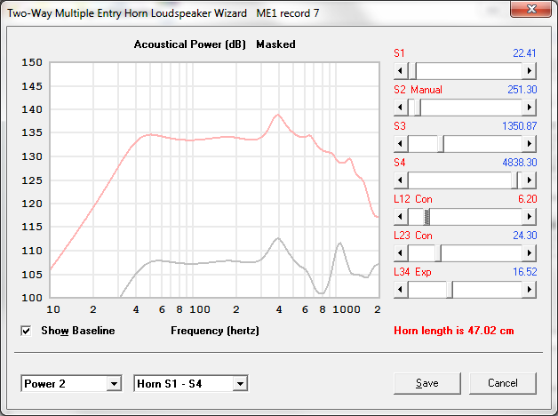
A K-402-Based Full-Range Multiple-Entry Horn
DrWho replied to Chris A's topic in Technical/Restorations
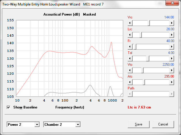
Also, adding a phase plug to your particular design won't be advantageous....it just creates a larger spike that you'll end up attenuating with EQ (and we'd rather not have that acoustical resonance in the system). If you add a phase plug, then the port opening needs to move closer to the throat. Attached are two simulations showing that.