


Erik Mandaville
-
Posts
4571 -
Joined
-
Last visited
Content Type
Forums
Events
Gallery
Posts posted by Erik Mandaville
-
-
GotHover:
"Erik, No the sheild is only connected at the circuit board ground bus and is floated on the VC to reduce ground loop issues. The coax really isn't necessary, but the extra sheilding never hurts."
Sure, that makes sense. As I'm sure you already know, there are numerous approaches to grounding, and grounding in general can be perplexing: what works well in one circuit may not necessarily be as equally effective in another. There have been a couple of instances with preamps I've made in the past where a ground plane, surprisingly, turned out to be a better solution (in terms of noise rejection and ground loop potential) than using a ground buss and/or single-point star ground. Those were scratch built line-stages, though, so at the time I wasn't sure about what the best approach would ultimately be. With a little practiced experimentation, it's sometimes possible to also improve on what is called for in a schematic or kit instruction booklet.
I agree about the use of shielded cable. At line levels (as opposed to phono inputs), I've gotten away with unshielded cable many times in the past, particularly when tube filaments were heated with well-filtered DC and signal leads were routed away from power supply connections. However, where AC is used on filaments, and where input connections may have to be routed more closely to PSU components, a little shielding, even with line level signals, can be beneficial.
I was just curious, thanks for the explanation.
Erik
-
GotHover:
I wanted to stop in briefly before signing off; it's been a long time since I've visited here. I saw your project, and think you did a fine job with it. The chassis looks quite like those used by Transcendent Sound.
I was just looking at your shielded cable leads, and was curious how you've grounded the shields. I see the the input, wiper, and ground connections on the ALPS control, as well as the ground leads that are connected from the pot to the ground buss on the PCB. Are the coax cable shields connected at the ground node connection on the VC?
Erik
-
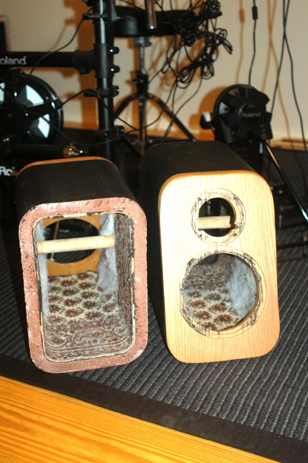
Thanks, Dee. The inside of the cabinets look a little on the oriental carpet side. It's just some cheap, foam-backed carpet that I coated (about 15 years ago) with a thin film of silicone to help deaden the cabinet further. The old poly fill is removed, and new foam will be used to line the entire interior.
I've always liked two-way speakers, and the quality of sound from the little Klipsch XB-10s put me in gear to try another round using some speakers I had on hand. I'm eager to try out the new Vifa silk dome tweeters, but what I heard in the way of HF response from the XB-10s was curious in a good way. The tweeters in those things were really interesting.
I'm not trying to replace anything that I have; just trying some things out using manufacturer-provided specs for the drivers. Hopefully I will learn something in the process, and enjoy some nice sounding music at the same time. I'm going to try an in-line crossover for 100Hz to the subwoofer, which should help with power handling, and to keep the little 6.5" speakers happy at louder volume levels.
Erik
-
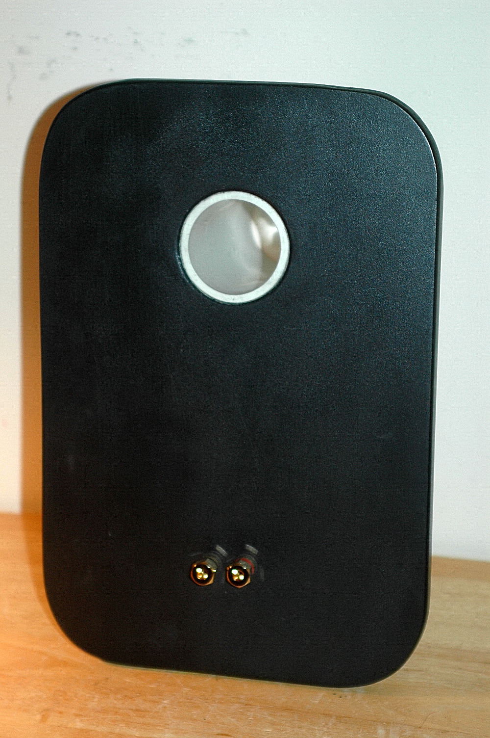
The out side is a little easier on the eyes. The very small two-way speakers that sparked this sudden modification were the Klipsch XB-10s. A really marvelous sounding speaker regardless of its diminutive size. Just for the record, I'm also a K-horn owner.

-
Yes, those are Roland Electronic drums in the background. I did lots of playing in the past in bands, and Marie-Santa bought me a mesh-head set to start to get into it again.
So, the back panels were recut from MDF, the port re-sized and tuned to 50Hz, and glued into the cut-out with the adhesive I've always used for the purpose: Silicone sealant. After three days, the glue was still gummy -- obviously a bad batch. I pulled the ports out, cleaned everything up (PITA). The ports were glued in with another adhesive, and are tight as a drum.
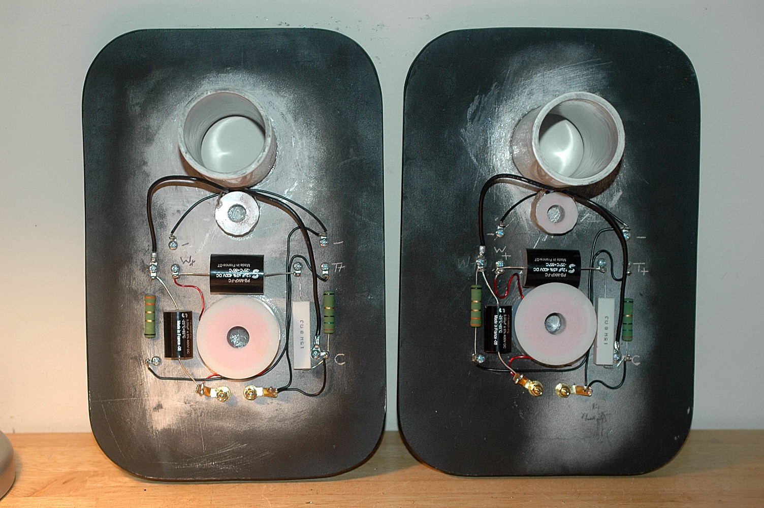
I didn't want to use an outboard crossover this time, which isn't the best for home decore/WAF, but also didn't want to use up any more internal volume by installed the network on another board. Instead, I just attached the parts to the back panel. I built the networks after dinner tonight, and have glued the inductors down with the same adhesive. Mind you, this board will be once again glued-like iron onto the wooden enclosure, and will not lend themselves to find tuning once installed. I'm going to test with foam sealant, and then glue them down once and for all once everything, including the new acoustic foam, is sounding right.
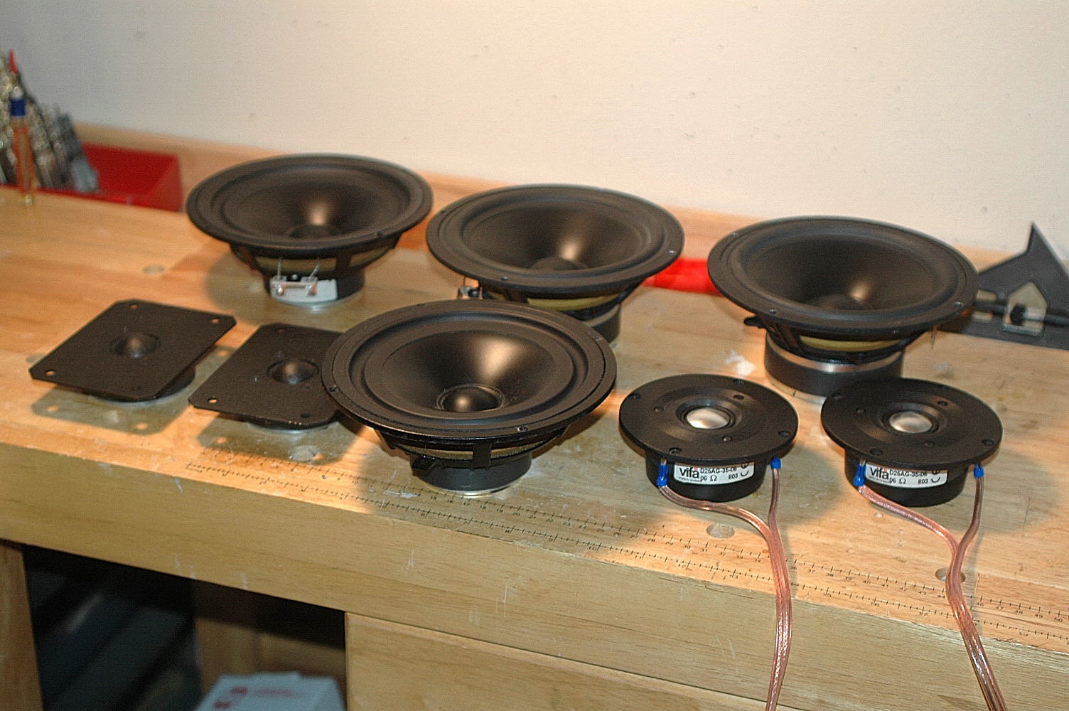
Just for the record: This crossover was originally designed using LEAP (not by me). Testing the two pair of aluminum domes I already had, I found them well, kind of literally metallic and peaky compared to other doped silk domes I've used in the past. However, the one pair of Polydax tweeters seen above, which do have fabric domes, would not fit the round cut-out I had on the front baffle. I thus ordered another reasonably priced pair of Vifa tweeters from Madisound, and they have the same cut out and driver flange dimensions as the old tweeters I was using.
The port length was designed around the net volume of the enclosure, which accounts for the actual space used up by the vent, itself. It should be okay as is, but the old port I had in these same enclosures was about three inches too short.
Since the inside will never be seen, I didn't put makeup on them. The network is a simple first order low pass with impedance equalization, and the tweeter is a second order. I'm using Solen caps because I like a harsh, grainy, and unmusical HF response.
After testing, I'll glue the caps and resistors down, too.
-
Guess work? No. There is a specific way of determing whether a driver is more suited to a sealed or vented enclosure. After once again determining the internal volume (almost exactly 14.5 Liters), an appropriate starting port length was determined, although the final tuning will be done by ear.
Enclosures with old drivers and back panels removed:
-
I walked into the store's listening room and sat down about six feet away from a pair of slender floor-standers. Listening more carefully, I began to realize that the very coherent midrange and treble that even sounded exceptionally good far off axis was not coming from the speakers I thought, but from a considerably smaller pair positioned in the dark above them. Was this a trick to impress, or just a coincidence?
Granted I was only several feet away, but I have been more used to such comprehensive, full sound coming from a pair of 1960's vintage Klipschorns in the corners of our listening room. It seemed to me that based on what I was hearing, a subwoofer was probably part of the equation, and that turned out to be the case. It was rather far off to one side, though, and in that respect kind of discreet. The way these speakers pulled off the vanishing act was impressive. Had I the money on hand, I think I would have bought a pair on the spot.
Knowing I had some extra drivers from some years ago, I went home to my work room with the idea of putting together another two-way system. I have a pair that I made in the 1990s out of ceramic flue tile. They are virtually inert, despite the fact that one might be inclined to think that fired clay would ring. These things are over 1" thick, very firmly braced by a heavy wooden dowel, are almost totally non-resonant. As good as they are, I was inspired by what I heard from those in the store, and I thought I might be able to improve on the situation. It took me a couple of hours to cut through the very tough silicone adhesive that held the back panel to the enclosure, but it eventually came off. I had to remove it in order to change the length of the port for the pair of 6.5" woofers I selected from these:
-
I often see the reference to the contradiction in terms issue in reference to passive preamps. I sort of just thought of that term as a description for a device (which happens to be passive) that is before the amplifier in the signal chain.
Radio Shack has the parts needed to build a simple in-line volume and switching box to get an idea for what they sound like. Having also been among those who have built and used them in the past, the references to source output impedance and load input impedance can't be over emphasized. That is the reason behind transformer-based passives: They provide a comparatively high impedance on the input, yet extremely low output impedance figures on the output to the amps; which in turn in my experience seem to work better with high input Zs. Several months ago I built a small, dual mono control (no source switch) with my Dyna ST70, which has a suitably high input impedance of around .5 megohms. A long, long time ago, someone once suggested that the 50kohm pots (linear taper controls) I was using were totally inadequate for this application, and that I should be using a value of at least 1 meg. So, I tried it, and the results were terrible. They had the situation in reverse, since a pot of that value offered extremely high impedance on the output side, and high output impedances have trouble driving capacitive loads, such as is sometimes created by long runs of high pfd/foot IC.
I agree it's possible to get very good clarity with no additional noise, however, it helps to have a source, such as the generally higher outputs of a CD player (most of which are more than capable of driving many amps into clipping). It's sort of ironic, really, that more often than not active line stages are used to attenuate the signal rather than amplify it. What they do provide is impedance buffering between components, which means that an amplifier will see a lower source impedance from most active line stages than they would with most passive units, except transformer coupled examples. I also once experimented with a sort of passive-active vacuum tube buffer configured for unity gain but very good impedance matching. The problem with that is the need for a power supply, which of course can be a problem in some cases.
With conventional carbon comp pots of 10K, 50K, or 100K ohms, it's possible to install a very small high-pass filter between the input and wiper of the control. This would be in the range of maybe 47pfd, or so (I have to go back and find the actual value I used). It seems to somewhat offset the HF rolloff problems that can be encountered at reduced volume rotations, where the cap is essentially out of the circuit at higher ones. Tube instrument amps have something like this called a 'Bright Switch.'
Fixed resistors can offer better tracking if you're using a single stereo volume control, but it won't provide the impedance matching benefits of a transformer-based preamp. Those can be more expensive than many active line stages.
Have fun, you might end up with something you really like! Again, Radio Shack has the RCA jacks, volume controls, source switch (though they are not 'make-before-break' switches the last I looked), hook-up wire, and small chassis to build one of these in a couple of hours.
Erik
-
The dowel pegs give them very much of a fine-wood-work sort of finish. So. Two pair of La Scalas in such a short time -- pretty incredible. It's amazing to see what someone can do when the will is there to do it. There are some very ambitious and talented builders on this forum.
-
Al:
You're right, about confirming that connection is tight. Scraping off the clear coat was help to me, so I just thought I would mention. Honestly, it's nice to see a well-built pair of these amps. I almost sold mine once, and am really glad I didn't.
Erik
-
You've really been working on these! I think the contrast in the careful trim placement on these looks really good.
Very nice job,
Erik
-
Al:
"a little bit of hum but otherwise excellent amps"
If you haven't already, try:
- Thoroughly re-tightening the screw that hold the ground ring terminal to the chassis. Also related to that: W. Labs did not remove the clear overcoat on the brass plates for that important ground connection. Remove enough in that area so the ground makes solid, metal-to-metal contact, and use a star washer so it bites into the metal.
- Readjust the hum null pot (I know you know that!), but more importantly, TWIST the yellow wires that extend from the out two solder terminals on the pot all the way over to the 2A3 filaments. Those things carry heavy 60Hz current, and twisting can really help with that.
- You have 10,000uf filtering the rectified AC for the 6SN7 heaters. Try paralleling another 10,000 cap of about that same value. Many Moondogs I've seen added an extra cap, and Ron. W. has suggested it to others in the (long distant) past, too.
- The twisted red and black leads are of course from the RCA jack over to the grid of the input stage. Double check the ground connection of the black wire. You can also try using a length of shielded cable intead of that, which might help. The shield is connected at the RCA jack end, but floats on the otherside. However, you still have to have a ground connection for the jack. If it's ground loop hum, there are some safe ways of dealing with that.
- Leaving the speakers connected and the amps off at first, remove the RCA jack connected to the inputs, and in its place use a shorting jack (just any cheap jack/cable can work for this. If you don't have a shorting jack, make one with an old IC cable: Short signal and ground. Plug in that shorted jack, turn the amps on, and listen for noise again. In other words, are the amps the source or something else?
Mike is right about these classic SET amps. They are really very high quality in all respects.
Erik
-
Claude:
"So I never really messed with the original Khorns or LaScalas, just dsconnected the tweeter. While I like the Klipsch heritage sound very much, what I put together (using only my Khorn money the whole time) is FAR superior, sonically, but huge and ugly, hence, the title of the original post."
Absolutely, I understand what you are saying. Truly, there is nothing wrong with modifying these great old speakers in any way one wishes to. I'm using new tweeters myself in ours, but I just like they way Bob's solution works. Some here have thought it cliche' to make reference to the comments of spouses, which is fine for them, but when I was contemplating a complete reconfiguration of our Klipschorn top section, my wife, who is very tolerant and supportive, gently put her foot down. The point was that we were starting to drastically change a design that is already very good, and on which a certain very well-respected designer and thinker had invested a great deal of time and energy. The point is valid, I think, and at the same time I'm guilty myself! I've altered the crossovers (slightly) by choosing to use a resistive L-pad over the autoformer; I've chosen a new tweeter that is quite different from the originals; and thought the speaker sounded less 'muffled' with the grille fabric removed. I've changed them too because the changes I made sound better to me. I also installed acoustic damping material in our Heresies, which to me was an improvement (you just don't know it's there!).
Similarly, the very competent and talented woman who designed our back-loaded Lowther horns suggested to me strongly that I fill all the cabinet voids with sand to deaden the enclosure. With lots of effort I did it, turned the system on, and was met by a sound that I just couldn't live with. To me, it ruined it, even though in my mind I understood the importance of the theory of a loudspeaker cabinet that was as inert as possible. This means that some of what I like about the sound of the Lowthers is, in fact, the way in which the cabinet contributes and COLORS the sound -- just like every single component, passive or active, in the signal path -- sources, preamps (passive or active), amplifiers, transducers (phono and loudspeaker), etc.
The point I have tried to make for too long is that in light of what CAN and has been done as far as manipulating and changing an original and classic design, deciding that a simple resistor L-pad sounds better than a multi-tapped choke is relatively benign. I also am very familiar with PWK's research on this, and still prefer to stick with what sounds best to me -- just as those who have installed different horns and drivers in their La scalas and Klipschorn top hats. To my knowledge, he never published any paper or modification that suggested the use of squawkers and tweeters from companies such as Altec and JBL.
(I say this jokingly).Enjoy what you have, including the experimentation with new components. We all have our own objectives and preferences as far as what we choose to do to make these speakers sound better.
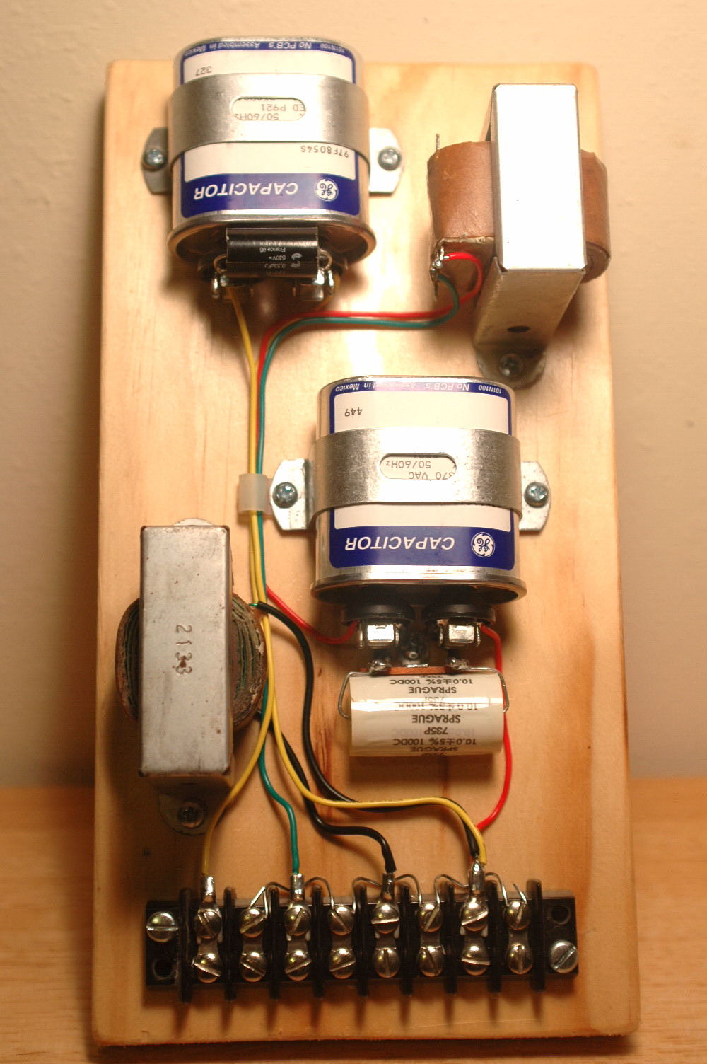
Kevin: On the picture I posted, the leads are color-coded. The yellow connections, that may be a little hard to see, are for the tweeter. There was a schematic of a Heresy II recently posted, where the tweeter section also completely bypassed the autoformer. Interesting, it's also I higher order circuit, which can also have the effect of some insertion loss, which in turn can thus be a way of balancing and equalizing driver outputs. If you don't care for the result (which will probably be subtle), it's always easy to put things back the way they were.
Erik
-
Kevin: For the 3rd order on the type AA, it was for the lower crossover point, not 6,000Hz. I need to look at that again for the different values that would be needed. I know what tweeter you have, and a 3rd order network is actually what is specified, but for 3.5kHz.
Erik
-
Hi, Kevin:
I envy your comparative handful of posts. Honestly. When I see the close to 5,000 of mine it makes me think I need to be doing other things.
So. This is really a very simple thing to do. On the Type A, you remove the connection between tap #5 on the autoformer to its connection on the 2uf capacitor. Leave the other connection on that same cap that leads to the (+) tweeter connection. The now-free side of the 2uf cap (the side that previously was connected to the top of the autoformer) is instead connected straight to the (+) input of the crossover. Another way to make that connection would be to run a lead to the input end (not the autoformer end) of the 13uf capacitor, because it also goes to the crossover input.
For a first-order network with an 8 ohm driver @ 6,000Hz, the calculated series capacitance is a little over 3uf. On the network below to help illustrate this for you, I'm using a 3uf motor run that is paralleled by a .33uf poly film type. You already have the existing 2uf, and can get by to try it by paralleling a 1uf capacitor with it. If you don't have one, Radio Shack sells a mylar in that value which would work fine (just cost too much).
I've been connecting tweeter networks like this, including these old Heritage types for years. Nothing bad will happen -- you'll just think it worthwhile, or not, just as some would prefer to leave it where it is because it sounds 'better' for whatever reason.
The type AA is a 3rd order, which can be done the same way. DJK and I arrived at almost identical values for the three elements needed. Let me double check this, but I'm quite sure the single inductor, which is connected to ground on one end and between the two series capacitor on the other is close enough to what is needed. You would just change the cap values, and you'll end up with exactly the HF branch that I made on the second crossover shown. In both cases, the crossover point is the same, Kevin. It's just simplifying the design by connecting straight to the input, which is common practice.
Like ANY of these modifications, if it's not for you, it's really easy to put things back to how they were.
Erik
-
And FWIW: I have no disagreement or problems with anyone changing their original Klipsch speakers in any way they may choose. There are lots of guys/gals who have altered them with completely different drivers, horn lenses, crossover designs, and so forth. Those are in fact the parts that provide the characteristic Klipsch Heritage sound. My premise is simply that the autoformer is of less importance, IMO, in what it contributed to that sound.
Have fun!
Erik
-
"In fact, funny story, when I was at PWK's house (one fine day in 1985), he was doing just that with his connections and the system was squealing while he was swearing at it, as he was swapping connections in the closet, so he was one to pull RCA plugs on purpose. LOL. He played his own symphonic recordings for me. All the stuff he published, he did. Including the resistor box for the 3rd channel and the 2 false corners. His Khorns and center Belle were oiled walnut right from the factory floor, nothing custom at all............FYI."
That must have been a neat experience! All I had at that time was the literature for the speakers. I longed for a pair of Heresies back then. The closest sound I could find that was like them was a pair of Cerwin Vegas. They actually weren't too bad, but they weren't the Heresies.
Erik
-
"I connected the cap to the autoformer, then the autoformer -4 db tap to the driver. I will try it the other way, then, just to see.
What is better about it?"
For you it may not necessarily be better. To me it was. It also removes the tweeter from any association with the autoformer and input capacitor. That capacitor may be a source of slightly increased series resistance. A more modern way of connecting the tweeter filter, which is how some of the later networks were done, is to connect it directly to the amplifier input, with only the single capacitor between it and the amplifier. It simplifies the design, and may provide slightly more energy to the tweeter. Connected that way, it's a true first order network. As far as autoformers and L-pads: The older designs used autoformers. They worked and continue to work. The newer designs don't use them any longer, although I don't agree it's because Klipsch is trying to focus on profit at the cost of performance in doing so. If what the autoformer contributed to the sound was so significant, it seems to me that the slightly higher cost would be judged worthwhile. Altec and JBL used resistive L-pads, including variable types. It's a design choice, and Mr. Klipsch preferred the autoformer.
If you decided to try the network without it, some changes have to be made to off-set the altered reflected impedance. I prefer resistor L-pads, and I don't agree with the traditional idea that they are inferior. I compared them, and just use what sounds best to me. This doesn't mean I don't respect PWK. In choosing two resistors over a heavy winding of wire, I've actually changed HIS original design far less than those who swap out the entire midrange branch of the speaker, including both the driver and the horn -- along with a new tweeter. I would argue that the midrange branch of a system like the Klipschorn or La Scala is responsible for a signficantly greater percentage of the overall sound of the speaker than does the method of attenuation it uses -- aka: autoformer. That's why I have kept that part of the speaker original. A complete alteration of the entire top section of the speaker weakens the argument, IMO, that choosing a couple of resistors over a multi-tapped choke is invalid. As I said, I respect PWK's choice; I just suppose I process sound differently.
That's all! It sounds like you're enjoying the changes you made. That's good.
Erik
-
Kev: That entire situation is really unfortunate -- I'm sorry it never got resolved.
Al: I did come across those very recently. They look really awesome.
-
"Got rid of the attenuating resistors, Zobel, etc. in the JBL Xover,"
That is honestly refreshing to hear. I have read numerous times where modeling was done with specific reference to this -- where the designer wanted to do away with any circuit that might impose losses. Even at the cost of linear measured response (which in one case I remember had been described as 'boring' and uninvolving compared to plots that revealed certain mild bumps and deviations at specific frequencies. Simplicity can sometimes be very difficult to improve upon, and what is linear may not always equate with 'good' sound reproduction. The other side of the coin always remains, though. Subjectivity is such a significant element in all of this.
-
"Just finished my Xover tweaks today. Get this, I'm running all 1st order slopes, just a 3uF cap on the JBL, wide open,"
Great, I think that works very well, too, and my findings have been the same about the improvement at lower volume settings. Positive feedback did an interview with Bruce Edgar, and I remember in that he mentioned his preference for very simple crossovers, as well.
Did you connect the 3uf cap directly to the input or after the 12uf capacitor at the top of the autoformer? For me, the direct connection is a change for the better.
Good work -
Erik
-
AL: My schematic is from 1998, but there is very little change. Do you still want a copy of it?
Erik
-
Hi, Al:
The Moondogs are generally very similar, although there was of course the change from MQ transformers to EP. I think my Moondogs are the very same vintage as yours, and also use EP iron. The color coding for the output transformer secondary connections is different between MQ and EP, so what I'll send will have the correct color-coding if you ever want to change those.
If you're familiar with the Bottlehead stuff, you can check out some specifics about the 2A3 grid choke. It's used in place of the grid lead resistor, which is connected between the grid and ground. It looks like a small filter choke, and can be attached on a side wall of the amp. They are a little expensive, but for me this is really a design change, not just a part substitution. Since I sold my Horus amps (the grid choke is part of that design), I no longer have them in my Moondogs.
I have to say, though, just like many of these modifications, they are subjective. I see things advertised as 'having all the mods,' which to me sort of means that some things were changed from the original design -- perhaps not necessarily always for the better.
I'll send the Moondog info. today.
Erik
PS: I wish I hadn't seen that picture of the Oris horns. Started me thinking about them again!
-
I have two 2.5mH air cores that can be unwound and measured for the needed inductance (not a guess, I have a very accurate L-meter) at that frequency. Coils and labor: $0.00 payable however is convenient! I'm not using them for anything, and they make the parts bin drawer heavy to pull open!
Erik


Any Will Vincent 6V6 amp owners ?
in 2-Channel Home Audio
Posted
I'm using one of Will's 6L6 Baldwins with a pair of two-way monitors I built a few months ago. I've also used the same amp with our Klipschorns, Heresies, and rear-loaded Lowther horns. The results have in all cases been very satisfactory considering the cost of admission (actually, despite the cost of admission). He also makes what he calls a 'Super Baldwin,' which among some other changes also includes larger output iron. I've heard that version as well, and also own a slightly modified version of his Dynaco ST 70. I'm using Hovland coupling capacitors in the Dyna, although they sounded just a little too bright, perhaps, in the Baldwin. I found a much more suitable capacitor sold by a company called Solen. Will would install whatever a customer wants.
I own and use several higher power push-pull (including the 6v6 mentioned above) and single-ended amplifiers, and the battleship-like Baldwin is great fun and good listening.
Regards,
Erik