


D-MAN
-
Posts
4413 -
Joined
-
Last visited
Content Type
Forums
Events
Gallery
Posts posted by D-MAN
-
-
I find it interesting that the reference chosen to compare its performance against is the Khorn. That's because he clearly wanted to set the bar high. The rest is subjective, but traditionally, a wide latitude is acceptable and even expected in sales pitches as far as having anything to do with reality.
Better looking than a Khorn? Really!
DM
-
Very cool, ELENA. Beware of posting plans on the internet, though, or you will lose all rights and ownership of them. However, please tell us more about them.
What is the Fc of the horn, and what frequency is the port(s) tuned at, etc.?
DM
-
JBL colored terminals are "backwards" with most other "accepted" conventions. I ran mine straight up, no attenuation.
Dana -
Thanks Flemming.
The Smith horn is on hold? I thought you bought the internal flare parts from Martinelli?Dana -
Due to the wavelengths involved for tweeter use, the overall path length of the horn is so short that the vanes would literally have no effect, and there is possibly not room enough in the tweeter-specific horn.
The Smith-type horn is used at lower frequencies, although a 2" throat Smith ought to work with a coax (combination midrange and tweeter) driver, although I don't know of anyone testing this.DM -
The K33E at 8+ mm Xmax is an indicator of that one being faulty. Yes, in general a good horn driver has a light cone and good cone extension.
However, that is just a "rule of thumb". For instance the Altec 515 is quite a bit under that in XMAX, and yet it remains a VERY good-to-excellent horn driver!The IM distortion in a horn is reduced exactly because the compression the driver is operated under naturally limits the extension.Also, the second harmonics generated are substantially subdued in a horn compared to a direct-radiator.DM -
Folks, I am suspicious that those Khorn plans are NOT the current 15" variety, but are the original 1946 version for the 12" field-coil driver, and so will have NOTHING to do with the Speakerlan "K" plans which were kloned from a post-1962 Klipschorn. BE AWARE! Apples an oranges!!!Also, I want to point out a need for a correction:First, the post with the recommended specs is WRONG! It should read Qms, NOT Qts!!! You GENERALLY SPEAKING don't want a high Qts in a horn driver! You want a lower Qts (i.e, ,<= 0.30, etc.).There are 2 LIMITING ISSUES in the Khorn concerning the appropriate driver:1) throat cavity opening size compared to max. available throat area2) available Vb (back chamber volume)The small slot used in both the post-1962 Khorn AND subsequent Speakerlab Klone is 3x13" or 39 sq. in in area. The available throat cross-secional area is 78 sq. in.The Vb is approx. 3900 cu. inches.Then the overall Fc of the horn 38Hz per the AES "Jubilee" paper.The K33E specs do not work "well" using T/S formulas because they are a large volume driver (i.e., 11 cu. ft Vas) under quite a bit of compression (Vb= 3900 cu. in.). The relatively low Fs (<=34 Hz) allows for a gradual roll off below the Fc of the horn and allows for a sufficient roll off above 400 Hz (or so) in order to use a first-order (6db per octave) crossover slope. Note that it is definitely NOT fully reactance annulled.If you use the Crites driver or the K33E, use the smaller slot size. Generally speaking, for all others, a wider slot is recommended. The choice of either of these drivers allows you to use the stock or aftermarket Klipsch drivers and crossovers. Otherwise, you are going to be on your own.DM
-
No, guys, I don't have an SK, that picture is Chris's, but now I don't exactly remember which Chris, but he's here on the forum somewhere!
I'm just an interested bystander. John, yes, Speakerlab came out with the new version sometime in the 1980's (which I seemed to have missed), since my "K" plans are from 1978. I don;t know when they quit making them, either, but I would guess early 90's, but that's just a guess.
DM
-
Here's what I'd do if it were me, this is one of Armando's designs...

-
Some "new" SK info, i.e., drivers employed.
-
How about just doubling up on the cones, wired in parallel, and attenuating both as needed. That would double the output (halve the power handling?) and Bob's your uncle!
Technically, cone midranges are a perfectly good approach with some great attributes. It never seemed to catch on IMO because PWK didn't do it first.
I would daresay that the SK cabinet is about as good as your ever going to get as far as being an anti-diffraction "device" for the midrange, too. It's not a bad design at all.
I would think that its attributes actually out-perform the Klipschorn, depending on the quality of the crossover, IMO which is probably the best thing the Klipschorn has going, competitively speaking.
Again IMO, it's an underrated design, and really embodies some substantial improvements while retaining (or surpassing) the classic Khorn bass response.
DM
-
Ah, the "new" 1980's SK vs. the old "K".
Like this?
DM
-
JC, negative, I'm at home and haven't been to work. Call me.
Dana -
In the 90 degree turn at the front corners (e.g., Jubilee), the goal is to turn the waveform 90 degrees into the axis of the side channel(s), which would be a 45 degree reflector. A 67 deg. reflection angle would in effect aim the reflected waveform at the channel wall, not the channel center axis. You want to go with the center channel axis to keep side wall reflections to a minimum, otherwise you would just be introducing more inter-channel turbulance that you don't need or want, of course.
However, like I said before, it doesn't really matter whether its a radius (partial) reflector or a full-channel reflector. It would only effect the upper-bass frequencies if at all - HOWEVER - it certainly won't hurt having full-channel reflectors and might possibly help. Being that the Jubilee can naturally make use of upper bass frequencies, why not make it as easy as possible to propagate them through the horn?DM -
Well, that's quite probable. One shadow area that I know of, for example, is the Khorn/LS/Belle throat cavity opening is smaller by 1/2 than the throat area cross-section, that would have some diffraction events associated with it. Interestingly, the diffraction would be in favor of the bifurcation taking place at the same point. Sort of using the inevitable slot diffraction to "aid" the turn. Conjecture on my part, but I know it's there.
DM
-
-
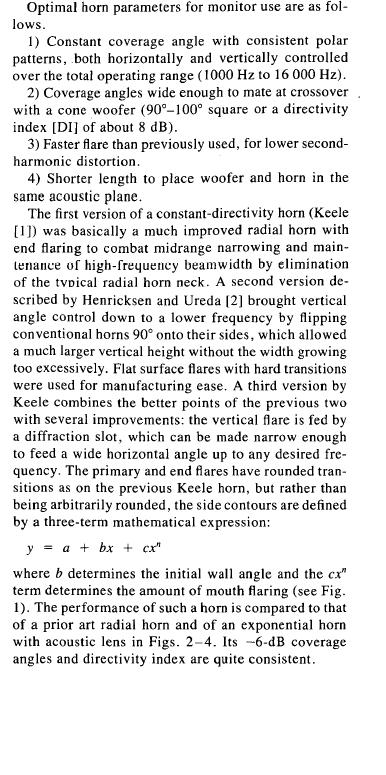
Please re-read the quote you clearly didn't get it the first time. Also, the parameters/characteristics I stated above are all consistant with the commonly-called "CD" horn.
However, the term "CD" as applied to horns is a misnomer, or more of a marketing tool, but I digress.
The attachment is an excerpt from the JBL paper on CD horns, and outlines some of the properties/characteristics that I mentioned previously.
DM
-
All I would want is the horns, only. B&C drivers? Bah!
As for "beaming", in a single-throat exponential or in this case, tractrix, a close-relative with an even tighter flare, yes, I would expect that it would have a tendancy to narrow in dispersion pattern as dictated by the general proportions of the horn walls flare. That is not a CD design, although its rapid, wide flare and very short length would promote a fairly wide dispersion angle even at extremely high frequencies. I would be surprized if the horn in question actually displays a disagreeable tendency to beam.
Ameliorated in some designs, though partitioning, or multiple flares, etc. but never truly rendered moot. It is a matter of physics, and for one tradeoff, there is always another.
Here is the quote from Olson:
It will be seen that up to the frequency at which the wavelength becomes comparable to the mouth diameter, the directional characteristics are practically the same as those of a piston of the size of the mouth. Above this frequency [smaller wavelengths], the directional characteristics are practically independent of the mouth size and appear to be governed by the flare.
<?xml:namespace prefix = o ns = "urn:schemas-microsoft-com:office:office" />
This means that the smaller the mouth, the wider the dispersion for frequencies lower than the l=m ratio, and the narrower the smaller wavelengths become until they match the flare.DM
-
I don't know where diffraction events would be important INSIDE a well-designed horn channel per se, but certainly takes place once the waveform leaves the horn channel(s).
Do you have any specific examples in mind?
DM
-
Hasn't anyone resolved this? The wing needs airspeed to create lift. So it is simply down to the speed of the air over the wing whether the plane in question flies or not.
The confusion seems to lie in whether you think either the plane is moving through the air, or the air is moving over a stationary wing. Either would cause lift if it results in enough air moving over the wing(s).
If you think that a jet engine SUCKS enough air to cause lift on a stationary wing, then you are wrong. The engine produces thrust which moves the airplane through the air, whether on the ground or in the air, it is the movement of air over the wing that causes lift. The velocity of air at the respective jet intake is far less than the accellerated and expanded air velocity (and volume) at the exhaust.
If the airplane was prevented from moving (as when the forward movement resulting from the thrust is counteracted by an equal force in the opposite direction) by a moving conveyor, the plane itself remains stationary, and that means no air speed over the wings. It doesn't matter that the wheels are free-wheeling, it is the motion of the plane THROUGH the static air that matters. And in the case that the conveyor is turning the wheels in an opposite direction at a speed to cancel the force of thrust, the plane remains stationary in position.
The fact that a conveyor running the opposite direction at equal speed to cancel the effects of available engine thrust would also prevent enough lift to get the airplane off the ground, as the amount of air moving over the entire airfoil would be insufficient to allow flight. Like I mentioned before, zero airspeed = zero lift.
You could, however, achieve flight from a stationary position in a wind-tunnel, providing you have generate enough wind. It all comes down to airspeed over the wings.
DM
-
How much did these cost, and how-and/or-who do we call to get a pair? Very intriguing - these are 2" throats?
The high frequencies are going to be limited in dispersion characteristics by the actual physical flare angles of the horn once the wavelength is small enough to fit inside (or across) the horn mouth (per Olsen). This happens in all HF horns, though. I'm not particularily bothered by that in this case, in that the horn in question is so short and the walls are fairly straight with a very wide flare. My concern is mainly the midrange dispersion characteristics and whether they actually go down to the Fc.
I'd love to give these a listen!
DM -
Hear is what I am thinking. The full channel reflector may extend the high frequencies but at the expense of efficiency of the lows. So if you are going to crossover in the 600 range wouldn't it be better to use the partial reflector to preserve efficiency? Roy am I way off base?rigma
By all accounts, low frequencies are relatively immune to reflectors due to their very long wavelengths. At best, reflectors only effect the mid and upper bass frequencies where the wavelengths (or sub-multiples) are shorter, respectively.
The full-channel reflectors as put forth by Bruce Edgar (for example) are intended to preserve phase relationships through the folds, again effecting only the upper bandpass.
The low frequencies will not be effected by reflectors.
DM
-
It only REALLY matters which approach YOU think is better!
Myself, I would also go with full-channel reflectors in the Jubilee front corners, since its design is particularily concerned with a high mid-and-upper bass frequency bandpass.
However, it certainly is not a show-stopper if its a radius-style reflector instead, as in the AES drawing.
DM
-
It is completely understandable that KlipschCO finds it "unrewarding" to publish FR curves. The well-known competition doesn't even bother to publish ANY specs about its products at all, claiming that any specs are virtually useless, confusing, and unimportant (more or less).
As a matter of fact, it just shows the level of discernment that Joe and/or Nancy Blow are capable of mustering when purchasing an audio product.
Getting their money away from them doesn't take specs of any sort any more. It's a WalMart world now.
Not Klipsch's fault!
DM


Wow! Another one (I'm working on a 3rd!)
in Technical/Restorations
Posted
A low-pass tuned filter on the side of the horn channel preceding the reflex port? Interesting! I haven't seen both used in the same horn before (I assume I'm understanding it right).
DM