

dbert
-
Posts
47 -
Joined
-
Last visited
Content Type
Forums
Events
Gallery
Everything posted by dbert
-
Get a good magnifying glass and some good light and look at the pins real close. It’s a small slot with super small pins. Does the jack feel loose on the board? If you don’t find anything bent or loose the pins may just need a cleaning. A good (plastic safe) contact cleaner or deoxIT with the right brush would be ideal, but alcohol and an acid brush might work.
-
I just thought I would chime in with an update. Seven or eight months later and mine are still working fine. I still have never used the standby function for any long duration though.
-
Way to Make IFI compatible with latest gen Ipod Touches?
dbert replied to gbm22's topic in Personal Music Systems
This is the other side, but same points. -
Way to Make IFI compatible with latest gen Ipod Touches?
dbert replied to gbm22's topic in Personal Music Systems
Sorry for the delay. It will be at least one more day before I will be able to try this. -
Way to Make IFI compatible with latest gen Ipod Touches?
dbert replied to gbm22's topic in Personal Music Systems
Im listening! -
Wait. What end were you having to hold a certain way to make it work? The dock or the amp/sub? Sorry. Reread what you said. Dock end. Disregard.
-
I have some promedias that had a problem with the Din connector. If the pins look ok check the the printed circuit poard to Din connection for broken solder joints. http://forums.klipsch.com/forums/p/113932/1147209.aspx#1147209
-
This is bad news. This means it's not just a vendor choice for the original capicators, but a design flaw that kills capicators.
-
Interesting. I have not used the standby feature for more then a few seconds at a time since I replaced the capacitors. I've left it powered up for how ever many weeks it's been now, but have just turned the volume all the way down or turned off the audio source. I seriously considered disabling the standby button when the dock was apart, but you need it to turn the unit on after power-up (make the led fwd of vol wheel (knob in my case) green). Keep us updated. I wish I had an occiliscope to see what goes on in standby.
-
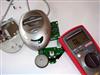
It may well be that the one 25V cap is all we needed. The 4 larger capacitors are used by the 18 volt 5 amp transformer output (yellow/black/yellow wires), and this one smaller cap is for the 10 volt 1 amp winding (pair of brown wires). It appears this 10 volt circuit is what feeds the dock. Rather certain these are just AC to DC power supply rectifier smoothing capacitors. If they are crap though, I am glad I changed the other 4 also. Bottom of board marked up to show basic paths.
-
By the way...for those looking for tips on how to DIY. This has some nice photos and info. http://www.capacitorlab.com/replacing-motherboard-capacitors-howto/index.htm
-
All the values look correct to me. Found a bunch of 63 volt cap photos here. Many similar but nothing exact. http://www.sportslinkup.com/shop/0-Capacitor-63v-1.html What makes you think they need replaced? Electrolitic capacitors built in the early to mid 2000 range are always suspect, but these? I fear you may be just making work for yourself. I could be wrong.
-
Way to Make IFI compatible with latest gen Ipod Touches?
dbert replied to gbm22's topic in Personal Music Systems
I'm wondering if this could be done internally to the dock. With all the test pionts to the 30 pin connector it looks like soldering some resistors in the right places could make it happen. http://pinouts.ru/PortableDevices/ipod_pinout.shtml Just need to find the right locations to solder stuff. -
My Sub is all assembled. Do you have close-ups or can you tell us what is printed on them? The Evox Rifa type sound like a premium product.http://www.audiocap.net/EvoxRifa.htm I’m not 100% sure what happens with the mute/standby switch is selected but I’m going to avoid using it at all. I have my suspicions and I wish I had an oscilloscope. Sometimes I may think it will only be for a short duration (say the phone rings) but I may then forget and leave it like that overnight or something. Switching it off on the back would surely save electricity. As I said I’ve just been turning mine all the way down or turning off the source when not in use. Mine is real easy to turn down now.
-
Glad to hear this is working for others. Because these were so large I trimmed off a majority of the nubs on the bottom with some flush cut diagonal pliers first. Just to remove some of the lead and the bulk of the existing solder on the bottom side. I then heat “say” the positive lead as I put pressure towards the negative lead. When the solder is melted you can tilt the cap and pull existing lead thru the pcb a ways. Then I heat the other lead and put some pressure the opposite direction. Just walk them out one lead at a time. It can take a few back-and-forth’s on each one. I took them all out so I had more room to work cleaning up the holes and putting them back in. You just need to remember which side is positive and which is negative (with stripe). Also, when they are removed there is a little “+” symbol printed on the board under the cap showing polarity. I also use soldering braid to try to remove as much old solder as I can. Removing the old solder and opening up the holes is always the hardest part for me. Remember to be gentle going back in as you don’t want to force it and break the pad away on the board. See if there is some television repair guy still around. Look for some armature radio folks. They almost always have the tinkerer in their midst with the skills to do this. Put an ad on craigslist. I’d love to tell you to do it yourself. It’s not really that hard, but if you haven’t used the iron before you may want to find some junk motherboard or other electronic part and remove the caps and clean the holes there first. There is a lot of general soldering technique info on the web. I’m not going to risk putting mine in mute mode. I’ll just turn it down. I mounted a knob on my dock. It’s not real attractive but it’s much easier than the partial wheel.
-
Yes. My symptoms were as described in the first couple posts back on page1of this thread. Random volume/balance. I am not convinced it’s fixed even though it’s working fine (72 hours now). Three years ago when I replaced the dock it worked for quite a while and I thought it was fixed, but then it started again. I can’t suggest everyone run out and change their big capacitors and all will be well. None of the caps had visible problems until I looked at it a couple weeks ago. I dug it out of the garage and saw the electrolyte leaking from the top of the large 25 volt one.
-
Digikey did not have any Panasonic “FC’s” for the 35volt locations. The 25 volt Panasonic FC was available. I wasn’t ready to trust Nichicon yet and I wanted to get the order going so I ordered all Panasonic NHG series. The 35 volt "Nichicon FW" audio series are available from Digikey but they don’t have any 25 volt versions available. http://search.digikey.com/scripts/DkSearch/dksus.dll?Detail&name=493-3178-ND and the 25 volt "Panasonic FC" is at; http://search.digikey.com/scripts/DkSearch/dksus.dll?Detail&name=P10289-ND Probably best to split manufactures and just order these if you are going to order from digikey. BTW... 48 hours now and still good.
-
I replaced these 5. Qyt 4 4700uf 35V ..... digikey part number P5558-ND Qty 1 4700uf 25V ..... digikey part number P5547-ND $14.71 shipped Not sure they were the best, just what I picked. Added some pics at http://www.justwebspace.com/G2/thumbnails.php?album=1 As to the how, you need some soldering skills. Not a ton, but some. Check the recapping tutorials at badcaps.net http://www.badcaps.net/
-
Running 24 hours now. So far so good. I enjoyed the crap out of listening to them today. I remembered why I could never bring myself to throw them in the trash. I’m not going to say they are fixed for sure, but my fingers are crossed.
-
Got the new caps in the mail today. Just the 5 big ones. Replaced and running. I'll let it run overnight and report back.
-
Just measured the larger cap sizes. The 4 larger 4700µf 35Volt are; 18.00mm Dia, 35.50mm Length with 7.50mm lead spacing The smaller 25v one is 16mm X 31.5mm also has 7.5mm lead spacing. Ordered some Panasonic caps from digikey. I'll let you know how it turns out. Wondering about the health of the other dozen smaller Rifeking caps in the sub.
-
Interesting timing for your post. I dug the sub out of the garage over the weekend and saw that the 4700µf 25v is now leaking from the top. If anybody has the time, it would be nice to list good replacements (i.e. rubycon) by part number. Something one could order a set from say digikey or mouser. I'm going out of town in a couple minutes or would do some research myself. Looks like there is room for a larger 35V unit like the other 4 on that board. Just replace all 5 with same p/n ok? Wonders what the health of smaller caps in there are like.
-
My thoughts regarding the challenge in replacing the LM1973 were not so much in soldering the new one but desoldering the old. Will keep an eye out for your update on the capacitor replacement.
-
I’m not sure I understand what your initial symptoms were. Your first post says Can you elaborate more? What are rsx’s. Sorry, I just don’t understand.That must have been a big job replacing the LM1973. Thanks for taking that off the list for the rest of us.I’ve not seen a radial cap replaced with an axial one. Shouldn’t matter I guess. You must have the polarity correct since they didn’t blow up. I don’t remember seeing any swelling of my caps when I looked last. Keep going and perhaps you will figure it out for all of us.
-
Is there no simple data reader for this type serial bus? Ok, I just realized how stupid that sounds. No databus reader is so simple you can pick one up at Wallmart. It's just 16 ones and zeros in a row. Many never used (always zero) Can it be that hard to read/inject? Where are the electronic guru’s?