


sootshe
-
Posts
571 -
Joined
-
Last visited
Content Type
Forums
Events
Gallery
Posts posted by sootshe
-
-
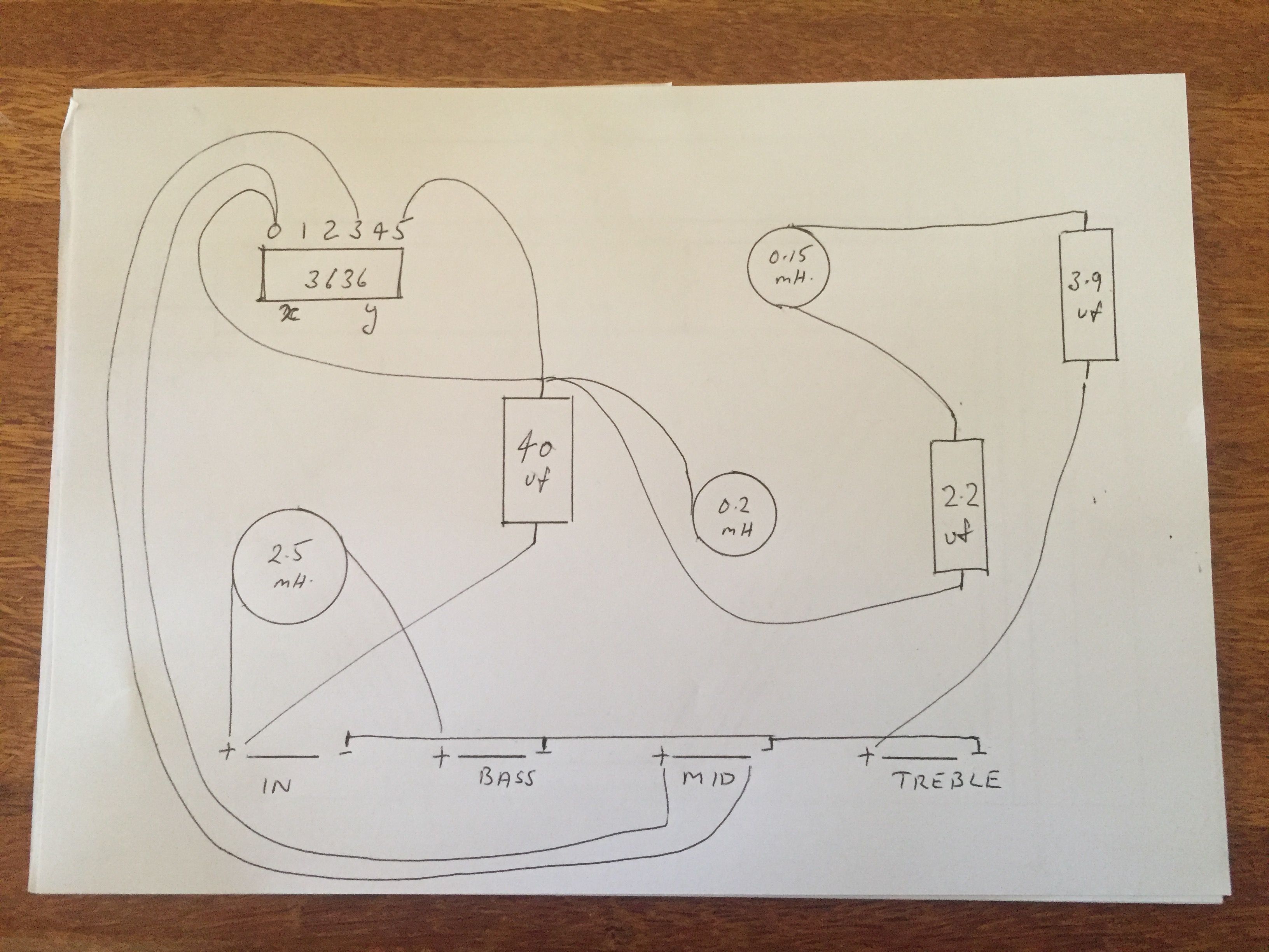
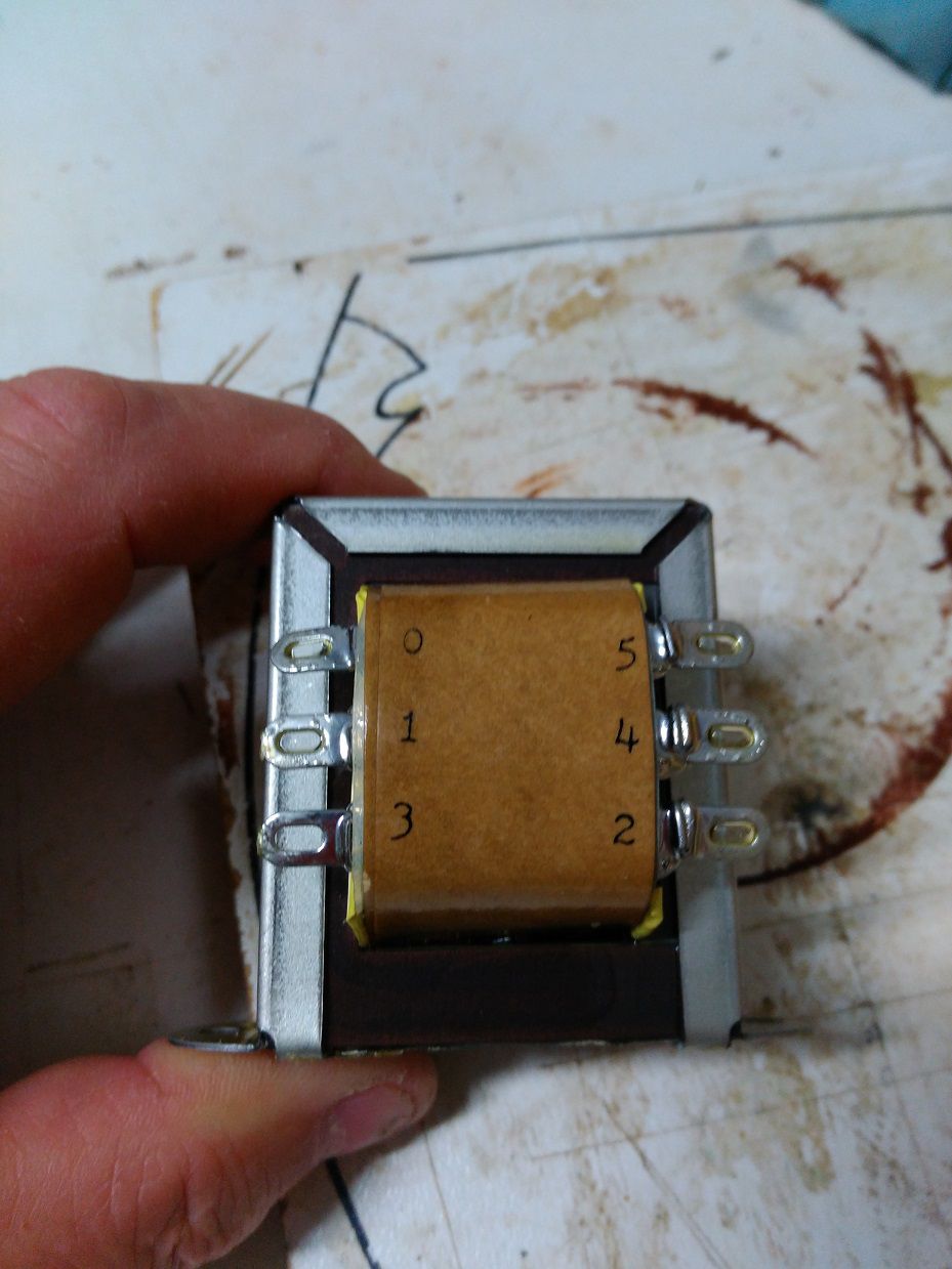
Do you mean like this?

-
45 minutes ago, ClaudeJ1 said:
For which speaker? The + on your midrange speaker goes to a number tap on the Autoformer. The Minus on your midrange goes to the Zero on the autoformer. Looks like your capacitor value to the Autoformer is could be the wrong value depending on what frequency you want to block/rolloff.
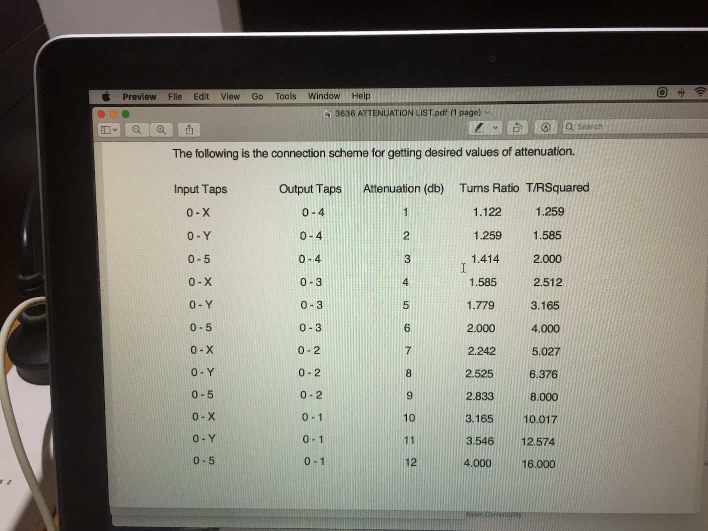
Also, your drawing of the Autoformer is incomplete and should show X and Y as inputs also, along with the 5. Just tell me how many DB of attenuation you need and I can tell you how to do the input AND output on the Autofomer. The 10 ohm resistor keeps the impedance that the amplifier sees as a constant 8 ohms. The Tweeter and woofer have no attenuation, only the midrange.
Hello Claude,
This is for a set of Belles with Crites cast frame woofers, A55G mids & JBL 2404 tweets.
I think -6db would be a good starting point for the mids.
I think I understand where the mid driver connections go to, so that I am able to adjust the attenuation (the outputs from the crossover)....it's the inputs that I am not sure about... where to connect the wires from the .2mH inductor & whatever else connects to the input.
Looks like your capacitor value to the Autoformer is could be the wrong value depending on what frequency you want to block/rolloff.
I didn't think there was a cap going to the 3636? This is where I need help.....am I connecting everything correctly?
Thanks for your assistance.
-
Need help from the experts.
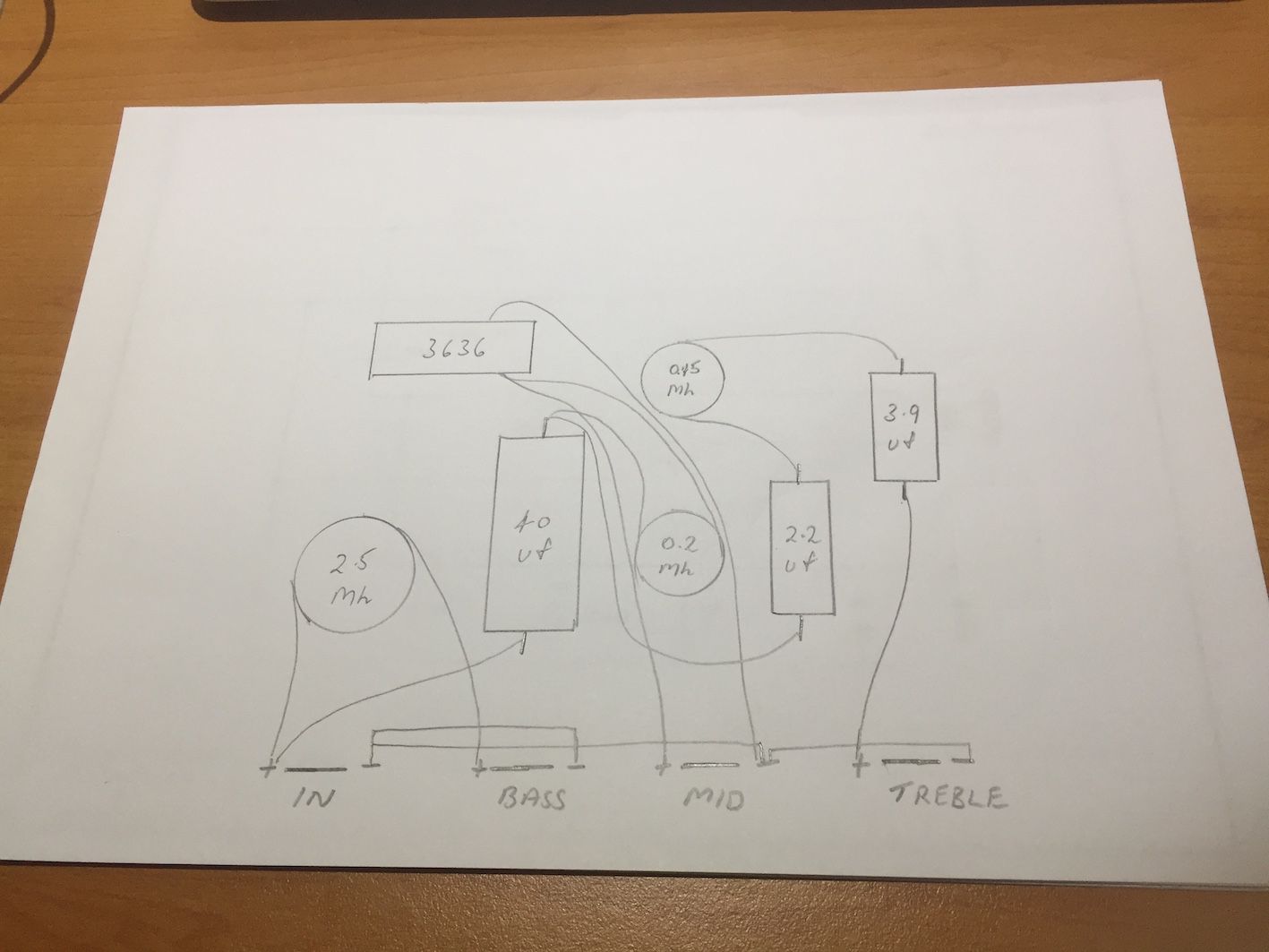
I've settled on the attached schematic design & can anyone help me to confirm the layout I have come up with from this schematic?
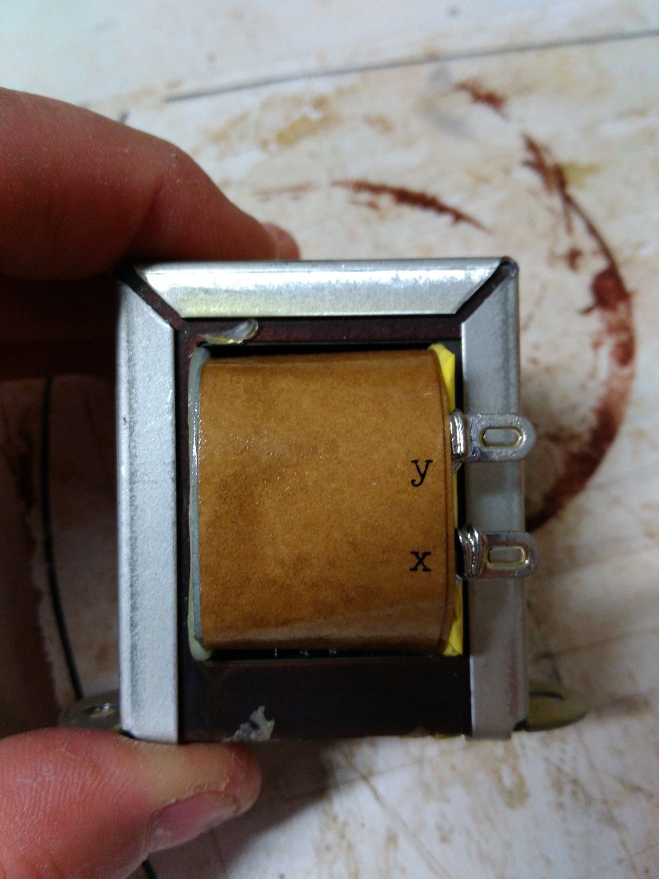
I'm not sure about the connection to the 3636 auto former.
-
Need help from the experts.
I've settled on the attached schematic design & can anyone help me to confirm the layout I have come up with from this schematic?
I'm not sure about the connection to the 3636 auto former.
-
Ahhhhh....too many options! They are a work of art though....very nice.
I'm on the last leg of my journey & have been through active systems before & am now simplifying things. I now run an integrated amp & just need some big friendly fellas that can loaf along without any fuss & not have a room full of cables.
It's all fun though.
-
 2
2
-
-
1 hour ago, mboxler said:
I would think 2.5mH would be okay. This is an electrical low-pass filter. The natural rolloff of the loaded woofer plays into it as well.
I have Khorns. Perhaps someone with Belles could jump in.
I see the ALK Jnr uses 2.5mH & the 40uf cap. It adds a .2mH for the squawker to stop it running full range & has different value caps & inductors for the tweeter section.
-
15 minutes ago, mboxler said:
Nice!
Just to be clear, the 48uf capacitor will get you around 400hz to the squawker. For 500 hz, use around 40uf. For 600hz, 33uf.
Mike
Oh, I see. Thanks.
The Belle will go nicely up to 5 or 600Hz with the Crites woofers, so will choose one of those crossover points.
Does the inductor stay the same at 2.5mH?
-
Here's a link to the La Scalas I built....I think the original build thread is a bit too old....I couldn't find it, but this will give you an idea.
-
11 minutes ago, mboxler said:
What Klipsch model are you putting it in? Is 400 hz the desired cross?
I'm building a set of Belles.
Mid horn & driver will be either the Elliptrac 400 or the Fastrac with the A55G driver, so crossover can be say, 500 or 600Hz.
Something like either of the attached.
-
2
-
-
30 minutes ago, mboxler said:
So the stock crossover has no user adjust for the squawker?
Well, you can adjust it, but the corner frequency of the stock 13uf capacitor will no longer be around 400 hz.
I'd like to keep the 13uf cap rather than going to a 40uf, cap as it keeps the cost down. So are you saying in this scenario, I can't change the squawker level....that it has to be just one particular setting??
Same answer as above, unless you add a resistor across the squawker. If you want the corner frequency of the stock 13uf capacitor to be around 400 hz, the load across
taps 0 - 5 has to be twice the impedance of the squawker, or 29 ohms. If you move the output to taps 0 - 3, the impedance in quadrupled (58 ohms). A 14.5 ohm resistor in parallel with the 14.5 ohm squawker gets you to 7.5 ohms. 7.5 times 4 = 29 ohms across taps 0 - 5.
So if I change the cap value to 48uf & put the 10ohm resistor in, I can use any tap I want....like in the ALK design??
Yes.
& in all these scenarios can I use the 3636 auto former??
Yes.
Thanks so much Mike....sorry I'm a bit lame on the heavy technical stuff, but I do have a reasonable grasp of some of these things.
I will go with the 48Uf version & the 3636 as that's what I'm familiar with from building & using ALK uni's & AP12-500's.
Thanks so much again for clarifying.
-
1 hour ago, mboxler said:
The stock Type AA crossover needs no resistor, as the load on the 13uf high pass capacitor is twice the impedance of the squawker, which is across taps 0 - 4.
So the stock crossover has no user adjust for the squawker?
If you want to keep the 13uf capacitor and use a different output tap number, then you need a specific resistor value across the squawker.
The 16 ohm resistor placement in the schematic looks weird, but it will work for output taps 0 - 3. I would use a 14.5 ohm resistor, but that wouldn't change things that much.
I'd like to keep the 13uf cap rather than going to a 40uf, cap as it keeps the cost down. So are you saying in this scenario, I can't change the squawker level....that it has to be just one particular setting??
QuoteIf you want to choose any output tap number, you need to replace the 13uf capacitor with 48uf (I use two 24uf capacitors in parallel), and put a 10 ohm resistor across taps 0 - 5. You could also add a 35uf capacitor parallel to the 13uf capacitor. The 10 ohm resistor keeps the load somewhat constant regardless of the output taps used.
So if I change the cap value to 48uf & put the 10ohm resistor in, I can use any tap I want....like in the ALK design??
& in all these scenarios can I use the 3636 auto former??
QuoteI hope that helps.
Mike
-
Thanks for that...but my question relates to the adjustment of the autoformer to reduce the mid level. In the ALK designs there is a resistor across the autoformer that I have read is required to enable you to adjust the auto former levels.
It connects to the taps of the auto former. Is this required for this type AA crossover design?
See attached pic of ALK uni.....& there's a resistor across the auto former of the ALK Jnr as well. .
-
29 minutes ago, geoff. said:
Some use the resistor to attenuate the level to the driver.
Others change the cap and autoformer tap values to achieve “similar” results.
There was great thread recently about that.
If I can find it...
Yes.... a bit confusing. If I remember rightly they were saying you need the resistor to enable you to adjust the autoformer to it’s different values. Thanks
-
32 minutes ago, geoff. said:
There was a pair listed in garage sale a while back. The inside of the horns were painted red, but that’s no big deal.
It was still there a couple days ago when I drifted away from reality for a bit and pictured them in an as yet unbuilt tophat.
I’d like to do some in a natural timber finish. Have emailed Dave to see what he can do.
-
2 hours ago, Wirrunna said:
sootshe, Dave Harris email - fastlaneaudio - at - aol.com
The postage to Oz is expensive.
Thanks...... yes, I’ve built a couple of pairs before, but the end result is worth it.
-
Researching a build of the type AA & from what I can gather, when you use the auto former you should have the resistor attached to it.
Attached is the schematic & I can't see any resistor attached to the auto former.
Am I correct in that you can substitute a 3636 for the T2A? & should there be a resistor added to this schematic?
Attached are some photos of DeanG builds that I want to replicate & I don't see any resistor there either.
-
Here's the slot loaded picture.
-
Does Dave Harris still do the Elliptrac horns?
Tried searching for his Fastlane Audio site but found no results.
-
Here you go...Belle_LATEST.pdf
-
1
-
-
-
5 hours ago, Dave A said:
Well finished and fired them up today. One of my La Scala test songs is 2Cellos Thunderstruck. At fairly loud volume regular La Scalas just squall through this. Not a hint of squall tonight and the articulation is pretty amazing. I am thinking this is clearly better than mid braces which is way better than stock sides. I ended up missing supper because fiddling with a bunch of songs with a grin on my face was more fun.
Great job.....enjoy!
-
2
-
-
1 minute ago, RandyH000 said:
------as time passes , we lose some threads ----as they can only keep so much , your Lascala 2008 Thread is still on The Forum
Can't believe it's that long ago that I had those.
I've got the itch again & thinking about a Belle build.....always loved the look of that speaker.
-
2
-
-
On 7/28/2020 at 11:20 AM, MookieStl said:
Do your gentlemen hear this resonance at all volume levels? I am not sure I pick up on it even at high volume. My one pair are LSi splits with the fibreglass and aluminum trim so maybe they don't misbehave as much? My other pair are standard LS but have been duratexed and alum trim added which may help as well.
I may do the bracing to my regular pair to see if I hear the difference. I move both pair around often so dont want to add any more weight. It seems they get heavier every year without adding anything.
You will hear the resonance at low, as well as high volumes. It changes the tone of the bass at all levels. With the added bracing & mass to remove the resonance, the bass is cleaner, has a purer tone.
-
2
-
-
On 7/28/2020 at 12:23 AM, Coytee said:
Are those reflectors back in the rear corners, helping to cut the 90 degree angle? Or is it just the way I'm looking at the picture?
Yes, I put 45 deg reflectors in the rear corners to help smooth the air flow.
-
1
-


OK, I'm stupid....need help with layout from schematic.
in Technical/Restorations
Posted
Do you mean like this?