radiogram
-
Posts
142 -
Joined
-
Last visited
radiogram's Achievements
Forum Veteran (4/9)
14
Reputation
-
On June 24.2022 I asked @Chief bonehead permission to post CW III Schematics since CW III is no longer in production, and he gave me permission and directed me to the post the same in the Crossovers part of the forum. In continuation of that permission, I posted the official Rev-A H3 schematics subsequent to @net-david posting official Rev-C of H3 schematics. I was not aware of the policy change until @Invidiosulus pointed out yesterday. Besides I do not understand how sharing schematics and that too what Klipsch Parts gave out, would violate the new policy. Anyway I just want clarity as I respect this Forum and I do not want to violate anything in future.
-
@Travis In AustinMay I now why the official Heresy III schematics versions posted by @net-davidand me were removed? Thanks
-
@net-davidWhat I am surprised is the amount of difference in the Mid Section particulalry between the between CW II and H III. They both use same drivers and same crossover points on either side. I thought only diff would be level matching L-Pad. But on my own experimentation with 3-dB L-Pad for CW III I could not get uniform 3dB attenuation in fact attenuation above 12Khz Started to increase and was about -4.5dB at 16Khz. So I am guessing that is why maybe Klipsch has different mid section network for H III vs CW III
-
@net-davidBTW I have on a few occasions requested H III network and a like me few others as well. But you are the first one to actually go to the source and get it and post it. Really appreciate it. I believe version yours is circa 2009 or greater as the Resistor is 20 ohms in the mid section
-
@net-davidIt appears to be the first version as the date is Sep 2005. Could you tell me how to contact Trey Cannon so I can get circa 2009 schematics? Thanks Again
-
@net-davidThe other thing I request you is to re-check is the polarity of K53Ti. In CWIII it is reversed compared with Woofer & Tweeter. But not so as per your observation. Thanks
-
@net-davidAwesome. Thanks a Lot!. I just want you re-check this. Based on CWIII Xover it seems to me in the Woofer circuit, that the following 3 parallel caps C1, C2, C3 should be between L2 and R1 and C4 parallel to K28-E. If you look at the CW III Circuit I Posted in June 25th in Page 16, you will see why I am asking this. Thanks and I do appreciate the efforts. Cheers!
-
@net-davidI measured the inductors in my CW III network. Pretty straight forward. That is how I was able to post the CW III network. But just to be very sure I de-soldered one terminal of each inductor and then measured to avoid any interference from any component that me may be connected to the inductor in parallel. BTW, it seems to me in K53 circuit you posted, the three parallel caps should be in series between the inductor and resistor and the capacitor you have shown to be in series between the inductor and resistor should be parallel to the K53. Can you re-check this? Thanks
-
@net-davidCan you also post all the Resistor Values? Thanks
-
@net-davidThanks for your post. I have been looking for H III schematic for quite some time. I am currently using CW III network for my H III upgrade from H 1.5 and bi-amping to reduce Mid & Tweeter level by 3 dB. I hope you get to measure the inductors and post a complete schematic so that I can mode my CW III network to be exact H III one. BTW, I thought the mid & high section will be identical (except for level matching resistor) between CW III & H III as they use same drivers and crossover points and I am surprised they are a bit different in terms of component values. Thanks
-
@Bacek Yes it is indeed CWIII network. If you follow the thread after the post you cited to the bottom of page 16, you will see I corrected it eventually as K33 instead of K28.
-
@mboxlerI think I understand what you are driving at. Perhaps I did not communicate my expectations clearly. A properly implemented LPAD will give desired attenuation and yet make the network see the same load as before and thus without altering the frequency response that was there before the LAPD was inserted. A simple series resistor will not maintain the same freq response and so attenuation at different frequencies will be different. So I am not expecting same attenuation at all frequencies. What I am saying is the the insertion of 3 ohm resistor makes no real difference in output across tweeter (as compared to without 3 ohm) in the tweeter's passband which is about 5.5K and up. Except for -1.9dB drop at 20K from 6K to 16K the final attenuation is not even -1 dB let alone -3 dB. And the intent here was to lower the Tweeter output by 3 dB compared to the woofer. So with the amplifier giving the same voltage to the network, the insertion of 3 ohm has not shown any meaningful measured difference in the tweeter's most of the passband.
-
@mboxlerThe attenuation we are looking at is after vs before inserting the resistor because that is the end result we want as Without changing the volume of my amplifier I want Tweeter attenuated. Yes if you just compare voltage across tweeter vs 3 ohm sure we get -2.27dB drop and the math is right. But this not the real attenuation we are looking for. . So, the real attenuation is 20 * LOG((Voltage Across Tweeter w/o 3 ohm series) / (Voltage across tweeter with 3 ohm series) ). So for say 4K Hz it is 20 * LOG(.094/.1020) = -0.709 dB Only.
-
@mboxler- There are no other series resistors other than the 3 ohm I added. if we assume an average impredance of 8 ohm for the tweeter then the total load impedance has increased from 8 to 11 ohms. Then the volatge across the tweeter should be 72% (8/11) translates to power drop of about -2.7 dB (20 * LOG(8/11)). But my measured date shows at no frequency it is not even -2dB. In fact at 8K and 10K it pretty much -0.3dB only. from My experiments I figure the mid driver K53 approximation of 16 Ohms hold good, but for the tweeter 8 ohm does not hold good. In 6K to 10K 10 ohm holds good. Beyond 12K Tweeter impedance increases as we up the frequency. Anyway I just got Hand held OWON oscilloscope and will re do my measurements as my Fluke multimeter readings above 1K are suspect and post my findings again. Also note that I just realised I replaced my Titatinum tweeter diaphragms with Bob Crite's diaphragms and they are no longer original Klipsch diaphragms.
-
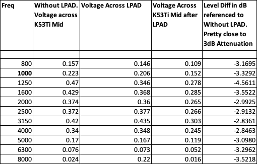
However, my LPAD for Mid section seems to measure well. Assuming 16 Ohms for K53Ti, for 3dB I used 4.7 ohm Series and 40 Ohm Parallel and here are measurements, Looks good enough as below measured: