


mboxler
-
Posts
574 -
Joined
-
Last visited
Content Type
Forums
Events
Gallery
Posts posted by mboxler
-
-
This is a continuation of a thread started in the Alerts section.
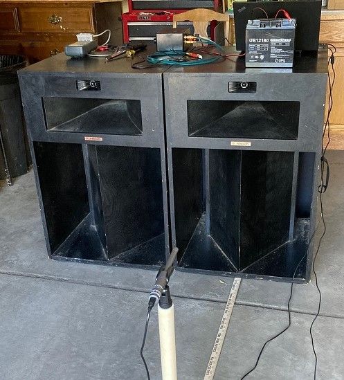
His La Scala's are currently stored in my garage, and I thought I'd post measurements. These appear to be completely original, except for what appears to be caked drywall dust everywhere.

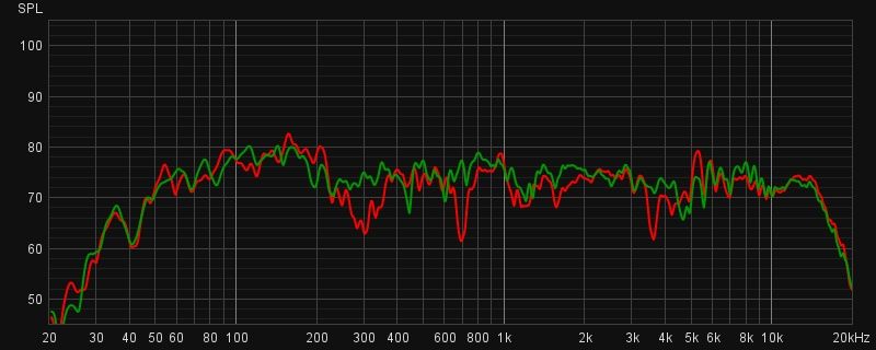
My first measurement was puzzling, as there were deep notches around 300hz, 700hz, and 3600hz (RED plot). Everything seemed to be wired correctly, but I decided to reverse the polarity of the woofer. I think that was the first time in 44 years that the spade connectors had been touched, as they were really stuck to the barrier strip.
The Green plot is with the woofer polarity reversed. To my surprise, all the dips vanished.
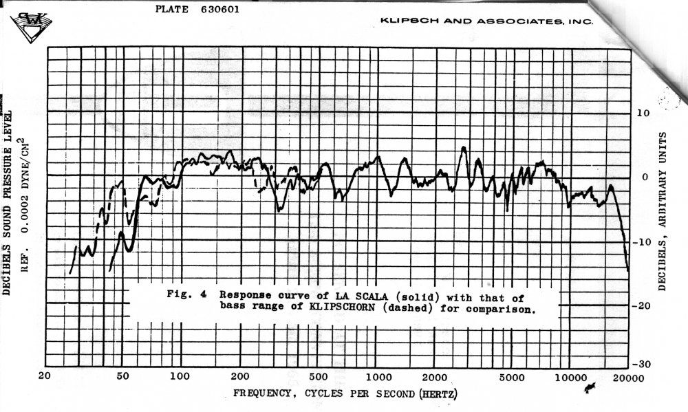
I did find an FR plot, and the RED plot does seem similar to the solid plot. Why the 3600hz dip vanished is even more puzzling. Thoughts?
I plan on measuring individual drivers next. I'll be out of town all day so these will have to wait. I also plan on checking the woofer itself to make sure it was wired properly.
Mike
-
 3
3
-
-
12 hours ago, archdukeobvious said:
I ended up getting them for asking price. Overall they weren't in too bad of shape, way better than my previous pair that came from a high school in the middle of nowhere.
@archdukeobvious texted me yesterday and asked if I'd tag along for the meet. I brought an amp and played some tunes to check them out, and gave him the thumbs up. I knew he needed a place to store them for a while so I offered my garage for a while.
These appear to be completely untouched. I'll be doing some tests, and we thought it would be a good idea to start a new thread with the results.
Mike
-
6
-
-
On 7/1/2023 at 9:38 AM, JMeader said:
My problem is a significant dip starting at 200 htz bottoming at 300 htz and gone by 400 htz
From the graph above any of the above "should" solve the problem
the 2.5 provides the widest coverage the others only extend to say 800 htz and then goes away.
Do you want to do the job and go away or provide an impact over the wider range
I truly appreciate your time in helping me understand this process.
Thanks again
Sorry...I missed your post. Took me a while to understand what you meant by "Do you want to do the job and go away or provide an impact over the wider range".
Ideally you want each driver to handle a specific frequency range. In the case of your La Scala's...
Woofer 20hz to 400hz.
Squawker 400hz to 6000hz
Tweeter 6000hz and above.
There will be overlap around the crossover points as the following plots will show.
I don't own La Scala's, so these plots are for demonstration only. The woofer simulations are courtesy of John Warren.
I plotted a couple of extremes. A 2.5mh alone and a 2.5mh with a 100uf shunt capacitor. The red plot (K55 response) is there to make my point.
Notice how the 100uf shunt capacitor boosts the SPL before it drops off? Without it the SPL is dropping off too soon before the K55 can take over. My thought is this may be causing the hole in your response. Without measurements, I can't say this is what is happening, but for a few dollars it would be easy to find out.

-
1
-
-
To give you an idea of what a shunt capacitor does, I ran some rough plots of the voltage across the woofer.
The green plot is a 2.5mh only.
The purple plot is with a 25uf capacitor.
The red is with a 50uf capacitor.
The blue is with a 75uf capacitor.
The "pink" is with a 100uf capacitor.
As you can see, the larger the capacitor, the more the voltage will increase, but the sooner the voltage will drop off.
Without a measurement, it will be hard to tell where you want the increased voltage.
Does that make sense?
Mike
-
 1
1
-
-
On 6/28/2023 at 9:36 AM, JMeader said:
I just did a full blown REW and then a DIRAC test and in my room the biggest issue we had was the 300htz dip.
Before you buy anything, can you run REW on each driver by itself? For the best results, you'll need an 8 ohm resistor across the tweeter output when measuring the squawker, and a 14-16 ohm resistor across the squawker output when measuring the tweeter.
That said, if you were to measure and post the woofer only response we might be able to determine the shunt capacitor value. I have a couple of 82uf capacitors I can send you if it looks like they might work.
Mike
-
1
-
-
21 minutes ago, babadono said:
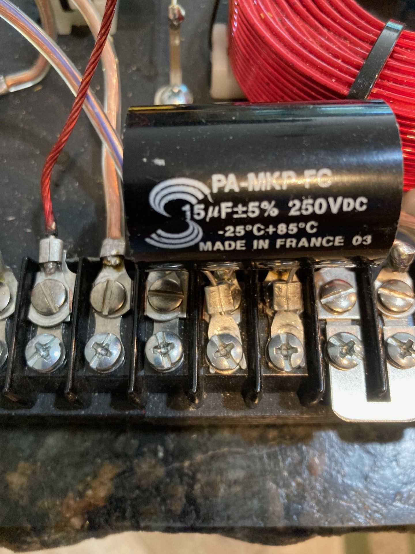
@mboxler your text says 50 but pic shows 15. Please clarify for anyone wanting to try. Thanks.
I happened to have a 15uf already crimped, so I used it for illustration. Sorry for the confusion. Different values will yield different results. I'd try anywhere from 33uf up to 68uf and see what measures/sounds best.
If you don't have spade connectors, just bend each end of the capacitor wire into a half circle, wrap it around the screw, and tighten. For testing I don't worry about the cosmetics 😎
Oh...non-polar electrolytic capacitors are fine here. They are also smaller and cheaper!
-
1 hour ago, JMeader said:
Mboxler
would this be at the driver connects or at the crossover connects
I am not electrical guy so if at the crossover does it have to be soldered ???
a photo showing install would be great
Thanks
It doesn't matter, but at the crossover terminals is easiest. I crimp the capacitor to a couple of spade connectors and attach them to the woofer output. I grabbed a 15uf already crimped and attached it. Hope this helps.
Mike
-
1
-
-
5 hours ago, JMeader said:
What have other done to counter this dip or do you just live with it.
If you have a 50uf or so capacitor place it across the woofer output terminals. This will extend the bass and may fill in the gap. You may need to reverse the polarity to the squawker and tweeter to compensate for the phase shift.
-
1
-
-
On 6/11/2023 at 11:51 PM, Edgeivi said:
...should I be looking at my solder joints on the crossover for a botched solder joint?
Yes. For example, if the last capacitor in the tweeter circuit is not properly connected, you will end up with a dead short around 7500hz.
-
1
-
-
34 minutes ago, winglet said:
Does that stock forte ii simulation include the 40ohm resister across the tweeter? I thought it was supposed to tame that hump.
Yes it does. I don't have a K75K so I used an 8 ohm resistor. That brings the load down to 6.6 ohms in my simulation. Again, this is a voltage simulation only.
-
14 hours ago, winglet said:
Stock forte II network has the crossovers at 650 and 7,000
Thanks. I couldn't find those anywhere. Without the acoustic measurements, I can only comment on the component values.
Al must have followed those points as well, as the first simulation shows.
The second plot is the stock crossover.
Mike
-
2 hours ago, attanasio666 said:
I'm talking about the Forté II ALK crossover design. It is different from his universal design. In the stock xover, the mid has inverted polarity but not in ALK's design.
I'm assuming you have followed the schematic on the first post. To make testing easier, I'd first move the tweeter circuit from after the 27uf capacitor to before it. I don't know why Al does that, but it does complicate things, at least in my simple mind.
I'm not sure why, but it appears to me that Al pushed the woofer to mid crossover from around 500hz to around 650hz. The mid to tweeter crossover was moved to 6500hz. I'd be curious if the mid can even get to 6000hz. Not sure if the woofer can get to 650hz either.
To be sure, I'd run plots of the individual drivers to verify my theories. I know it's a pain, but the good news is you can leave the back off while measuring the mid and tweeter. If I'm right, I can suggest changes to the schematic.
Mike
-
1 hour ago, attanasio666 said:
Hello, I have some questions. I built this crossover network and did some other mods to the speaker. I kept one speaker stock. The modded one also has a Crites titanium tweeter and a tractrix horn for the tweeter. I measured both of them, outside, with the mic at 2 meters. As you'll see in the REW file I will share, there was some cancelation around the mid/woofer crossover point. I inverted the polarity of the mid driver and it got rid of that. The thing is, there is also some null all along the mid frequencies that weren't there with the stock components. These nulls seem to be pretty high Q so if you smooth the data, the nulls disappears so I don't know if they can really be heard. Still, does anybody have some explanation or can help?
Here's the link to the files: https://drive.google.com/drive/folders/17IMTjnHnIr2-0JBnd034awx8SE9JdlrU?usp=sharingEdit...when you say "this crossover network" are you talking about the Universal or ???
Before we chime in, does the crossover already have the mid polarity reversed at the autoformer so that when you "inverted the polarity of the mid driver" you ended up with no polarity change at all?
-
Hopefully the moderators will tolerate my "repurposing" of a T2A autoformer, 'cause here I go again...
If you have a T2A and want to get really close to a T4A, here's a hack you can try. The steps involved are...
Remove the common wire from squawker out negative.
Attach squawker out negative to Tap 2 of the T2A.
Add a 3.6mh inductor across Taps 2 and 5 of the T2A.
The winding ratio between taps 0 -5 and taps 2 - 5 happens to be 64.2%, or -3.85db, pretty close to -4db.
Mike
-
1
-
 1
1
-
-
2 hours ago, Deang said:
It has been over a month. I don't recall what @mboxlerfound with the T4A. I would be surprised if it's 4dB exactly. There is also a 5mH inductor in parallel with the driver, so I have no idea what the actual attenuation is.
I'm sure I have a T4A measurement somewhere, but I bet it's pretty close to -4db.
Granted all of the above will result in a 2nd order high pass to the squawker, but it's the ratio of the 13uf capacitance and the autoformer inductance that dictates how high in frequency the steeper slope extends. Also, if one defines attenuation as the voltage difference between the input taps used and the output taps used, the inductance really changes nothing. That doesn't mean the inductance doesn't change the transfer function.
Attached in the difference between a T4A (taps 3 -0) in parallel with a 5mh inductor and a T2A (taps 4 - 0) in parallel with a 5mh inductor.
The resulting inductance for the T4A is 3mh. The resulting inductance for the T2A is 4mh. Notice the steeper slope of the T4A. But more interesting, notice at 580hz that even though the T4A attenuates the voltage by an extra .65db, the voltage across the K55 is actually higher. As frequency increases, - .65db difference comes back into play.
If you were to use a 3.5mh parallel inductor with the T2A, the transfer function will be closer to the T4A/5mh combo, but the slight difference in the reflected impedance on the 13uf capacitor will change the curve some as well.
Mike
-
2
-
-
Another interesting point I'd like to make is the squawker attenuation. Even though the Type A squawker is on tap 4 (-3.3db), you'll notice the attenuation never gets above around -4.8db. This is due to the fact that two circuits are tied to the 13uf capacitor in parallel. As the tweeter load starts to drop, the load on the capacitor starts dropping as well. Eventually the value of the 13uf capacitor is too small for the parallel load and the voltage across the squawker stops increasing.
Oh well, I find it interesting.
-
2
-
-
1 hour ago, Klipschguy said:
The Type A network has the tweeter leg at “tap 5” but after the 13uf capacitor. I would assume the T2a would still provide some degree of the protection even though it seems the K77 is being run “wide open”?
Correct! Since the taps used on the A have more inductance, the slopes are not as steep and level off quicker.
The green and brown plots are the normal taps. The red and blue are when I moved the tweeter to tap4.
-
1
-
-
52 minutes ago, Klipschguy said:
Brilliant! Thanks for posted the plot, Mike.
If you don’t mind me asking, what if one took the E Network from “tap 3” to say “tap 2” in the tweeter leg, how would impact the roll off?
It may come as a surprise, but moving the tweeter from tap 3 to tap 2 has no affect on the squawker. Here's the new simulation.
-
1
-
-
55 minutes ago, Klipschguy said:
What effect does it have on the tweeter leg of the circuit (like the E Network)?
I don't think I have a REW voltage plot for this, but here's a simulation of the Type E network that may help. As you said, the squawker filter (green) is 10-12db per octave due to the inductance of the T2A. The tweeter filter (red) is actually third order (16-18db per slope) up to 400hz, the turns second order. It is kinda cool.
Mike
-
2
-
-
1 hour ago, Cooper60hz said:
Hi mike curious how you got 3mh for the first series inductor? Has anyone does built the es400 off the schematic in the manual?
Thank you
PM sent.
-
-
6 minutes ago, winglet said:
Yes. See what I wrote above
It's close to your original suggestion...
Oops. Missed that suggestion. @senzlez2 does this sound like something you're willing to try?
-
Would you guys agree that if he swapped the input and output wires the circuit will be easier to fix?
-
Actually, I now think both circuits might have been wired right to left. We were able to "fix" the woofer section but the tweeter section should probably be reversed. I'll draw out how to fix the tweeter circuit as is.

.png.0e2e3c070b64a2a9b4bcd25b37c153c9.png)
.png.2c1636192ff5705a2d96d486bc5e5e69.png)
.png.c8715bf1a173af585b86a47b33b3b559.png)
.png.4ea8a21a1059648a57f2cca27a55ed2e.png)
.png.7d5b71ada8847fbd19b6a5e3172334d6.png)
.png.2f8435677907bc149913fc1c544cdb9d.png)
.png.450eca916c0e031b0af5a468f41e81f5.png)
.png.0699ca07601b07b9b5b7d30a50015322.png)
.png.84aec9807468feef1e7578467c7d59ff.png)
.png.a8cb1f01baecc7905cb5c374e02e89e6.png)
"New" '78 La Scala's in the Garage
in Technical/Restorations
Posted
I wondered the same thing. Last night I placed a moving blanket on the floor and got the same results. Today I'm going to place a capacitor across the woofer output just see "see" what happens.
Your tab will be going up a little today 😎
I've always wanted to listen to La Scala's, and man they sound good. This is also the first time I can measure single phase plug K-55-V's. I did discover that one speaker was missing it's squawker gasket. Either it's always been missing or they are not as "untouched" as I had thought 😞