mboxler
-
Posts
580 -
Joined
-
Last visited
Recent Profile Visitors
6696 profile views
.thumb.JPG.e865cb9742a8f1a873e5b238842d7c3f.JPG)


mboxler's Achievements
Forum Veteran (4/9)
261
Reputation
-
Walk me through the wiring of a vintage Klipschorn
mboxler replied to RiotSqrl's topic in Technical/Restorations
That's what the Type A crossover is for. It's a passive filter. Your car stereo probably has active filters, but the result is the same. Send the voltage to the correct drivers based on frequency. -
Walk me through the wiring of a vintage Klipschorn
mboxler replied to RiotSqrl's topic in Technical/Restorations
Don't connect the speakers to the RCA jacks. Those are for your music sources. Connect the two wires in your hand to SPEAKERS (8Ω MIN). The posts on the receiver are push type. Simply push on the black or red tab, insert the bare part of the wire into the hole, then release the tab. Put the 1 wire into A R - (black tab), and the 2 wire into A R + (red tab). Both wires power the speaker. Turn the receiver all the way down. Verify the SPEAKER A is displayed on the front panel. Play some music and slowly turn the volume up. Make sense? Mike -
Just to put things into perspective... Move the amplifier cables from the woofer terminals to the tweeter terminals. Can you hear any difference? Regardless of the jumper used, it will come into play on only half of the circuit. It will have no affect on the circuit you plug the amp into. Regardless of the jumper used, or the amplifier connection, the first component the tweeter current will pass through is a $1 cement(?) 2ohm resistor. Perhaps swapping that out with a Mills resistor would better??? I'll stop there 😎 Mike
-
As I suggested in another thread, one can always move the tweeter circuit down a tap. In your case, move the tweeter circuit from Tap 3 to Tap 2. This will lower the voltage across the tweeter another 3db, and may tame the sibilance you hear.
-
Actually the E2 uses a 4mh woofer inductor compared to the 2.5mh inductor in the E. I did discover that reversing the phase on the squawker filled in a gap between the woofer and squawker. I don't recall the tweeter polarity making that much of a difference. I too play with driver polarity. The difference can be pleasant or not, but it's an easy change. Mike
-
LaScala equalizer or tweeter volume control question
mboxler replied to hugot's topic in 2-Channel Home Audio
If you can solder, you can try moving the tweeter circuit on your AA's from tap 5 to tap 4 (the squawker output tap). It will slightly raise the squawker output but the reduced K77 volume may work for you. It's a free mod and reversible. Mike -
The Heresy I and II used autoformers. Klipsch went to series resistors starting with the Heresy III. The crossover in your Heresy IV is pretty complex. Are you asking if autoformer(s) could be used in those?
-
Yes you do. One of the few things ALK stated that I agree with is that the K33 looks like a 1mh inductor with a DCR of 6 ohms @400hz. What equation are you using? Here's an LTSpice simulation of an AK-3 woofer low pass as well as a REW voltage plot. Mike

-
If you are referring to the electrical cutoff, it's closer to 350hz on an AK3 Klipschorn. I imagine it's still close to that on a La Scala, but I'll measure the impedance of a K33 mounted in a La Scala later today to be sure. Mike
-
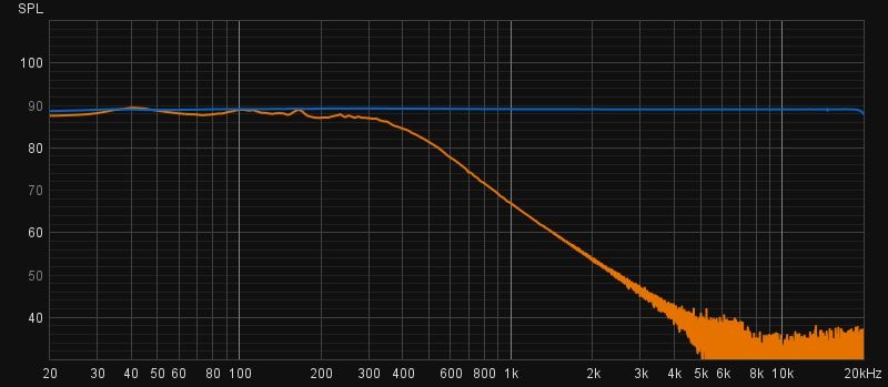
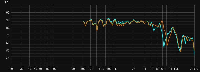
As is usually the case, the truth tends to be somewhere in the middle. To satisfy my curiosity, I ordered a pair of Altas PD-5VH's. Below are plots of a new PD-5VH (Blue) and an old K55V push pin (Orange). Both measurements start at 300hz on a K-400 horn with no filter. I'll let you decide the frequency responses of each driver. Again, the Altas driver is brand new. I don't know if the FR will change over time. Mike
-
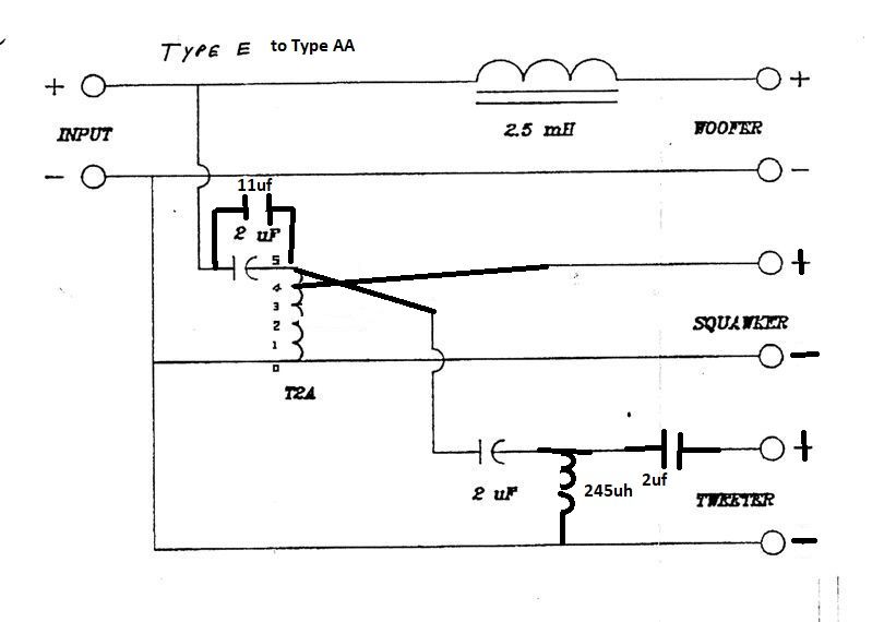
After all that drama, I forgot to answer the other part of your question... 1) Either add a 10uf to 12uf capacitor in parallel with the main high pass capacitor, or replace it with a 12uf to 14uf. 2) Move the K55V to tap 4 of the T2A. 3) Move the K77M to tap 5 of the T2A. 4) Change the K55V and K77M polarities back to normal. 5) On the tweeter filter, add a parallel 245uf inductor and second 2uf capacitor. Please excuse my poor illustration 😀
-
It may extend to 6khz, but not gracefully. Or am I missing something???
-
I may be a party of one, but I find the AA with those drivers unlistenable. To start with, the K55M's FR extends flat to 6khz compared to the K55V, which starts fluctuating around 4.5khz. I believe that's a big reason why the AL has the steep 6khz high pass to the K77M. The AA's tweeter filter is really closer to a 5khz high pass, and somewhat equalized to blend with the K55V. With the AA, there is an overlap from around 4.5khz to 6khz that I found annoying. I know this because I built a pair of AA's and tested them on my AK-2 Khorns. Again, I may be alone on this, but since you asked 😎 Mike
-
I assume you have the K55M and K77M? For my own information, does the K77M mount flush with the back or the front of the motor board?
-
The 4uf capacitor may be too small to work properly with this last change but as always let your ears be the judge.

.png.794fd6c18eaaf3199d737c2e049a5355.png)