


mboxler
-
Posts
574 -
Joined
-
Last visited
Content Type
Forums
Events
Gallery
Posts posted by mboxler
-
-
1 minute ago, babadono said:
If we could just do everything without wires

Where's Nikola Tesla when we really need him?
-
 1
1
-
-
@senzlez2, does the new layout make sense? As @wingletpointed out, the inductor was the biggest problem. The capacitor issue would have just made it sound different.
If my alphabet system works, I'll tag the tweeter circuit as I (we) see it should be just to be sure it's okay.
We all started out where you are. Don't be discouraged, it's a learning experience.
Mike
-
1 hour ago, Deang said:
Like Mike said, since the 3636 has exactly twice the inductance, the plots look symmetrical - but that does not mean they are the same. If you look closely, you'll see the rate of attenuation below frequency cutoff is different. Compare the capacitor only line, to tap 4 at 400Hz and 200Hz. 10dB/octave is not 12dB/octave. Since this relates to rate/amount of attenuation being applied just below frequency cut-off, maybe think about this in terms of what is happening at the diaphragm. It sounds different because it measures different. Now, there is a way to band aid this, and if you were paying attention, Mike discussed this in the AK thread.
Same with the capacitors. Modest change, but very audible - and of course all of these changes are accumulative in their effect.
Dean's right. The larger the inductance between the output taps to more the filter behaves like a first order vs a second order. Unfortunately, I can't remember if that test was with a new T2A or the way-out-of-spec one I removed from my Heresy. I'll rerun that voltage test with the Heresy one just to be sure.
-
15 minutes ago, winglet said:
On the + side, the 30uf cap input needs to be moved to after the 1.3uf inductor and then to ground. D to B, and B to the ground woofer out screw.
In your case, shouldn't he connect C to the ground woofer out screw?
-
27 minutes ago, winglet said:
Mike. Take another look at his very first picture of the crossover. If he removes the amp neg in connection to the 3.6mf inductor and instead connects it directly to the speaker out neg screw at the bottom, I think it fixes it.
That inductor is shorting the amp to ground
Explains the .4ohm reading he’s getting when he connects the multimeter to the speaker input terminals on the speaker with the installed new crossover
I agree, but I think there are other issues. Looks like the amplifier is directly connected to the 30uf capacitor. I'll try another approach. Hopefully clearer???
Connect Woofer IN- to Woofer OUT- (new black wire).
Connect Woofer IN+ to A (new red wire).
Connect B to Woofer OUT +.
Connect B to C.
Connect C to E.
Connect D to GROUND.
Connect F to G.
Connect H to I.
Connect J to GROUND.

-
1 minute ago, winglet said:
Oh holy hell.. now I need more coffee.. haha
Just don't let it go cold!
-
I'm very sorry. Once I rotated the picture things got clearer.
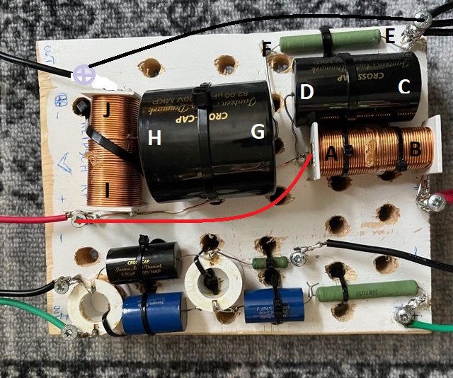
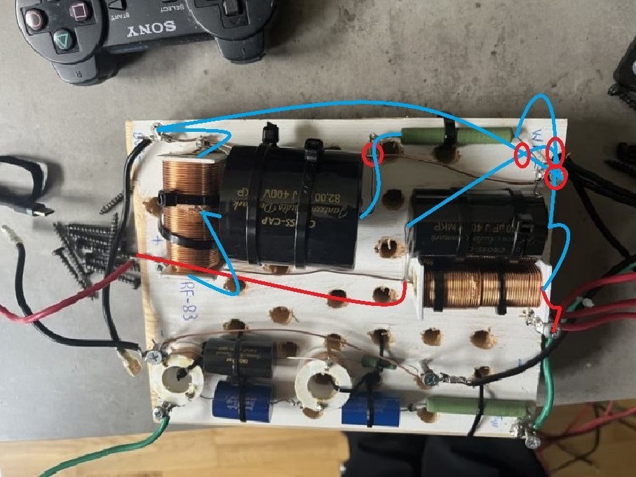
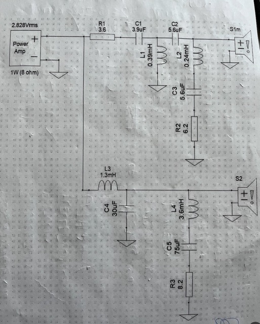
I've drawn how one way to wire the circuit. It follows the schematic in component order, although it could be wired other ways. I'll try to write out what needs to be done. Red is the positive path, Blue is the negative path. The red circles mean no connection.
Woofer in + to 1.3mh in.
1.3mh out to Woofer out + AND 30uh in AND 8.2 ohm resistor in.
30uh out to ground.
8.2 ohm resistor out to 75uf in.
75uf out to 3.6mh in.
3.6mh out to ground.
Does that look right @winglet? Still on my now cold first cup of coffee.
EDIT: I rotated the picture 90 degrees. Left is input right is output.

-
Rats! In my first post of this thread I said "I assume the bottom of the picture is input?". Is that not true? I'll rotate it and look again.
On my first cup of coffee, but I'll gradually wake up.
-
I see problems on the tweeter side. I have a feeling you don't measure an open circuit across the tweeter terminals with no straps? I'll try to draw how it should be. It may take a while. In the mean time, if you read around 4 ohms on the woofer terminals without the straps you should be able to hook your amp to just the woofer terminals and see how that circuit performs.
-
16 minutes ago, senzlez2 said:
0.0.4
something isn't right
My pair are set up for bi-wire, so I have the straps removed. I measure around 4 ohms on the woofer terminals and an open circuit on the tweeter terminals.
Sorry, but can you measure again with the straps removed?
-
3 minutes ago, senzlez2 said:
I have desoldered and bent the wire upwards its not touching the resistor, I tried to measure the ohm impedance again its the same, on both 0.0.4 on speaker terminals I have them all connected on the floor drivers and crossover , should it not be about 8ohm total impedance on terminals all connected together ?
8 ohms is a nominal figure measured with 20 to 20000hz sweeps. Your multimeter is sending and measuring DC, which won't work.
That's why you need to measure drivers disconnected from the crossover to measure the DCR of the voice coil. Once you apply AC everything changes.
I happen to have a pair of RF-83's. I'll check resistance at the terminals and get back to you. I'd still give it a try now that the resistor can do it's job.
-
With the 8.2 ohm resistor "bypassed", the impedance of the woofer circuit drops to a dead short around 300hz. That's the resonance frequency of the 3.6mh in series with the 75uf capacitor.
-
5 minutes ago, senzlez2 said:
yes it does its one of the ground cables you pointed out I put on
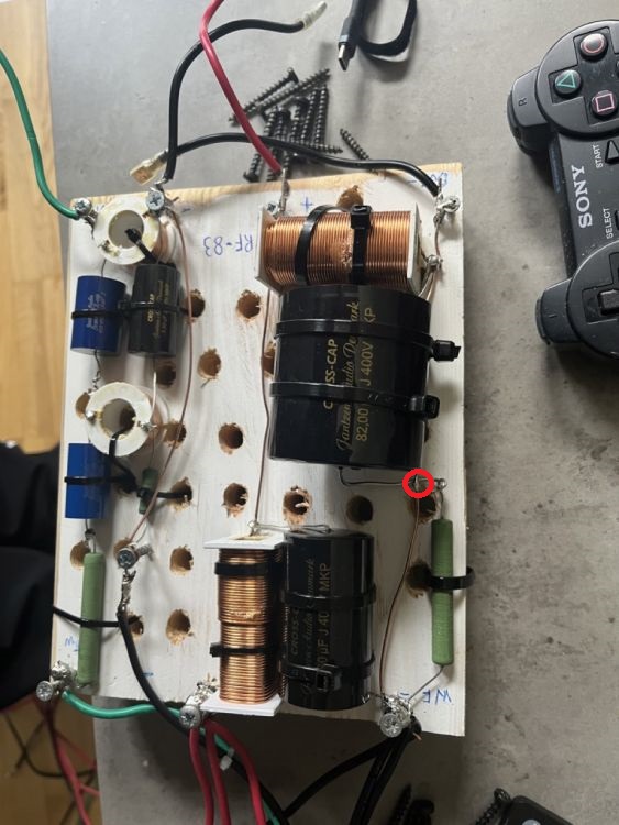
Sorry, I meant a wire from the bottom - to the top - with no other added connections. That resistor is already connected to the bottom -. You've shorted out the resistor with that joint. Try desoldering that spot and bend the wire over that "intersection" to see if that fixes the issue. Later I'd clean that up.
-
1 minute ago, senzlez2 said:
yes it is
You don't want a connection there. Can I assume that wire then goes to the - terminal at the top of the picture?
-
17 minutes ago, senzlez2 said:
ok I have measured all the drivers from both speakers , all measure about the same so its nothing to do with the drivers, is there polarity on the coils? there is no polarity on the caps and resistors I used, can someone go over the crossover I built it should be right, im at wits end, maybe I should have just bought a second hand crossover
Is this a solder joint (red circle)?
-
What ohm reading do you get on the drivers in the speaker with the new crossover?
-
16 minutes ago, Deang said:
The curve for the 3636 did not look like 12dB/octave to me.
I agree, kinda. When I run the simulation with the 3636, the slope is 12db/octave up to about 100hz, at which point the slope starts to flatten out. The steeper slope is there, it's just useless. With a T2A, that slope will extend much further into the audible range.
-
 1
1
-
-
39 minutes ago, senzlez2 said:
I have only 1 speaker hooked up to my amp with new crossover,
On the speaker with the new crossover, disconnect the speakers from the crossover and measure the DCR from the + wire through the tweeter to the - wire.
Do the same with the woofer(s). Hopefully there isn't a short of some kind.
-
As already stated, the two biggest differences between the T2A and the others is the inductance and the -3.35db tap. Of the two, I believe the inductance has the biggest effect. Of course, the combination of a "brighter" polypropylene capacitor combined with .35db less attenuation might be noticeable as well.
Even though all of the autoformers will result in a 2nd order high pass to the squawker, the inductance between taps 0 - 4 dictates how high in frequency the 12db slope extends. The lower the inductance, the higher in frequency the 12db slope extends.
I can't find any published specs on the 3636, but one of them I have measures around 90mh between taps 0 - 5. The published inductance of the T2A is 45.6mh +/- 15%. A T2A I removed from an old Heresy measures 32mh. Since the inductance between taps 0 - 4 forms the second order, the values are...
3636 45mh
T2A (spec) 21.2mh
T2A from my Heresy 15mhAlthough my T2A may be an extreme case, you can imagine the difference the shunt inductance would make.
Mike
-
 2
2
-
-
5 minutes ago, senzlez2 said:
hello again, I has attached ground on tweeter and bass section, its still cutting out when pushing the volume, maybe I have changed the impedance of the whole speaker ? im using a Yamaha a-s1200
Hmmm. Can you post another picture of the new crossover?
Also, it might be a good idea to measure the DCR of the voice coils on all your drivers. Perhaps whatever damaged your crossovers also damaged a driver.
-
Tap 4 on a T2A is -3.35db vs -3db on the others.
-
When I simulate the circuit the way I think it is now, the impedance drops below 2 ohms around 1khz. Then it sharply increases to 50 ohms at 2khz. That's a tough load on an amplifier.
-
44 minutes ago, senzlez2 said:
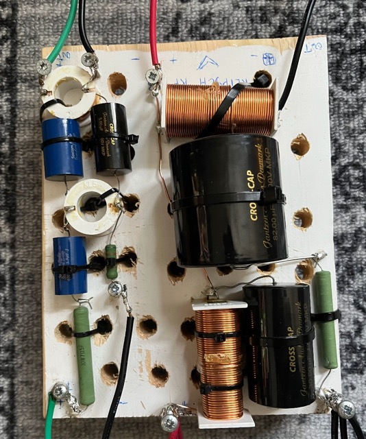
hello I built a new crossover for my Klipsch rf-83 my old crossovers was burnt on 2 of the boards, I just need to double check if this is right, probably not.
its coming sound out and the speaker lacking a little in bass, but when I push the volume up the amp cuts out, I followed this crossover schematic I just used the leads of the caps and resistors and. coils mostly, it doesn't look pretty I used the stock coils from the bad crossover boards, regards
Looks to me you are missing a common ground wire on each circuit. I assume the bottom of the picture is input? If you run another black wire from the bottom right screw to the top right inductor (where the other black wire is connected) the woofer circuit should work.
Likewise on the tweeter circuit.
Unless you connected them underneath the board???
Mike
-
1
-
-
What DC reading did you get? Sounds like you need a larger capacitor.
help with new made Klipsch RF-83 crossover build, amp cutting out when volume is increased
in Technical/Restorations
Posted
Okay...now I'm confused again. In my last picture the words OUT are on the left side, but there are three wires on the right side that I assumed were to connect to the three woofers.
Which is it????