ninjai18
-
Posts
231 -
Joined
-
Last visited
Content Type
Forums
Events
Gallery
Everything posted by ninjai18
-
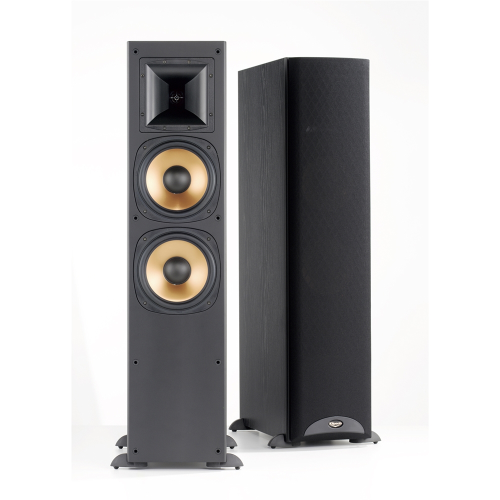
Newbie looking to upgrade crossovers on my Reference RF-3 ii
ninjai18 replied to ninjai18's topic in Technical/Restorations
Posted on parts express forums asking for help on wiring it up on a new board and the 4th post answered my question perfectly. Also posted the question on diyaudio and got very timely and friendly responses. Amazing all the nonsense, insults, and lectures I had to wade through on here to get any kind of answer. Sad, really. -
Newbie looking to upgrade crossovers on my Reference RF-3 ii
ninjai18 replied to ninjai18's topic in Technical/Restorations
The best thing you can do at this point is order a replacement pair of crossovers from Bob. This will instantly get your speakers up and running. While you're waiting, supply Dean with all the information he's requested regarding your gear. He'll let you know what to purchase. Start practicing soldering. Once you're competent, use Bob's crossovers as a template as to what yours should look like as Bobs will come mounted on a board similar to what you're thinking about doing. This way your speakers will be up and running, you'll have honed your soldering skills and you'll see how to wire your crossovers correctly as you'll have a properly wired example to follow without having to learn how to read a schematic.I've already inquired with Bob about it in the past, it's just way too expensive. I just want to try my hand at wiring up the components on a piece of wood. I did blow one cap but I have a replacement. (also, I confirmed the circuit board is dead) I did some testing, I'm certain that's what it is. I'll try to figure out the wiring on my own. Everyone seems keen on lecturing me as if I was their 10 year old son working on a pinewood derby car. Thought this place would be a lot more helpful, oh well. Thanks to those that actually helped, minus the lectures. I'm out. -
Custom Senergy F-3 enclosures and crossovers...
ninjai18 replied to BACKPORCH's topic in Technical/Restorations
Don't dare ask for help and mess anything up by accident. You'll get a bunch of elitist pricks jumping down your throat about it. -
Newbie looking to upgrade crossovers on my Reference RF-3 ii
ninjai18 replied to ninjai18's topic in Technical/Restorations
Enough with the damn lectures man! Why on earth would you "be on the hook"? This is a forum correspondence, I'm not paying for information, thus I would never "blame" you for anything I messed up. I am not blaming anyone for anything, I am asking for assistance in wiring things up. Seriously, you are getting really annoying now. F**k off with the damn lectures, dad. Good god. Didn't know this forum was so full of lecturing a-holes ready to throw any mistakes you make on a project in your face. F**k me. -
Newbie looking to upgrade crossovers on my Reference RF-3 ii
ninjai18 replied to ninjai18's topic in Technical/Restorations
Why don't some of you just say you don't want to help instead of telling me how unskilled I am and throwing around "I told ya so" remarks? Seriously, no one is forcing you to help. Enough with the rude elitism. If you want to help me learn how all this works, great. If not, than please excuse yourself from the discussion. I did follow the advise given but obviously made a mistake in the process, it happens. Get over it, jeez. I never once said I was a pro or didn't need help, that's why I'm asking! Why do you guys think it's such a big deal for me to ask for step by step instructions? I have looked around online and can't seem to find a step by step guide for a crossover similar to this one. I wasn't aware this was a forum on "parenting" novices who are asking for help.. It's a shame, because this thread could really help other people who have RF-3's that are new to this but could do it with a step by step guide. Guess that's too much to ask.. (funny, because I sware I've seen plenty of other posts guiding newbies through other projects) -
Newbie looking to upgrade crossovers on my Reference RF-3 ii
ninjai18 replied to ninjai18's topic in Technical/Restorations
Thanks man, I appreciate the kind words. I really need my fellow Klipsch fanatics to help me here! I am without speaker, i'm dyin here, I need my speakers man! On the plus side, once I have them all wired back up, they will sound better than ever from being without them for so long. -
Newbie looking to upgrade crossovers on my Reference RF-3 ii
ninjai18 replied to ninjai18's topic in Technical/Restorations
I honestly don't think it is. There's stuff you can't see in the pictures. Would you mind helping me through how to connect the parts up on a piece of wood? That is the route I really want to go now. I don't have the time to wait in line to have them done for me. I also don't have old crossovers to work on. I'd like to learned how to wire them up on a piece of pine board, it sounds really fun and doesn't look too hard. I just need to know what connects to what. -
Newbie looking to upgrade crossovers on my Reference RF-3 ii
ninjai18 replied to ninjai18's topic in Technical/Restorations
I thought I was but I'll share the love. How about we cool it with tearing me apart about it? Just take a chill pill guys. It's not like I messed up your personal speakers. You don't want to help? Fine. But I don't need lectures. I was aware of the risk going in. I appreciate the help, but please cool it with that. -
Newbie looking to upgrade crossovers on my Reference RF-3 ii
ninjai18 replied to ninjai18's topic in Technical/Restorations
Okay, so I do believe the PCB is messed up beyond my skills to repair. I took all the crossover components off the board and have decided to put all parts on a little wood board with hot melt glue. I just need to know how to wire the compenents up to one another, how to wire the woofers and tweeters to the crossover, and how to wire the crossover to the speaker + - terminals. I figure it's a good time to learn how to do this anyway, it'll be fun!
-
Newbie looking to upgrade crossovers on my Reference RF-3 ii
ninjai18 replied to ninjai18's topic in Technical/Restorations
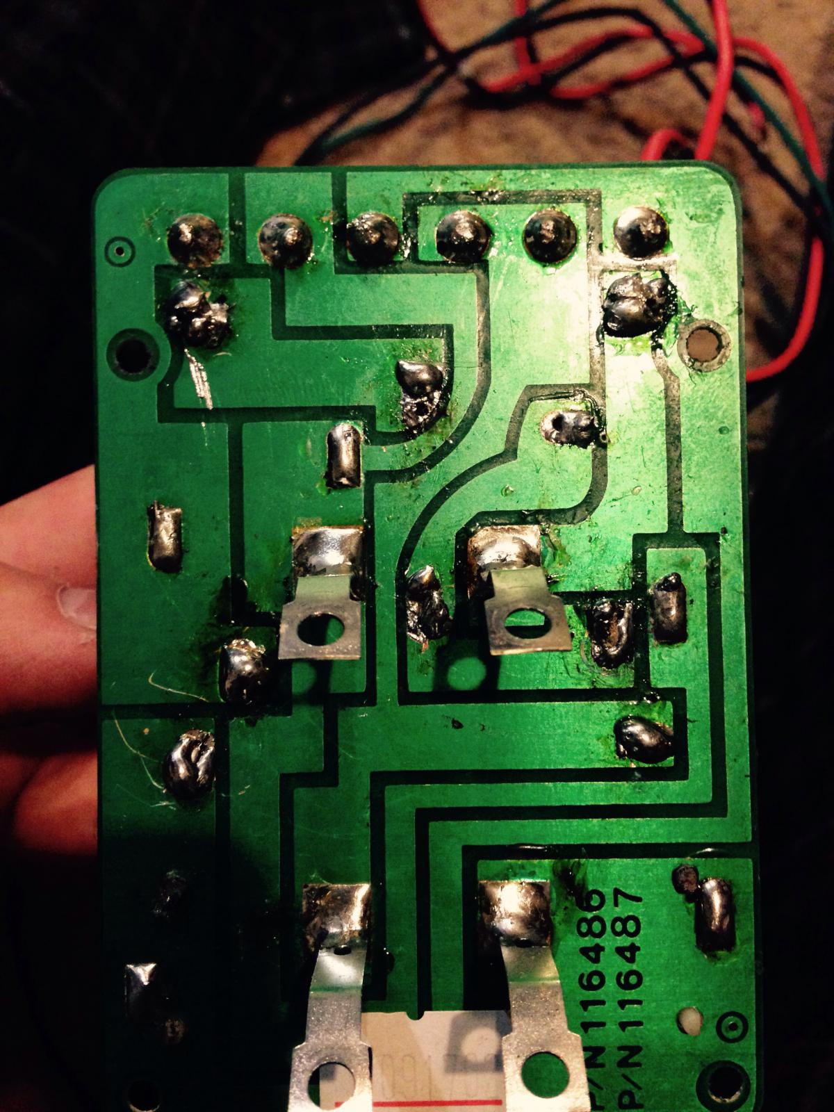
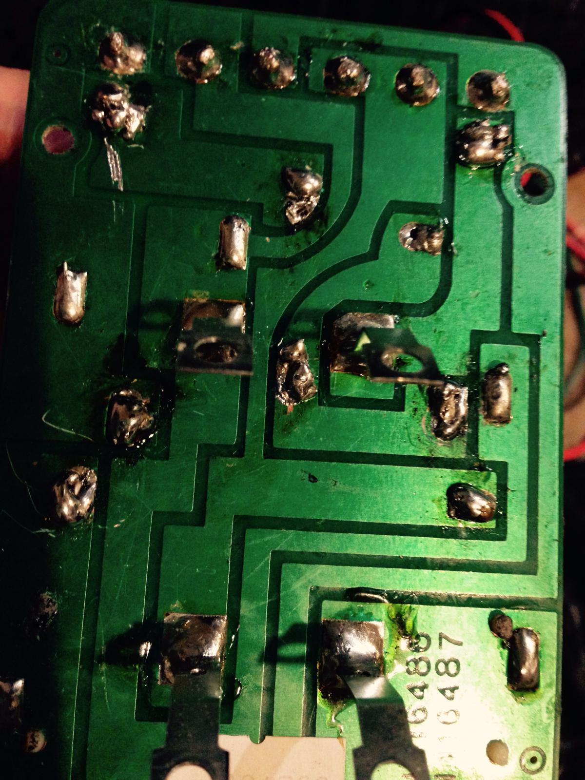
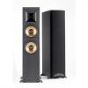
Okay, here's a few pictures I took. A little piece of the green PCB board started to come up when I removed the solder on the 12uf cap. It also did take a while to melt down the solder. Hey cranky, how much would it cost me to send you all five crossovers, and the upgraded parts I bought, for you to do the soldering work? P.S. You guys were indeed correct, you all saw this coming.
-
Newbie looking to upgrade crossovers on my Reference RF-3 ii
ninjai18 replied to ninjai18's topic in Technical/Restorations
I'll get some pictures today. What would cause a cap to short? -
Newbie looking to upgrade crossovers on my Reference RF-3 ii
ninjai18 replied to ninjai18's topic in Technical/Restorations
I'm gonna take some high res photos and upload them, maybe someone can provide insight as to what I did wrong. Would I still get good sound if I put the crossover network on a wood board, but orient everything as close as possible to how Klipsch had it originally on the PCB? Also, if the new solder is touching a trace, could that be the problem? -
Newbie looking to upgrade crossovers on my Reference RF-3 ii
ninjai18 replied to ninjai18's topic in Technical/Restorations
I think I burnt the PCB accidentally. I'd like to just wire everything up on a little piece of wood and glue it inside the cabinet. Any good guides on wiring up a crossover network without a PCB circuit board? -
Newbie looking to upgrade crossovers on my Reference RF-3 ii
ninjai18 replied to ninjai18's topic in Technical/Restorations
Did the upgrade to one of my towers and now I have no sound coming from the horn... :/ Woofers work, but no tweeter. -
Newbie looking to upgrade crossovers on my Reference RF-3 ii
ninjai18 replied to ninjai18's topic in Technical/Restorations
Parts will be here this Friday, I'll keep you all posted on my progress! -
Newbie looking to upgrade crossovers on my Reference RF-3 ii
ninjai18 replied to ninjai18's topic in Technical/Restorations
Anyone have a super cheap old soldering iron they could sell me with a little solder? -
Newbie looking to upgrade crossovers on my Reference RF-3 ii
ninjai18 replied to ninjai18's topic in Technical/Restorations
You have high jacked my thread, but you guys are awesome, so all is forgiven! -
Newbie looking to upgrade crossovers on my Reference RF-3 ii
ninjai18 replied to ninjai18's topic in Technical/Restorations
Ordered parts, can't effin wait!! -
Newbie looking to upgrade crossovers on my Reference RF-3 ii
ninjai18 replied to ninjai18's topic in Technical/Restorations
Dean, I wasn't implying you weren't being helpful, I didn't intend to come across that way and I apologize if I did. :/ You really have been incredibly helpful. You said no electrolytics or polyesters, so the metalized polypropylene..? -
Newbie looking to upgrade crossovers on my Reference RF-3 ii
ninjai18 replied to ninjai18's topic in Technical/Restorations
Will do. The Bennic have a 10% tolerance, isn't that too high? Dean did recommend the Bennic caps earlier in the thread though, so this confuses me...EDIT: I think I was looking at the lower quality Bennics, I found the 12uF 5% purity ones. Much more expensive. Okay I found the 1% tolerance caps. I am wondering, would there be a noticeable difference between the more expensive 1% purity caps and the 5% purity caps? -
Newbie looking to upgrade crossovers on my Reference RF-3 ii
ninjai18 replied to ninjai18's topic in Technical/Restorations
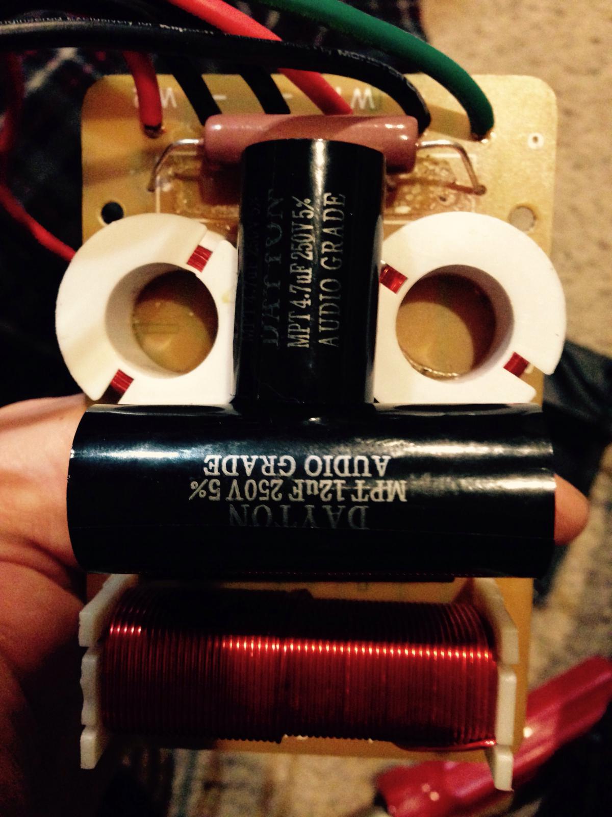
It actually says 18.0J 100V on the big black one.. Do I need to replace 3 caps per speaker? There are two orange caps and one large black one. The Bennic caps are more in my price range. Would those still work and sound good? -
Newbie looking to upgrade crossovers on my Reference RF-3 ii
ninjai18 replied to ninjai18's topic in Technical/Restorations
Replace part for part value...The RF-3 schematic shows a 12 and 4.5 mFD on each crossover (plus the larger 18, which is across the woofers). This would mean you would need: 2 x 12mFD 2 x 4.5mFD 2 x 2 ohm Mills non inductive resistor. Look at the value written on yours to see if the smaller ones are 4.5 or 5. Gotcha! That makes perfect sense. So you do recommend replacing the large black one? -
Newbie looking to upgrade crossovers on my Reference RF-3 ii
ninjai18 replied to ninjai18's topic in Technical/Restorations
You are catching on Yes, that would work. I knew it was a matter of time before I did. How many caps per speaker do you recon I'll need? Will each speaker need two different caps or just two of the same? (Plus the resistor) Am I correct in my understanding that I don't need to replace the large black capacitor, but the one underneath it and the one in front of it? -
Newbie looking to upgrade crossovers on my Reference RF-3 ii
ninjai18 replied to ninjai18's topic in Technical/Restorations
So I noticed there are no Mills resistors that are 2 ohm 10 watts, but there is one that is 2 omh 12 watts, would this still work? -
Newbie looking to upgrade crossovers on my Reference RF-3 ii
ninjai18 replied to ninjai18's topic in Technical/Restorations
If you think the schematic is correct, REPLACE with the same value as what is already there, i.e., if there is a 10 watt, 2 ohm, 5%, replace with the same.The caps should be non polarized and follow the same thing. A 12 microfarad, 100v rating. If you change the capacitance value of the caps, you will change the crossover point. The voltage rating can be higher, but the part will be physically larger, same with the resistor. This will make it harder to place on the printed circuit board. As Dean said, the Dayton caps and Mills, non inductive resistors will be better than what is there now. Bruce Awesome, this is super helpful! It's starting to click. I noticed many capacitors on parts express do not say if they are polarized or not... I noticed Dean also recommends using Audyn caps, which do you think would be better, Audyn or Dayton? I have also seen Bennic suggested. He said to replace the Orange-ish oval shaped caps, are the two orange caps the same? I don't notice any markings on them that differentiate them..