


ToolShedAmps
-
Posts
207 -
Joined
Content Type
Forums
Events
Gallery
Posts posted by ToolShedAmps
-
-
I just wanted to know how he found the forum. If you google "toolshed audio" this thread doesn't come up, I haven't looked past 5 pages of results fwiw.
Most of my customers follow me on Instagram and Facebook. I had mentioned that I was going to publish a Line-Stage "build-thread" on this forum if anyone had any interest they were invited to join the forum.
Matt.
BTW, some of these "follower/customers" might be interested to find out how GOOD Klipsch speakers are, so I'd be a little less aggressive with the newcomers.
-
What a roller coaster ride this thread has been! I just read through it and was amazed at the twists and turns it took!
Matt was so great to work with through this project. I'm so thrilled with the outcome, the sound is exactly what I was looking for, it looks the way I want it to look - and works great with my Zu Soul Supreme speakers. I love the sound of the Zu's, but they have some quirks that make them a challenge with single-ended tube amps previously. I knew the Zu's could produce solid bass, but I just wasn't getting it from my previous amp. I've told Matt that the Transcendence 12 sounds "authoritative" a couple times, because it's the only way I know how to describe it. I listen to a lot of Americana music that isn't too demanding, but I do like it loud when the source music calls for it. My pass/fail test was a Lucinda Williams track (newest CD: Down Where The Spirit Meets the Bone) that had some bass that the Inspire KT-150 could not cleanly reproduce. My T-12 does it in spades.
Anyhoo - just wanted to send out a thanks to Matt for being a pleasure to work with and accommodating my OCD in certain design elements of my amp! I have so much more time on my hands now because I'm not constantly searching Audiogon for a tube amp that I think might work with the Zu's. I've found one. Search is over. The only downside is that I'm not getting as much sleep as I used to, because I end up listening to music later into the night than I was previously...

First post and you don't have Klipsch speakers. Are you friend or family to toolshed amps? How did you find this thread?
Wow, just when I thought you were going to be decent....
If it wasn't ABUNDANTLY clear, this guy is a "CUSTOMER"..... not a relative, not a "high-school" buddy.....kapisch?
-
Thanks Mike!
Can't wait till Elrog comes out with a 45.
Matt.
-
You know what is funny about this? It is NEARLY the Genesis6
Well you know Matt I guess great minds do think alike
They sure do
-
Here is another option, instead of dual triodes where one triode is going to be wasted use a noval pentode. Sensitivity is greatly improved so there is no need for a preamp and THD is down to 1.8% at full output. Spectrum looks a little better too. It shouldn't be too hard to build it one way and listen for a while and then change it later on.
You know what is funny about this? It is NEARLY the Genesis6
-
Matt-
Also, one more grounding question for you. Since the chassis is now anodized inside and out (NO longer electrically conductive), does this change your grounding advice at all? Just curious. Thanks!
-Corey
Corey,
At the three grounding points on the inside of the chassis it probably wouldn't hurt to sand or scrape away a bit of the anodizing to get to the raw aluminum underneath. Aluminum is a pretty good conductor so your ground plane should be sufficient.
Matt.
-
I agree, however, since we were starting with a dual-triode, I selected the one that I found to perform best as a driver within this context in a noval envelope. There are a few triodes that offer excellent linearity and transconductance but aside from the almost "un-obtainable" 5842/417a, they all have some sort of weird filament voltage that would make it difficult to implement considering Corey already has his tranny's and chassis. AND, for whatever reason, the "hearing" test does not concur with your sim findings even running the source direct without a line-stage adding anything to the signal. Obviously, I prefer the pentodes I listed as more optimal drivers in this config., but, wiring them as "pentodes" requires an additional load resistor and coupling cap tied to ground to power G2 at the correct voltage, in this config., G3 is tied to ground or alternatively, the cathode.
Matt.
-
Hey Matt, feel free to look over my schematic maybe I made some errors. I will have to dig out the article and look at the math for inverse voltage feedback but I think it only cancels 2H so if the circuit has higher order harmonics they will now dominate.
Now plug in a 51v zener, bypass with a 0.01uF cap in place of the 2.2K G2 resistor, replace the cathode resistor with an LM317 set with a 27R resistor (@40mA) and leave the 100uF bypass cap in there. Has plot changed?
Thanks.
-
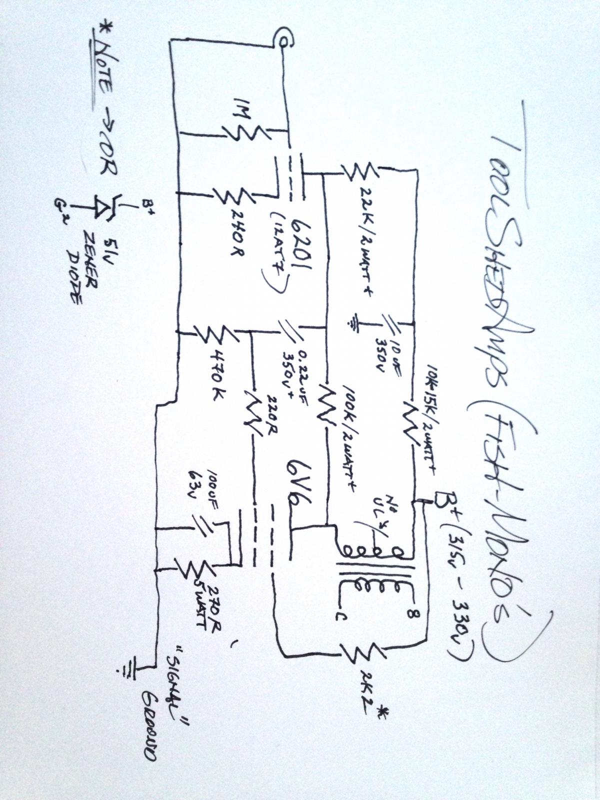
Hi JPM, are you sure you have my feedback loop plugged into your sim correctly? The 12AT7 (actually I prefer the 6201 or 5965) is an EXCELLENT driver in this design. This is the circuit I built for most of my kids and friends. In my opinion, the only driver that can eclipse this performance is another pentode. Either the 6AU6, D3a, or E80F, none of which can be simplified enough for "Corey" to just plug into the circuit and go. FWIW, I use a variation of THIS driver topology in my Renaissance4, tweaked to drive the EL84.
Corey will be MUCHO HAPPY with this design.
Matt.
-
OK, I thought I would just double check the ORIGINAL PS parameters and guess what? The author may not have verified the values of components prior to publishing it. As it sits, (although I don't know the resistance of the HT winding of this particular PT) I am calculating a B+ of LESS THAN 300v.
Can either JPM or Maynard check it as well? Also, it seems that the rise-time could be improved as well.
Matt.
-
Thanks JPM, those are great ideas.
6V6's sound GREAT at the above mentioned plate and screen dissipation levels, however, should you want some longevity out of the power tubes, I would recommend reworking your existing PS schematic to drop B+ to about 305v (which is the "sweet spot" for this design).
Don't change the value of the feedback resistor (per my schematic), it is actually 1.71v to full output (factoring in the supply voltage @ 305v), but, sounds FANTASTIC. An active line-stage would be appropriate (like the one started in the new thread.
On the other hand, any source capable of 1.71v can drive the amp to full power anyway.Matt.
-
Hey thanks a bunch guys. I'll skip the triode switch then. Matt, I really really appreciate your help. I noticed you eliminated the volume pot from the circuit. Not a huge deal since I have a buffer as my volume control but I thought it might be nice to leave in for channel matching? I'd love to hear your take. If I do, I assume I can just shove it in there? I'll look at the two schematics and figure out what I have already and what I would need to buy to make the proposed changes. I have no doubt it'd be worth it. Maynard, Joe, and wdecho, thanks for your input as well. I'll keep ya'll updated.
Sent from my iPhone using Tapatalk
Ok then, there ARE a couple of things I'd like to point out with the design I sent you.
1) YES, please add a 100K Mono pot between the input and the grid of the 6201, this will function as an input gain/balance control for each mono.
2) Wire the 6201's using the "opposite" triode in each bottle (Pins 1,2,3 on one amp and 6,7,8 on the other amp), this way when the tubes get near the end of their usable life, you can just swap them for each other to have a "fresh" pair of new drivers.
Lastly, 3) A bit about "grounding" the amp. Do the following: Ground the IEC directly to it's own point on the chassis, do not use the filament center-tap (cut it off and shrink-wrap the end) then tie a cement 100 Ohm 5 watt resistor to each leg of the filament and land them on the same ground point as the IEC ground. DO NOT GROUND ANYTHING ELSE TO THIS POINT. This is the "Chassis or Earth" ground.
Next, tie ONLY the following: HT center-tap, C8, C9, C10 and the "Bleed-Down" resistor R15 (per your PS schematic) to a separate ground point on the chassis. This is the "Power Supply" ground. NOTE: The 10uF smoothing cap ground will become part of the "Signal" ground which contains the rest of the grounds per the circuit INCLUDING the input jack ground. My recommendation is to run a separate "Flying Lead" from each "group". This group should have it's own tie-point (either a turret or lug) from which to solder the flying lead. Group or "Node" 1) 100K Pot, 6201 grid-leak and cathode, Node 2) 470K grid leak, Node3) 100uF by-pass and cathode of 6V6. These 3 Nodes, along with the Input jack flying lead should be "SOLDERED" to a copper ground lug (after they are appropriately "squished" down/secured with the set screw) then attached to the chassis at third location.
Note: As I am truly "anal" about sympathetic mechanical vibration, I always use fairly soft durometer rubber washers between the PT, PS Chokes, and OT's and the Chassis, I never use the PT bolts as ground points. I drill separate holes in the chassis for that purpose.
Cheers!
Matt.
-
I totally agree with Maynard on his suggestions regarding the original schematic. If for whatever reason you "need" to build that amplifier, I would suggest doing away with the triode "strapping" idea through a switch/or not altogether as I have performed many "blind" listening tests with the 6V6 wired Triode and Pentode and could never justify the drop in power output for this particular tube. On the other hand, if you are going to build either this schematic or the one I attached, AND, you really would like to use the ultralinear tap, I would recommend dropping the voltage from the tap "through" a 21v/3watt Zener "bypassed" with a 0.01uf/350v film cap. This will ensure you keep the potential of G2 below that of the plate.
Matt.
-
-
I've never been a big fan of "global feedback" let me scribble something up for you that will sound much better. Since you already have your cool purple anodized chassis drilled I won't mess with the number of tubes required, just the choice of driver. Matt.
-
Hey all. I'm somewhat new here. Ive built a few kit projects, most recently a decware zen kit which I really like.
Anyway, I just finished Ed Jurich's book and I am in the middle of building the 6v6 single ended amp found here
http://www.ejjamps.com/articles/6V6SE-6L6GC-amplifier-circuits.html
The only mod I am doing is putting in a heater switch so I can run 6cg7 in addition to 12au7/12bh7
My question is whether it is worth putting in a triode mode switch so I can run the 6v6 in triode mode. If you guys think it would be worth it (I don't need more than 1-2wpc with my speaks), would someone be willing to draw it for me quick? I'm a rookie. Thanks folks!
Corey
Sent from my iPhone using Tapatalk
Hi Corey,
How far along on the build are you?
Matt.
-
Thank you again Fjd, William and Maynard.
I, like Maynard, have spent countless hours subjecting my family and friends to "blind" listening tests for a very long time. As Maynard pointed out, you cannot "hear" a difference in the "aesthetic" quality of a binding post. From a purely "engineering" perspective, I will not use a conductor made from a "sub-optimal" material, such as steel in place of copper (irrespective of the fact that the electrons flow on the "outside" of said conductor). Secondarily, "form" will NEVER follow "function" in any of my designs.
On the other hand, you CAN hear the difference between an $18 Edcor Output Transformer and the very expensive OEM TAMURA Output Transformers in the Genesis6. Likewise, differences can be heard in coupling capacitors, by-pass capacitors, loading resistors, etc. I believe these "differences" to be the point at which science meets art.
The goal of any designer is to "leverage" budget for the best possible outcome irrespective of what the actual budget may be. In the pre-amplifier build thread, I will address this "leveraging" to a greater degree to help DIY'ers better understand what I happen to think makes a difference regarding component selection and how it impacts the "sound" of the finished piece.
Cheers!
Matt.
-
-
Thank you Kirk.
I'd have thought better of a moderator. The guy calls me a "Troll" and you thank him.
I think I may be done here.
I thanked him for that compliment he paid me, nothing more. To me the trolls comment was not directed at you (after rereading it, I can certainly see how you could interpret it that way). I realize you're new here and really don't know me but I would appreciate the benefit of the doubt until you do. I'm human and miss things from time to time but I do have a low tolerance for trolling and condescension.
Thank you for responding Carl, I apologize for not affording you the benefit of the doubt.
Matt.
-
Ah, now that we are at the point at which a member whom hasn't been part of this "hoopla" has been gracious enough to point out what has actually transpired on this thread (thank you Fjd), I think we can move beyond this. "Water under the bridge" so they say.
Let me be clear, healthy discussion is good (even agreeing to disagree), however, condescending attitudes and/or remarks, abrasive comments, and other attacks that undermine or debase me or my product I simply will not tolerate. I am here (on this forum) to help others who enjoy Klipsch speakers as much (perhaps more) than I do. I believe I have a wealth of knowledge and experience that will help the less informed members of this forum. Additionally, I am beyond the need to "prove myself, or my amplifiers" to anyone. I have just offered the forum (and ANY DIY'er on the planet) one of MY pre-amplifer designs "FREE". And, to my knowledge, the ONLY current-production design ever offered by anyone who is trying to earn a living doing this. That said, I PROMISE to help when I can, and do so in a manner that isn't aggressive, accusatory or condescending. I welcome the opportunity to educate and converse in an environment that is welcoming and beneficial to all.
I hope we can all pledge the same thing.
Matt.
-
Thank you Kirk.
I'd have thought better of a moderator. The guy calls me a "Troll" and you thank him.
I think I may be done here.
-
Matt,
The Pioneer dual-sub says it in 8 ohm on the label (see picture). Though is says "8 ohm", do you think it is really 4 ohms? Let me know.
Thanks,
Mike
Don't guess, check it at the terminals with an Ohm meter.
Yep, what Carl just said, if you measure something in the neighborhood of 6-7 Ohms, on EACH pair of binding posts, then the series connection I have described for the subwoofers will be accurate.
Matt.
-
Is it safe to run two sets of speakers on a Fisher 400 using a Passive Switch Box (with protection) like the one in the picture?
One set of speakers would be vintage Grundig's (see photo) from the 1960's that I believe are 6 ohms. The second set of speakers would be a passive Pioneer S-W33 Subwoofer (see photo) that is 8 ohms duel speaker inputs.
If it is safe, do I run the Fisher 400 in 8 ohm or 4 ohm mode?
Thanks,
Mike
Howdy Mike,
Hopefully someone else on here knows whether or not that Adcom unit has an impedance matching autoformer in it? In any case, the Pioneer dual-sub is probably a 4 Ohm load by itself if you connect to both pair of binding posts. Once you add (parallel) the additional 6 Ohm load, you would be driving into a 2.5 Ohm load. My guess would be that would be bad for your Fischer 400 EVEN on the 4 Ohm taps.
Remember, as the impedance swings with frequency you may be driving your amp into a "dead-short". Not advised.But, what you could try is to run the whole deal "in series/parallel", so for now don't use that adcom thing at all, 1st wire the sub "in series" (you could also "play around" with the series wiring to run it "in-phase or out of phase", try this 1st, run a wire from the positive terminal of the fischer to the first positive terminal on the sub, then run wire from the first negative terminal on the sub to the 2nd positive terminal on the sub. Now run a wire from the 2nd negative terminal on the sub back to the negative terminal on the fisher. What you have now is the sub wired in series with the fisher (16 Ohm load). Now, run a wire from the SAME positive terminal on the fisher to the positive terminal on the LEFT vintage grundig. Run another wire from the negative terminal on the same LEFT vintage grundig back to the negative terminal that is already occupied by the wire from the sub. So for the Left channel you will have a vintage grundig and BOTH drivers of the sub. (16 + 6 = 22/4 = 5.5 Ohm load) Wire the other channel from the Fischer the standard way. Set the Fischer to 4 Ohm impedance and you will be in business.
Hope I've helped.
Matt.
P.S. Just place the sub somewhere between the two Grundigs.
you may have to move it around a bit but I think you'd be happy. -
 1
1
-
-
FWIW, I agree with "Krispy Kirk", see the links below, this is an outstanding combo that will get you headed in the right direction. BTW, this is also what my kids run.
http://www.needledoctor.com/Brand-Stores/Pro-Ject-Debut-Carbon-Turntable
http://schiit.com/products/mani
Matt.
-
1
-


Cool new USA based company / tube amps
in Talkin' Tubes
Posted
Fair enough, I don't sell Klipsch speakers either (Anymore), but if new forum members are joining because I have been pointing them to this forum via Instagram or Facebook the results will be the same....more Klipsch lovers.