Robbie010
-
Posts
164 -
Joined
-
Last visited
Content Type
Forums
Events
Gallery
Everything posted by Robbie010
-
Thanks. One reason I ask is that the K-77 tweeters that I have came with the Z-brackets, which allow them to be flush mounted, so from your response it seems that flush mounting the mid-range horn is the right way to go.
-
Has anyone done this and is there anything to be gained from flush mounting the horn from the outside of the motorboard?? I read a thread about the potential for the lip of the 3/4” ply to cause diffraction of the sound waves and it does seem counterintuitive to produce a exponential horn and then mount it in a recess....?
-
Calling all DIY la scala builders.....
Robbie010 replied to Robbie010's topic in Technical/Restorations
The pieces are already glued and screwed to the back panel..... school boy error!! 🥺 My thinking was to trim a little of the central point of the “V” at the top and bottom and to round of the point of the “V” slightly. This would allow me to install the 33cm central divider on the back panel as per the diagram. -
Calling all DIY la scala builders.....
Robbie010 replied to Robbie010's topic in Technical/Restorations
So the top “V” and bottom inverted “V” are at a slightly more acute angle than specified, which means the space between the two central points vertically is 31cm, not 33cm as specified and subsequently the “V” shapes are slightly narrower at the top / bottom.
-
Hi all, I’m well in to my la scala project but this evening I have just noticed an issue with the horn / bell detail. it seems I have cut the internal angle slightly off, which means that the width is off and and the gap between the two details (top & bottom) is only 310mm, rather than the stated 335mm. I’m wondering whether the accuracy of this detail is imperative or whether I can simply make some “alterations” to the existing pieces without is being detrimental to build?? help & advice welcome.
-
Hi All, Wondering whether someone could tell me the combined length (front to back) of the K-55 driver & K401 horn when mated together? Thanks.
-
Clone La Scala Build - Recommended (Minor) mods?
Robbie010 replied to Robbie010's topic in Technical/Restorations
Definitely not looking to reinvent the wheel and I want to try and stay as close to stock as possible. However, the split cab is looking like a definite possibility. As per the original post, I was really looking for suggestions of small tweaks and mods that may offer improvements. As good as the original design is, I’m sure after all these years and umpteen mods and upgrades by other users/owners, there may be some consensus and to which mods offer an improvement and which are not really worth the effort!? -
Clone La Scala Build - Recommended (Minor) mods?
Robbie010 replied to Robbie010's topic in Technical/Restorations
Thanks! I actually really like the look of split cabinets and have been contemplating this option..... now is the time for final decisions, so watch this space! I'm using original K-77M tweeters, K-55V mids with K401 horns and Eminence Kappa 15C woofers, plus DIY build Type A crossovers. -
My Clone La Scala project will be kicking off this weekend with the cabinet construction. I am sticking closely to the stock look using 18mm plywood. I have been trawling threads regarding mods.... there are many! However, I am only really interested in any minor tweaks that people have done and that result in favourable results. I have read threads regarding foam being placed behind the woofer and threads about placing vertical triangular strips in the back corners etc. Are there any minor tweaks that la scala owners have carried out where the consensus is an overall improvement?
-
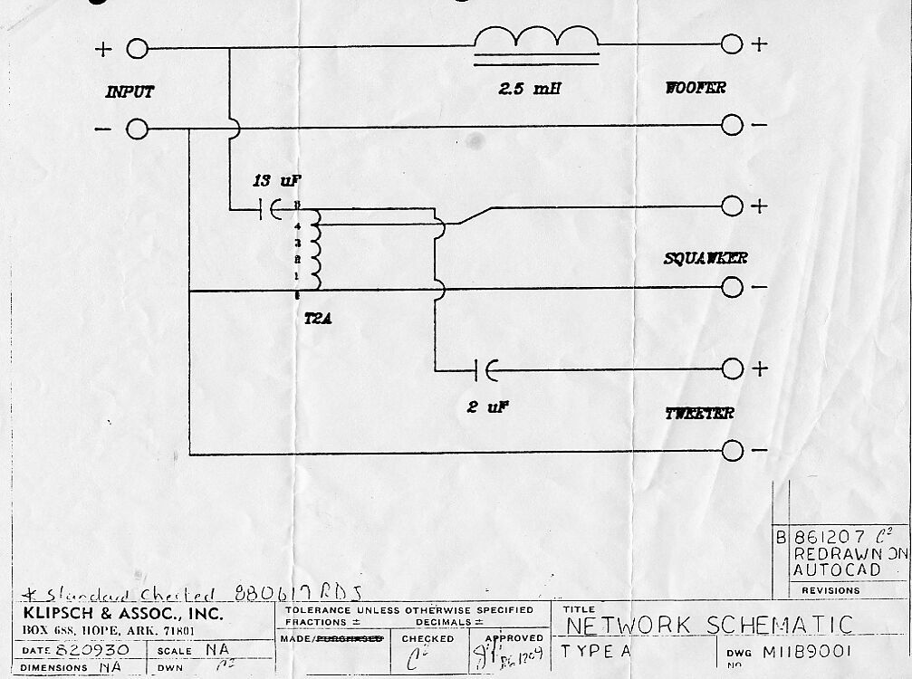
Quick question about the inductor used in the Type A network. As per the title, I know the inductor is rated at 2.5mH and I would assume a low RDC is called for but is the number specified? Will this fit the bill? http://loudspeakerfreaks.com/Product.asp?mfr=Jantzen Audio&part=000-5213&Product_ID=10693
-
Type A replacement caps slightly off spec
Robbie010 replied to Robbie010's topic in Technical/Restorations
Thanks Gents, however, this thread is now kind of defunct, thanks to a very kind offer from @mboxler in donating a spare set of autoformers to the project! 🤩 This will make the crossovers much easier to build using the original schematic, I just need to obtain the correct value 13uf and 2uf caps, which may be easier said than done over here in the Uk. 👍 -
Hello all, I have been given some great advice and guidance from forum members on the subject of the Type A network, I’m just struggling to get my head around this.... When looking at the original schematic for the type A network and viewing images of the the modern version, the 13uf and 2uf caps appear to be in series to the tweeter, is this correct or am totally mis-reading the schematic? As I read the schematic, the positive line runs to the 13uf cap, then to pin 5 on the autoformer (0 attenuation) then to the 2uf cap and finally to the positive terminal on the tweeter driver. From my current understanding, this achieves 0 attenuation via the autoformer and gives a total capacitance of 1.733 ohms from the two caps in series. Is this correct?
-
Type A replacement caps slightly off spec
Robbie010 replied to Robbie010's topic in Technical/Restorations
Sorry, Mike..... back with another query already. A friend has just had a quick look over my diagram and commented that on the original schematic, the 13uf cap appears to be in the signal line to both the squarker and the tweeter, is this correct? Does the original spec show 13uf in-line to the squarker and 15uf to the tweeter or is he reading it wrong? -
Type A replacement caps slightly off spec
Robbie010 replied to Robbie010's topic in Technical/Restorations
Mike, you are a star! Thank you for taking the time to help me out with this, it is much appreciated! I’m sure I’ll be back with other questions down the line. 👍🏻 -
Type A replacement caps slightly off spec
Robbie010 replied to Robbie010's topic in Technical/Restorations
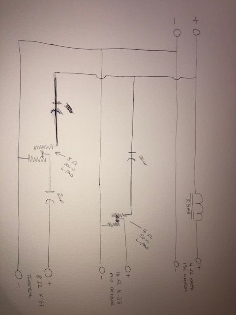
So the 2uf cap should be before the L-pad, not after it? -
Type A replacement caps slightly off spec
Robbie010 replied to Robbie010's topic in Technical/Restorations
Thanks Mike, I’ve done a quick sketch, does this look right?
-
Type A replacement caps slightly off spec
Robbie010 replied to Robbie010's topic in Technical/Restorations
Thanks, Mike. I thought the K-55 was a 16ohm driver? I was assuming I would need a pair of attenuators for each crossover, one for the tweeter and one for the squarker. Alternatively, I have found this: https://willys-hifi.com/collections/l-pad-attenuators/products/l-pad-attenuator-50w-16-ohm-wirewound-volume-control It seems that I could get an 8ohm Lpad for the tweeter and a 16ohm Lpad for the squarker?........ this is getting complicated! -
Type A replacement caps slightly off spec
Robbie010 replied to Robbie010's topic in Technical/Restorations
This is the Lpad that was revommended to me: https://rover.ebay.com/rover/0/0/0?mpre=https%3A%2F%2Fwww.ebay.co.uk%2Fulk%2Fitm%2F131570311873 Will this require a 13uf or 26uf cap? -
I am building DIY Type A crossovers for a clone la scala project. In place of the autoformers I will be using Lpads to attenuate the drivers. I have come across another issue in sourcing the capacitors specified (2uF & 13uF), whereby I can locally source polypropylene caps at 2.2uF and 12uF. Will this slight deviation from the specified caps be a major issue? Thanks.
-
Autotransformer Specification - Type A xovers??
Robbie010 replied to Robbie010's topic in Technical/Restorations
Thanks for the heads up. I have done some internet searches and found a UK based company that makes a T2A transformer, however, they cost £57 ($75) each!! 😵 It definately looks like L-pads or resistors is the only cost effective option, unless there is a forum member that is parting ways with an old set of Type A's or willing to break a set and ship the autotransformers to the UK at a reasonable cost. 😁 -
Autotransformer Specification - Type A xovers??
Robbie010 replied to Robbie010's topic in Technical/Restorations
Thanks everyone for your input. Im happy to see there is at least another (cheaper) option to the autotransformers. Although I’m capable in practical terms, woodwork, soldering etc, I’m not particularly technical so I’m sure I’ll be back here with more questions on this subject! 🤔 -
Autotransformer Specification - Type A xovers??
Robbie010 replied to Robbie010's topic in Technical/Restorations
I’m in the UK, 2 pairs of transformers from bob would set me back more than £250 ($330) with shipping and import duty. The as-built new Type A crossover from bob would be in the region of £320 ($420) with shipping & duty. I need to find a cheaper (local) alternative to make the crossovers feasible. -
Autotransformer Specification - Type A xovers??
Robbie010 replied to Robbie010's topic in Technical/Restorations
Thank you. I had been on the crites site before but didn’t notice the spec sheet. Now to try and source them locally! 😑 -
Can anyone please tell me or point me in the right direction where I can find the correct specification for the autotransformers used in a Type A crossover?? Thanks.
-
Sorry, I should have pulled this add, I managed to get a pair of K401 from the klipsch uk distributor. Thank you anyway.