


ngen33r
-
Posts
166 -
Joined
-
Last visited
Content Type
Forums
Events
Gallery
Posts posted by ngen33r
-
-
On 1/9/2021 at 8:00 PM, Kiowa said:
With the PDC removed I get 150V out of the D6 rectifier so that portion of the PSU is working now that the inrush limiter has been replaced.I did a full rebuild of the PDC with the schematic and parts listed in this thread. When I measure across the body of U4 and U5 according to your video I should see ~30V. I am only seeing 2.5 volts (with a lot of wild variation on the meter) and my AC limited supply bulb is pulsing bring/dim. Do you have any suggestions on how to better validate operation or troubleshoot the PDC board?here is a quick video:Update (even thought it looks like this thread is pretty much dead):
The problem was having the BASH board removed during testing let the Gate Drive that feeds Q7 float and damaged Q7. I also noticed Q14 was shorted as well (Both had been replaced during my rebuild once already).
Removing both Q7 and Q14 (both IRF530). Then replacing Q7, puts the amp in working condition from a power supply perspective. No more pulsing AC bulb. I see ~22VDC across the body of U4 and U5. I see the 5VDC across R70 and R71. Everything looks good. I verified the BASH board is getting 15VDC as well.
Problem:
The problem is when I populate Q14 (IRF530) the flashing AC limiter bulb is back and the board is unhappy again. Not sure what to troubleshoot on the Q14 side. The PDC and BASH seem to be working to me. Would this be an indicator of a bad U3 opamp?
Thanks
The BIAS could be way off or the volume is too high. Testing should always happen with the volume at 5% or less. If the outputs were replaced the pots will need to be adjusted. I plan to cover this in a future video.
The unmarked DIAC is a DB6 and can be sourced from NTE.
-
 1
1
-
-
On 1/2/2021 at 8:10 PM, Journey said:
So well on my way doing up the secondary side of the PS ... will be posting when done.
This is looking great. I have done this in the past, but I never had the time to fully invest into making the schematics.
Are you using Eagle or Kicad? I can just upload the schematic file for you. -
On 12/24/2020 at 7:42 PM, Journey said:
Hello Again ...
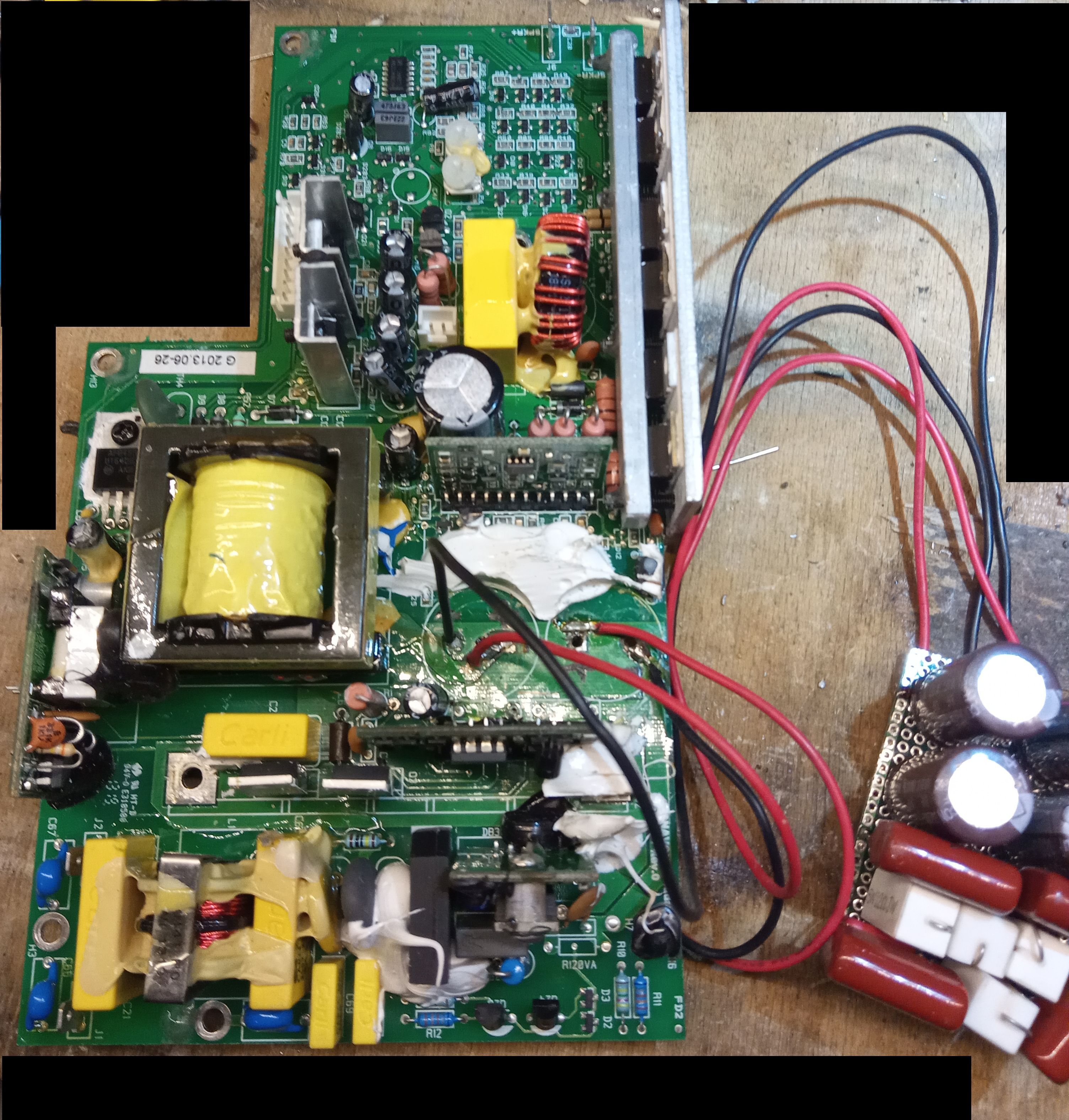
Well I have an update on my repair job. I recapped all PS brd except for the big disk HV caps and the ceramics as they IMO rarely have issues.
I hooked up the power and seemingly nothing happened. So checked the fuse in my Variac ... it blew. ( Note: I am using a 100 watt light bulb trick as current limiter )
Replaced the variac fuse and I saw a wisp of smoke and possibly a very tiny flash/spark ... cannot be sure if it came from the brd or it might have been my variac fuse
blowing again. The 1st fuse was 8 amps second was 5 both blew right away ... the 1st power up there was no action on the light bulb ... still not seeing any shorts on the primary side to cause main fuse to blow or light up the bulb ... also 2nd fuse at 5 amp saw no action with the bulb. This is very very odd as the primary is drawing more than 8 amps to blow an 8 amp fuse which IMO would indicate a dead short somewhere in the primary side but none can be found.
Again also ... no dead shorts on secondary either as far as I can say at this point. ALL that crappy glue has been removed so not an issue.
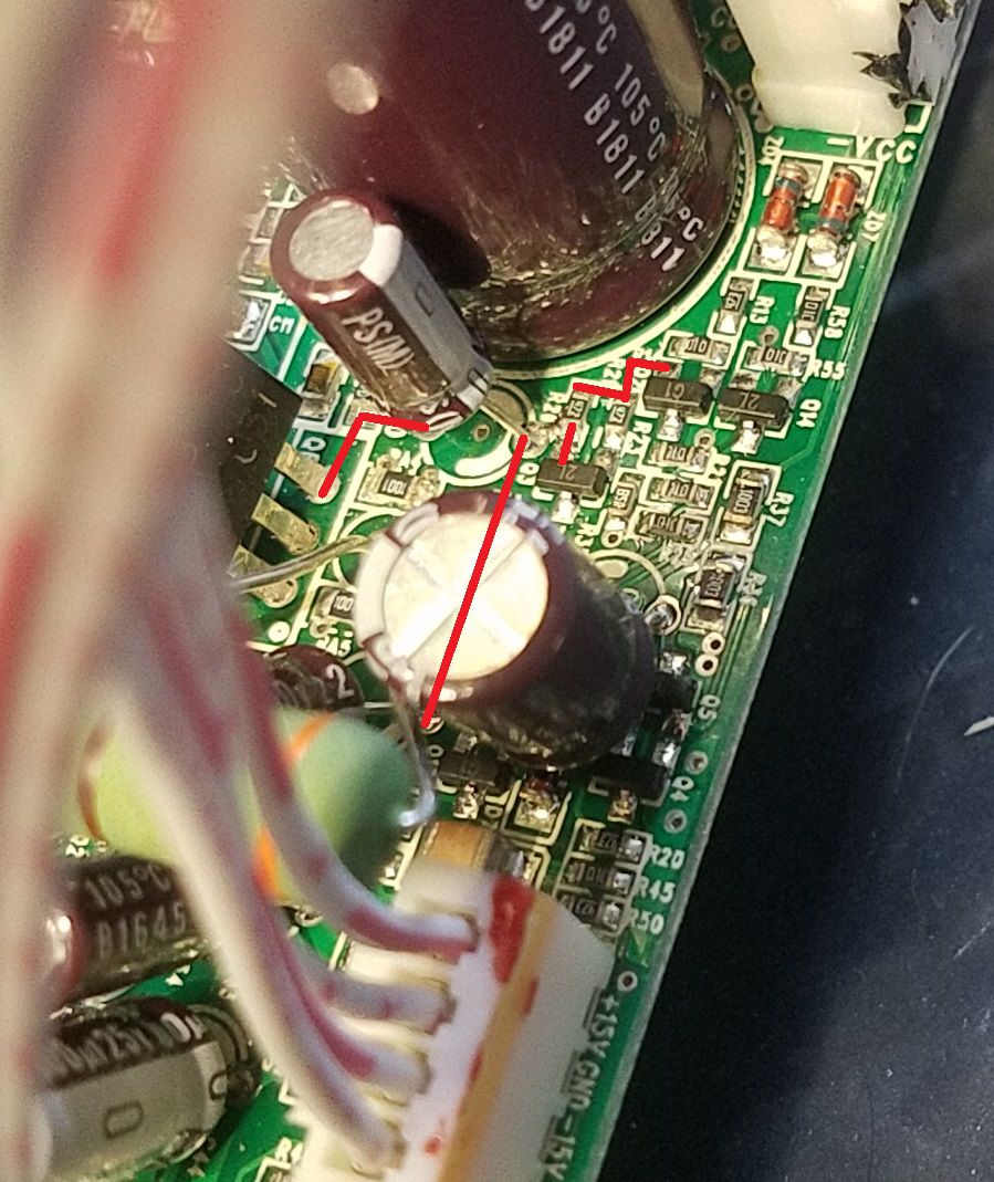
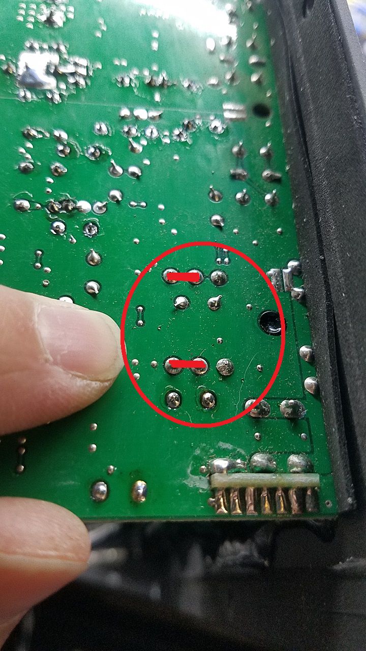
I did find an odd component with no markings on secondary side ... looks like a diode ... removed it and the pcb reference had two designations so have no idea which one it is.
One ref is D8 (off to the right) the other is TH3 (under the component) ... only connections to it on both leads run to the Conn to the amp brd ... pin 2 and pin 8 ... odd thing is no other connections on the main PS brd. It sits just in front of D16 on the far right side of the brd looking down on component side withe the amp conn at far right. On diode test it reads OL both directions ... on ohms it reads close to 150K. I don't think this has anything to do with the issues on the primary side but thot I'd mention it anyway.
So I'm back to square one AGAIN ! The obvious damage to C2 and C51(?) the two film caps at 1uF 250V were what I thought was the issue ... that wisp of smoke I saw came from that area ... can't imagine they cooked again as there are no shorts anywhere on the primary ... UNLESS it's the transformer maybe ? Tested the SMPS transformer with a Blue watcha ma call it and seems ok ...
If I can't fix this system and we just buy a new complete unit ... I WILL remove all components and draw up a schematic for this BE-ach ! ... at least for the SMPS to start with.
I'm hoping Wayne can advise where to go/look next ... any ideas there Mr. Wizard ???
PS>>> I removed all 4 MOSFETS on primary and tested them on a breadbrd circuit and they all tested good ... there was one however that did something odd 1st go round. When I pushed the button to switch the LED on ... it stayed on ... I then had to ground the gate to turn it off. 2nd time around it behaved as all the others ... had to keep pressing the button to activate the gate to turn on LED. And again after recapping and having the fuses blow on my variac still no shorts on the FETS.
PSS2>>> Just out curiosity ... how do you redo your VIA'S ??? Is there some kit one can get to do them ? Do you just run jumps ?
When I do failed via's I just run a jump thru the old hole and for burnt traces I try to do what you do but also just run jumper wires ... depends on what kind of mood I''m in LOL !
An 8A fuse will NOT blow with the bulb in series. Something is wrong in your setup. The most current that can be sourced would be ~1A before the bulb goes full on and clamps the current.
I replace the via with a thru hole repair kit. They are VERY expensive for what they are but needed IMO for a professional repair. -
I DO NOT LIKE PROVIDING THESE FILES
1. BECAUSE PEOPLE THEN PESTER ME AND ASK FOR THEM
2. BECAUSE I PUT A TON OF TIME INTO CROSS REFERENCING THE DESIGNS AND PARTS AND ALL THIS INFO CAN BE GOOGLED
THIS IS A SIMILAR POWER SUPPLY FROM BASH USED IN AN INFINITYTHIS IS FOR REFERENCE ONLY
AGAIN
THIS IS FOR REFERENCE ONLY
-
1
-
-
RECAP & repair the control board. No schematics are known to exist for these.
-
On 12/10/2020 at 10:14 AM, Kiowa said:
I am also having trouble finding parts and following this thread.
I have compiled the fragments of information and I am attempting to build a straight forward list of components that are often abbreviated with "Amp was recapped, replaced TH3, FETs, and Q5"
"amp was fully recapped with Nichicon caps" We now have a suggested manufacturer, Can we get a list of the caps and values?
"I use GE silicone 2". Good to know, will add that to materials list
"I had to clean and rebuild the PDC" Ok, what did that entail? Parts list please?
"replace the fets". Can we get a list of PNs?
"and TH3". OK, back to the original problem. Where does one find a "TH3"? Do we have a manufacturer and part number?
Suggested Parts list with links:
1) Q5 is SOT-23, it needs to be replaced with a TO-92 2N44011
2) TH3 (DSP104) replaced with ????
3) PDC parts for rebuild. What is all involved in a PDC rebuild? Parts??
4) FETs replaced with ???
If you can help fill in the blanks I can edit this post and include links for the parts.
DO NOT BUY PARTS FROM AMAZON, DON'T DO IT!
https://www.digikey.com/en/products/detail/on-semiconductor/2N4401BU/1417https://www.digikey.com/en/products/detail/epcos-tdk-electronics/B57211P0100M301/2781797
PDC parts are listed on the schematic I made and posted. Rebuild requires replacing what is bad and what PDC you have. There are 2 different versions with different parts.
FETS are IRF730/740 depending on the amp you have
Everything is available on DigiKey or Mouser, or any reputable parts supplier. -
-
On 12/14/2020 at 2:39 AM, repaireneeded said:
Hi,
I need your help, how can I repair this does anybody have schematics what part comes to R26 and how is C80 connected.
Here are the pictures...

Or if anybody can repair it I am from Europe.
-
On 11/30/2020 at 2:40 PM, trasman said:
Do you know how to bypass the two switches?
OFF / STANDBY / ON
0° / 180°
My kid just broke them off and now the sub-woofer is acting strange.
I'm fine with it being always ON and 0° as I could start unplugging it.
Cut off the legs and solder jumper wires in the position you want
-
On 11/25/2020 at 2:27 AM, dmitrev said:
Thank You Dear. What blog is proper for me, boards of sw10 seems close? Please, delete my posts if they are in wrong topic.
SW-10 REPAIRS SHOULD GO WITH SUB-10 AND SUB-12 I WILL REVISE THAT TITLE IF I CAN EDIT IT. PLEASE MOVE THIS POST IN THERE. THANK YOU
-
-
Here is that part:
-
1
-
 1
1
-
-
-
The 104 is an Inrush Limiter
https://www.datasheet4u.com/datasheet-pdf/Voltts/SCK-104/pdf.php?id=675090https://www.digikey.com/en/products/detail/epcos-tdk-electronics/B57211P0100M301/2781797
If that is blown 99.999% of the time your fets are toast too as well as some other passives.
-
-
-
10V is high. 8V is normal. Something else is wrong.
-
18 hours ago, dmitrev said:
Hello Dear. Thank You for the good topic. Started to repair Klipsch sw-110 of my friend. SMPS main electrolytes fried. Replaced. Fried again in a seconds. Made additional board with better capacitors, added RC groups to stop HF(I suppose main electrolytes boiled from the high freq). Now there is no warming of the capacitors, but, seems SMPS not running. Started to draw topology - seems strange to me, not half-bridge, IRF730 connected S-D, D-S, some strange buck - inverter? working on only one of the capacitors? or I'm already blind and stupid
... started to search in the net. And... I'm here Can You help with some drawing of this model?
No drawings or schematics are known to exist to the public at this time.
-
You need to de-solder them and solder new ones in. If those are blown, you will have more bad things than that.
-
Here is an RT-10 repair and what I learned.
-
On 10/31/2020 at 5:21 PM, Allan B said:
I have a RPW10 that the local repair shop said the sub amp is NFG and needs replacement but they cant find any parts.
Is this correct or is it a case of trying to just sell me a new one.
Please and thank hyou.
Allan
These amps are always fixable even if almost destroyed.
-
-
And so it begins. I have started my video blogs and will continue to support the repair community with detailed videos of how I do a repair.
-
1
-
-
RSW's start with the caps and start tracing the circuits. These are not easy.


RT-10 / RT-12 REPAIR BLOG
in Technical/Restorations
Posted
I have not made any test fixtures. I keep a spare power supply that is known good and use that as a test rig. You can always socket the components for testing then remove the sockets for final install.
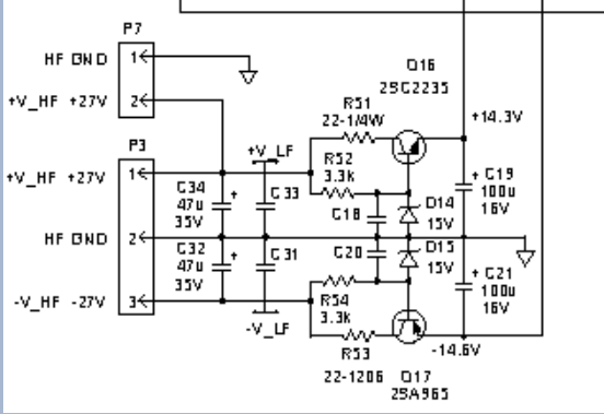
I have attached my version of the schematic.
660045-1.sch