Journey
-
Posts
29 -
Joined
-
Last visited
Journey's Achievements
Member (2/9)
1
Reputation
-
Hi Jaboc .... Have you done any poking around for shorts /bad components ? I'm still working on mine with limited success ... a few dumb blunders on my part set me back a bit ... some components were hard to find out they were bad but I'm about ready to power up again and see how it goes. I'm in western Canada ... where are you located ? I'd be willing to give it a try if it doesn't cost ya too much to ship here.
-
Hi Wayne, Thanks again for that latest info/response ... as I stated above, I removed and tested the IR2153 and it was fine. Using this Vid as a guide. The schematic for the tester is shown in the vid. With all being well on the Ctrl Brd and the bash brd removed ... question ... Can you power up without the bash connected ... my thinking is to see if the primary side is functioning properly now that I think the primary is good to go. I would appreciate your thots on this.
-
Hi Wayne, Thanks for getting back here ... I kinda thought using the variac would be a no go. Amazingly, those backwards caps survived somehow ... the one on secondary side was measuring just fine with a good LCR meter (probably because no voltage was getting through to that side anyway) and an ESR tester so put it back in as for the two primary siders ... I put the old ones back in as they tested good as well on both tests. The two new ones that were in backwards tested kinda ok ... they went out of spec for uF measurement both dropped down to below 900uF. I removed my control board again and tested all the new replacements I put on and it checks out good. I found a cool little test circuit for testing IR2153 and it seems fine. I was wondering if you cooked up a way to test that brd out of circuit ? I removed the bash board as well and could find nothing amiss there save for the IC which i have yet to determine if it needs to be replaced, everything else on it seems in order. Not sure if you saw my schematic for the basher ... I used your original and cleaned it up a tad and added all the missing pinout numbers per the signal labels you provided on your version. I also did up a pcb layout for the ctrl brd as per my version of it which is identical to one of your detailed inverted pics of one you had. I found some of the component References were not the same as mine. Since I blew out almost all the thru holes on the ctrl brd I was wanting to put a socket in but having a hard time finding something that will accomodate the square leads on the brd. As per your comment about the CD+ supply at 8V ... I knew there had to be a catch to that somewhere ... now what you said makes sense ... it varies according to input signal strength .... interesting idea ... wonder who cooked that one up ? One other interesting thing to note since I came back to work on this thing and found my errors and 2 more blown components ... I use a 100 watt bulb inline for current limiting like you do ... I'm not sure it's working tho. The 2 inrush current limiters I found were blown ... less than 1 ohms ... which explains why my variac fuse was blowing everytime I switched the power on full ... but the light bulb never even flickered or glowed as that inrush pushed through ... shouldn't it have given some sort of indication here ? of a large current flow ... more than 7 amps as per the fuse in the variac. I can't imagine why it didn't even start to glow even a bit ... I heard you mention in one of your video's that that bulb should limit current to about 1 amp ... am I wrong ?
-
Well boy was I wrong ! ... How the hell can you run a sub amp on 8 volts ?! There's no DC boost on the amp board so ... ???? wth ?
-
Hi All ... I just finished a marathon of KiCading ... almost 24hrs straight ... took a food break and that's about it. I did up a pcb layout for the Control Board for the RT-12 ... just have a few finishing touches and she's a done deal. I also did a schematic of the Bash board that Wayne posted a while back using my Bash as a guide. As I noted on the schematic, several resistor values were different. My Bash is 660047 Rev 3 RD so one has to go from there. Here is a photo off my laptop. I'll probably be doing a pcb Layout for this bash as well but later ! I'm all KiCadded out ! I may post the KiCad files down the road a bit.

-
New question for ngen33r ... I got back to fixing my RT-12 SMPS and found a few errors I made ... all the big filter caps I had in backwards. Luckily no explosions ! Can't believe I did that ! The two inrush limiters were reading less than 4 ohms each so they were gone. Replaced all the large fets and diodes ... rebulit the ctrl brd ... now when I try powering on at about 50 volts on the variac ... no voltage on the ctrl brd IC pin 1 ... any ideas ? Have you done a video that focuses on the ctrl Brd ?
-
Hmmm ... good question ... I'm guessing it's gonna be fairly high to power the amplifier ... could be around 40 to 60 volts DC ... I'd guess. I have another sub, different mfger, that has a bad smps and it's DC output was labeled at 60 volts DC for a 300 watt amp output.
-
My apologies for my errors 1st time around ... I hope it didn't cause to many brain farts for anyone ... it's not an easy task to do something like this ... I spent lots & lots & lots of hrs so errors are bound to happen.
-
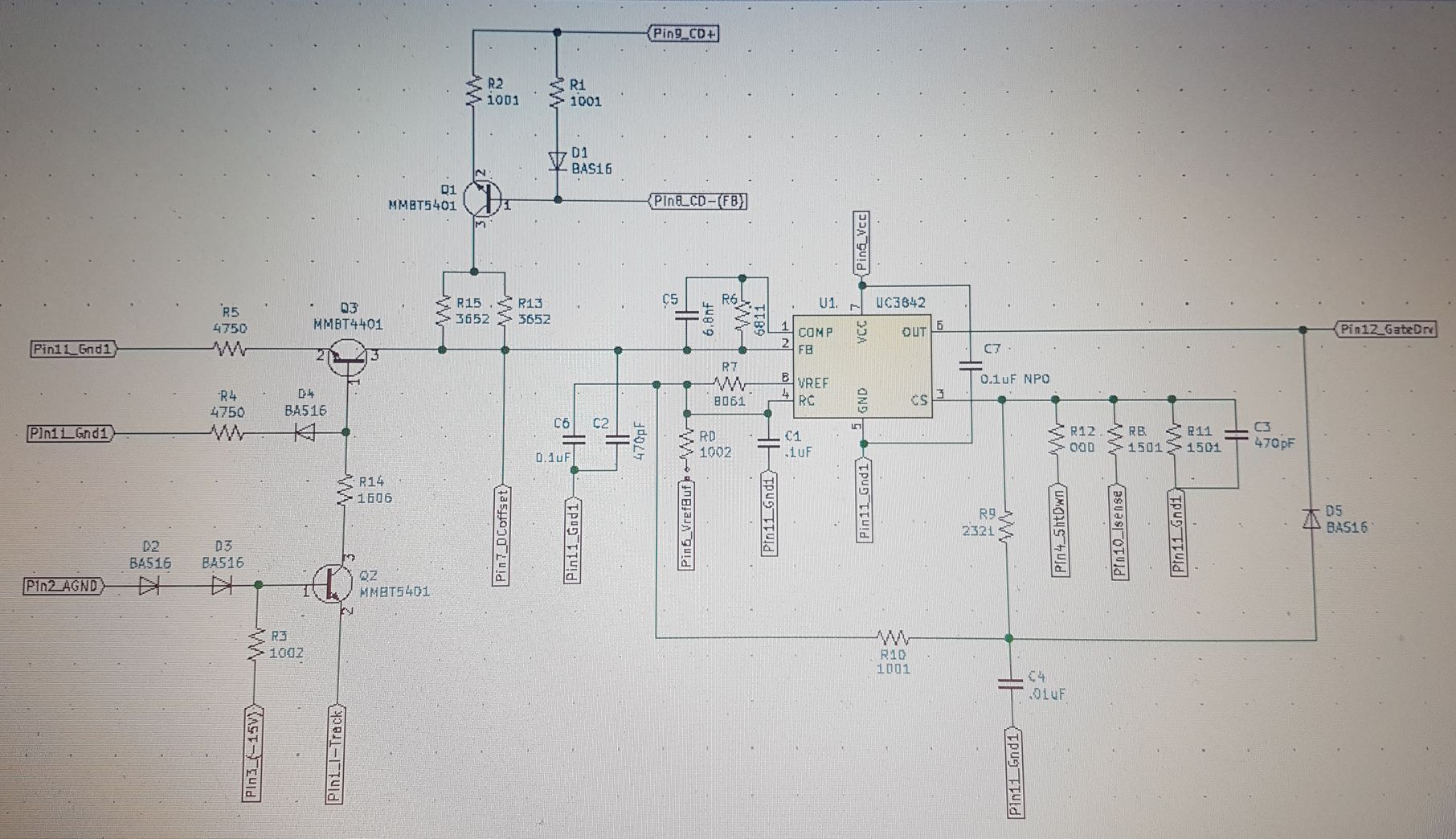
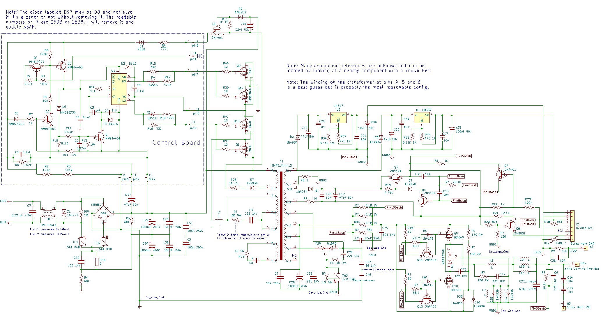
Hi All .... Journey back here again ... I have an update for the RT-12 schematic that I drew up last year. I finally revisited repairing the smps and found several mistakes I made on my recap job (all my big filter electro caps were wrong polarity AND found the two inrush current limiters (SCK-048's) were shot. During all of this I found several mistakes in my schematic which are now corrected. The 2 SCK-048's were not reading proper resistance ... supposed to be 4 ohms each but measured like dead shorts so kept blowing the fuse in the variac I was using to power up. I may have to repair the control board again ... not sure but may have blown it up due to my errors. Here's the KiCad file with the corrections. There still maybe some errors but the main corrections were on the primary side and pretty sure I got it all straight now. Also renumbered the pins on the smps xfrmer. I went over it many times while working on it and can't believe I missed as much as I did. This zip file includes the ctrl brd schematic and details jpg ... for some reason I couldn't find the other brd schematic on the secondary side ... thinks it's call the bash brd ? Edit ... I found a few more mistakes on my rework of the control board schematic ... I knew I would find a few more. So am reposting it again here. Recommended to delete the old file and download again ... otherwise brain farts may ensue. I also changed the resistor values to the original SMT codes. Klipsch RT-12 SMPS Full.zip
-
Thanks ... I have done lots work drawing schematics so all I needed was a PS to follow and lots of time to do it. Luckily my client was in no rush so I was able to have it around for a couple months.
-
Hi Gslettum ... On my PS the Bridge part number is shown in my latest schematic posting ... It is a KBU8G bridge. I'm guessin it's at least 600V and some beefy amps ... at least 6A ... anything above this will do 8A 10A should be just fine as long as the footprint fits. Here's the datasheet for it ... https://pdf1.alldatasheet.com/datasheet-pdf/view/62072/GE/KBU8G.html
-
Hello Agin All ... I have completed the full schematic for the PS for RT-12. I have got nearly all component references covered for the primary side save for 2 as well as part numbers. Secondary side there are still some references that are not known but I think I got all the part numbers. Again I stress that there may be mistake or 2 but I'm 99.8% sure I got it right ... anyone can see an error let me know and I will correct the schematic and repost. If anyone wants the actual KiCAd file let me know and I will send it or post it although I'm not sure how I could post the KICad fie maybe someone can show me. Klipsch RT-12 PS Full.sch
-
Cool ... thankx I'll update and I have also updated the primary side with some additions of missing part numbers.
-
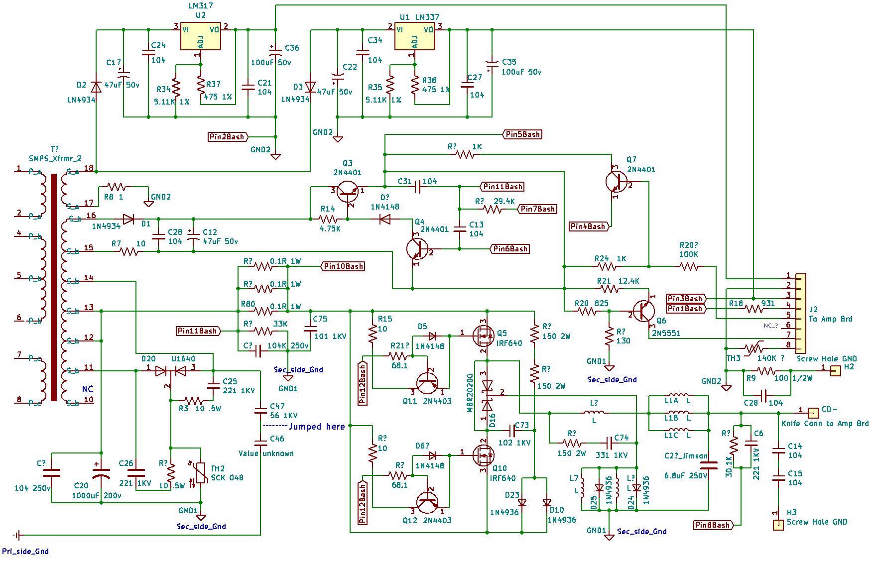
Hi There again ... well I'm back ... I finally finished up the schematic for the secondary side of the PS. Obviously I cannot gaurantee 100% accuracy but I'm confident it's like 99.8% close and as you will see many Component reference numbers are missing due to being hidden ... didn't fell like desoldering so many parts to get at them. Some part numbers are also obviously unavailable. One can deduce where the part is on the brd by just navigating the schematic and making comparitive observations. Anyone out there ... feel free to point out any errors and let me know so I can make those corrections ... I spent many many hours doing this and triple checking and more as I built it up. I forgot to ask you Wayne if you did up a schematic for the BASH brd ? If so could you send it so I can rework if nessecary to include it on this schematic. One other thing I forgot to do is make a note on the page about the 2 isolated GND's .... GND1 is marked as the main secondary side ground and GND2 is for the regulator section mostly and the Bash Brd ... so they are somehow isolated ... not sure how yet but the two are distinctly separate.
-
HI guys ... thanks for the schematics posted ... I have rebuilt the control board as far as all the semi-conductors go ... resoldered all smt resistors ... not sure if a guy really needs to do the ceramic caps ... they rarely fail in my experience. As far as I can see so far with the schematic is that I'm 99% sure I got it right when I did my whole primary side schematic where the pinouts are concerned for the ctrl brd. I'm still stumped as all hell as to why this PS is blowing my variac fuses. I was wondering if the ctrl brd is not functioning properly ... would it cause the FETS to stay on all the time and this would or should blow my variac fuse ... but I would also think it should or would take out at least 1 or 2 fets as well ... any thoughts out there ?