Al Klappenberger
-
Posts
3918 -
Joined
-
Last visited
4 Followers


Al Klappenberger's Achievements
Forum Ultra Veteran (5/9)
22
Reputation
-
I am getting tired of this "just another way to do it" crap! Putting the transformer at the source end of the filter is just as much "another way" as the method Henry Ford used to start the engine on his model "T". It had a crank on the front. You would slowly turn the engine around with the crank until you felt the compression stroke begin. You would then yank the handle quickly to start the engine. My father showed me how it was done on the old model "A" he had when I was a kid. The engine would start every time. He also told me about his "Model T wrist" that was still hurting him from the day years before when the engine on his "T" kicked back and nearly broke it! Now days, we turn the key and an electric motor starts the engine for us. I suppose the electric starter is just another way to do it, just as good as the crank! BUNK! Putting the transformer at the wrong end is just an OUTMODED way to do it to a few people have remained invested in! Then there is Ahoooga horns. Showld we keep using those. After all, it's just another way to make a big noise! Quit listening to people who are invested in old outmoded ideas and keep promoting them to make a buck! NOTE: I have received a "warning" by the moderators... I am out of here. I DON'T NEED THIS FORM TO SEEL MY STUFF! The blind can continue leanding the blind!
-
Mark, Actually you are correct. I usually don't talk about this becasue it's just more of the same. Remember that the K33 is actually 6 Ohms in sereis with 1 mHy voice coil inductance? Well.. The low crossover (woofer to squawker) is at 6 Ohms. The other networks I offer are 8 Ohms. By the parallel resistance equation Rt = 1 / (1/r1 + 1/r2)) so, 1/(1/24 + 1/8) = 6 Ohms. This matches 8 Ohms to 6 Ohms. The other reisitor is 24 Ohms! AND, I don't want to hear more crap from anybody about reduced efficency! It is NOT going to run your electric bill up! The 24 Ohms is a 5W resistor when a 1W would do. Same with the 10 Ohm across the transformer. I use 10W where a 2 W would do nicely. Have you ever heard of any of my networks getting hot! NO, and you won't! Al K.
-
I thought this stupidity was done with! This is an example of somebody talking about things he clearly doen't understand! I thought I tought him better, I suppose not! The resistor is to absorb all the possible impedances created by moving the transfomrer taps to whatever filter it terminates! Infinity Ohms in parallel with 10 Ohms is 10 Ohms. This means even an 8 Ohm filter will see no more than 10 Ohms even with the driver completely disconnected. The is only a 1.25:1 missmatch! Putting the transformer at the source end only continues to be done becasue PWK did that! He did it becasue the 13 uF of the AA (for example) would be aout 50 uF if it was in a 50 Ohm filter! In his day a 50 uF cap would be unreasonable. THE ONLY REASON TO KEEP PUTTING IT AT THE SOURCE END THESE DAYS IS TO JUSTIFY BUILDING OUTMODED DESIGNS! Dean, it's time for you to stick to your day job! Al K.
-
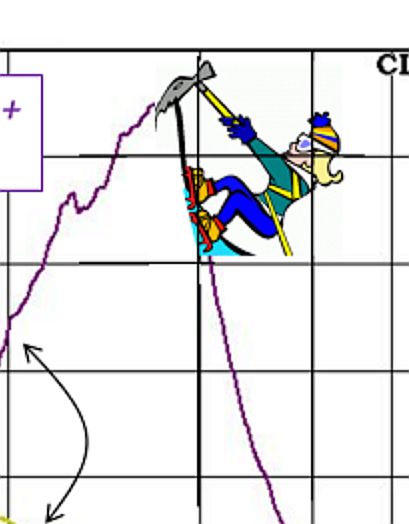
For anyone who hasn't followed this very closely, this is Belle. It's the little figure climbing the huge mountain formed by the impedance cure of John's transformer in one of his plots. Al K.

-
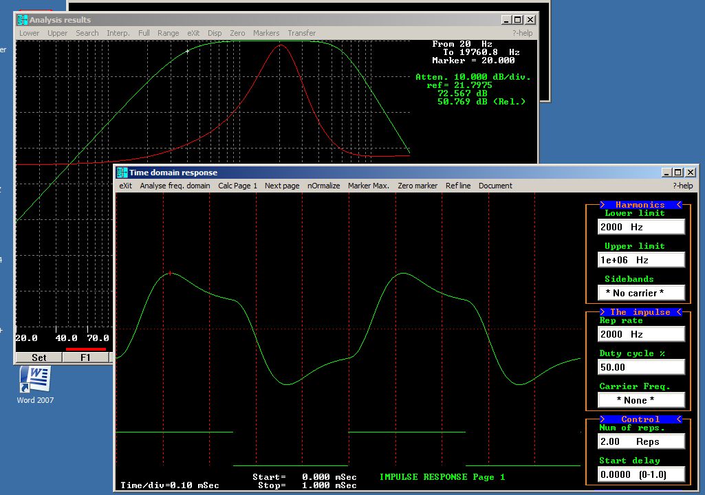
I said it wasn't worth the trouble to calculate the time domain response of your "thing" but I changed my mind. It was fun! Here's what a 2KHz square wave would look like out of your midrange channel. Al K.
-
WOW.. This plot shows very cleary that my Universal beats the tar out you thing! MAN! This is the ultimate insult to the Klipsch community. Do you really think the people interested in this thread can't read a plot! Speaking of FFT.. I could always use the foruier analysis section of PCFILT to show the impulse response of both networks (in the time domain you mentioned earlier), but it's not worth the trouble! You just keep embarrassing yourself to anyone who knows anyting! GO AWAY! Al K
-
Your next plot: Here you have two plots on top each other. The difference is simply that you have a different value inductor in series with the K33 woofer than I do. That's why the circles move apart in the vertical reactance plane! BIG DEAL! The reason the "Universal" is universal is because it has a 1st order filter in the woofer channel. Just like yours. 1st order filters are so blasted sloppy that it doesn't matter what inductor you use! It will work equally poorly with any woofer. All a 1st order filter does is make two drivers play nice together! Take the inductor out completely like PWK did with the AB network for the Belle Klipsch and you will be left with the K33 alone. If you do that the circle will shift the other direction. This is yet more of your techo double-talk, or more accurately, double vision! Al K
-
The next plot. The polar one: Now this is very clever.. Just stick up a plot showing the same thing as before again. The travels of Belle around in a circle. It's just REPITITION! We know what the complex impedance of the K33 looks like. I WENT THROUGH THAT EARLIER! Another trick associated with techno double-talk. Say the same thing over and over using different fancy words, or plots! We'll dazzle them with a round one this time! Al K.
-
@@John Warren, @@John Warren, 1. The NRE-net has a very large reactance associated with the autotransformer, horn reflections, etc. The reactance is highlighted by our little mountain climber (let’s call her Belle). * This is because your transformer is in the wrong place! 2. Below about 500Hz, the two plots meld together as the K-horn Z dominates at lower frequencies. * It dominates because the crossover directs the energy to the woofer. This is why you see the resonance of the K33 at about 36 Hz. The impedance plots diverge because the amplifier sees you poor midrange filter above the 400 Hz crossover. There is NO GOOD REASON FOR THAT! 3. The BULK of amplifier power is delivered to the Klipschorn bass unit so amp loading, if altered in anyway why the speaker loading, is going to be the result of this reactance. * Double-talk! It's the inductive reactance of the K33 woofer. Same with the phase plots. It's the K33 your looking at! None of this is relevant to the network. If you had bothered to look at my earlier posts illustrating the effects of the K33 on the lowpass filter of the ES300 network you MIGHT understand that I explained this in detail! 4. Now, the midrange on the ALK is sort-of constant Z but it's over a region where the amp really doesn't care. * And just what range is it that the amp doesn't care about? A good amp doesn't care over any frequency range. This is the simply an excuse to do a crappy design. A little SET amp DOES care though. It can't handle extreme peaks like yours shows, at ANY frequency. It actually louses up the frequency response as the little amp unloads! There is no good reason to subject any amp to a 23 Ohm peak in the middle of the midrange! ------------------- * This entire set of plots simply illustrates a poor design. YOURS! DUMB!
-
I have noted that in may cases JW will resort to Techno double-talk to cover his butt when he runs out of serious points. Now that the obscene items have been taken down by the moderators he has nothing else left! These latest plots about my Universal are such a total fantasy that I don't know where to begin! It's going to take me a while to travel to never-never land to try to understand how some of that crap could possibly have been fabricated, but I will! WOW! Al K.
-
Warren, How about you posting the schematic and parts values on your network so I can do a little "simulation" on it. Everybody has had the design and values on my Universal for years. Including "group delay", as if it mattered! You might start by telling us what it actually is! All the "simulations" I did on yours was by assuming you got the parts values correct for an ordinary 3rd order Butterworth diplexer. That might not have been a valid assumption. BTW: Your measurements are all screwed up! Al K.
-
It was only funny to me! To the general public is was juvenile and obscne! AL K.
-
Yep, that's why I got banned! I will be happy to be banned again. Then I will be needing another sock puppet. Are you up for the job again Dean? You did a real good job on the Eliptrac HF thread a while ago! There was always a need on this forum for somebody to identify the snake-oil. It always seems to get interpreted as a personal attack, no matter how carefully the critique is crafted. I might as well go for it! An another thing, I don't need this forum to sell my stuff! I got all the work I can handle and then some. That's why I foolishly let you build my Universal! NEVER AGAIN! Al K. Edit: I forgot to mention: Dean, you shouldn't feal slighted. There's lots if insults scattered around this thread for you too!
-
I agree, I think Lee and I have accomplished what we intended to do, debunk some snake-oil. Once this thread has run out of gass I plan to retire back to oblivion where I came from. It's entirely up to how much more techno double-talk gets put up. There is simply nobody else around here to do it. BTW: I sure wish I knew how to spell! Al K.
-
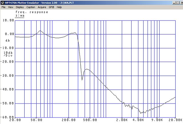
Just for kicks, here's the ES300 lowpass as measured using the other simpler method. It's real easy to do, you just ...... On second thought, I better let a certain Piled High and Deep engineer reverse-engineer the procedure! Al K.