Al Klappenberger
-
Posts
3918 -
Joined
-
Last visited
Content Type
Forums
Events
Gallery
Everything posted by Al Klappenberger
-
External speaker cables vs. internal speaker cables
Al Klappenberger replied to lyeerluna's topic in Technical/Restorations
Brian, Fancy speaker cables is one of the big scams in audio! All that is required is that their DC resistance be a tiny fraction of the woofer voice coil resistance. Ordinary hardware store lamp cord satisfies that requirement perfectly! All you need to do with the wires inside the speaker is to see that they are not corroded. Check to see that all the spade lugs to the connections are clean and that's it! You might loosen each screw and re-tighten it. That can improve things sometimes due to unseen corrosion under the lugs. Al k. -
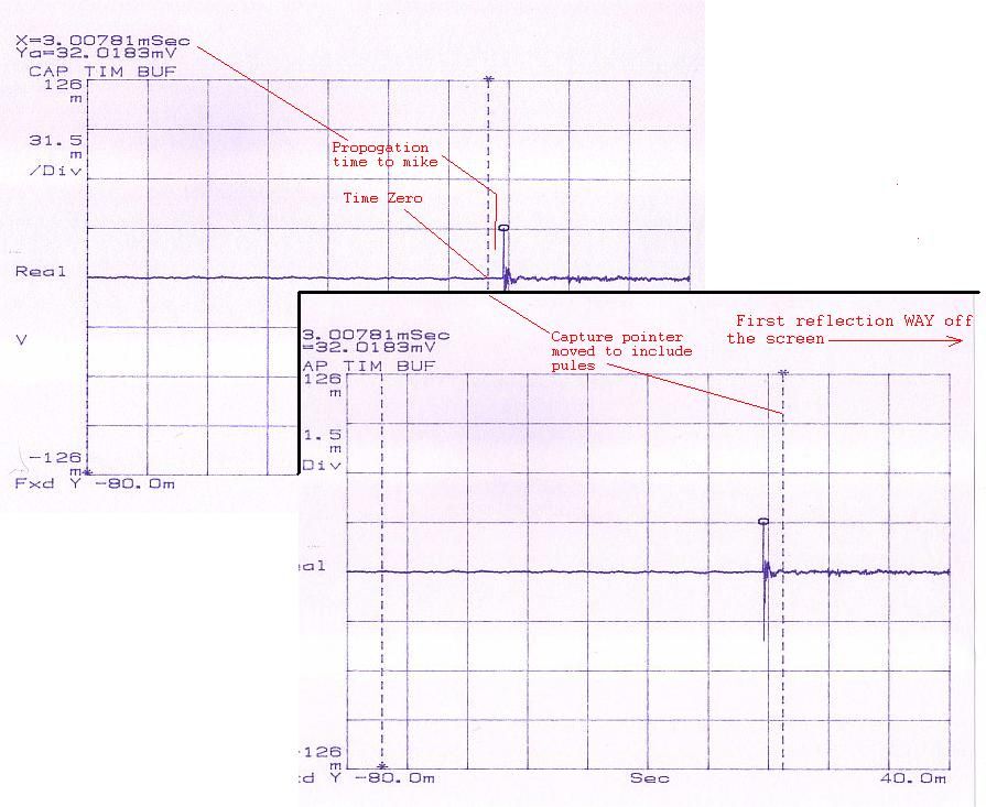
Mike, I think you got it! The explanation in the link you gave jives with what my thinking. I just fiddled with the menus on my HP 3563. There is just no way to narrow that interval window down. All I can do is very the position of the window or delay the impulse in time. It's just not a very good arrangement! Even doing anechoic measurement requires a negative trigger delay to put the impulse into position so that the wide window ending time will be adjustable to before the impulse to some time after it. Unless I'm missing something, it STINKS! Al K.
-
Shawn, "A waterfall isn't the same as windowing a measurement" It looks to me that it is. At least one is required to make the other. You are moving a small window in time (a segment or interval of time) and computing the spectrum during that interval. Each segment is converted to a spectrum and displayed one in front of the other which looks like the waterfall. The "capture pointer" information in the HP 3563 manual is very confusing. I need to look at it again with this idea in mind. I have been using it simply to include everything after the impulse up to but excluding the first reflection to generate anechoic response. I don't think it's adjustable in a way that's going to do this. The graphic shows a captured impulse off the HP 3563a. The window is between the vertical dotted lines. It's just to wide! Al K.

-
Shawn, Rudy, I just took a closer look at the software you suggested. It looks like it requires a computer with a sound card. My computer has none and there is no spare slot to install one. My old computer did, but it's in the attic! I want to gear everything I do the the HP 3563 analyzer anyhow. It has the impulse generator in it. It has and adjustable window for the time capture feature but I don't think it will look at a narrow enough time interval. Shawn, I think the SD380 analyzer had this capability as an option. Does the you have / had have it? Al K.
-
Shawn, That looks interesting. I'll try to look at it. It's just a matter of getting the lead out of my posterior! Thanks, Al K.
-
The Forte II design has been added to my web site downlaod section. Look for the dump truck icon on the left edge menu. Al K.
-
The new design was accidentally posted to a review of the original Forte I network by mistake. You can find it here: Forte' upgrade End of page 1 and Page 2 The new design will be on my web site for download eventually. Al K.
-
I need to look into inpulse waterfall plots. The waterfall plots I was thinking I could do are for polar dispersion. That's something different. May Lee Clinton can do it. Al k.
-
A time-aligned top end - Part II
Al Klappenberger replied to Al Klappenberger's topic in Technical/Restorations
With a LaScala there is no need to cross over down at 400 Hz. You can raise it to 500 Hz and use all sort of combinations. The minimum I would use would be my AP12-500. It will operate 2-way. Al k. -
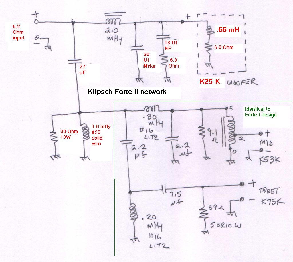
Here is the board layout expanded to show the changes needed for the Forte II speaker. The values in magenta (deep red) are for the changed values over the Forte I in black. AL K.
-
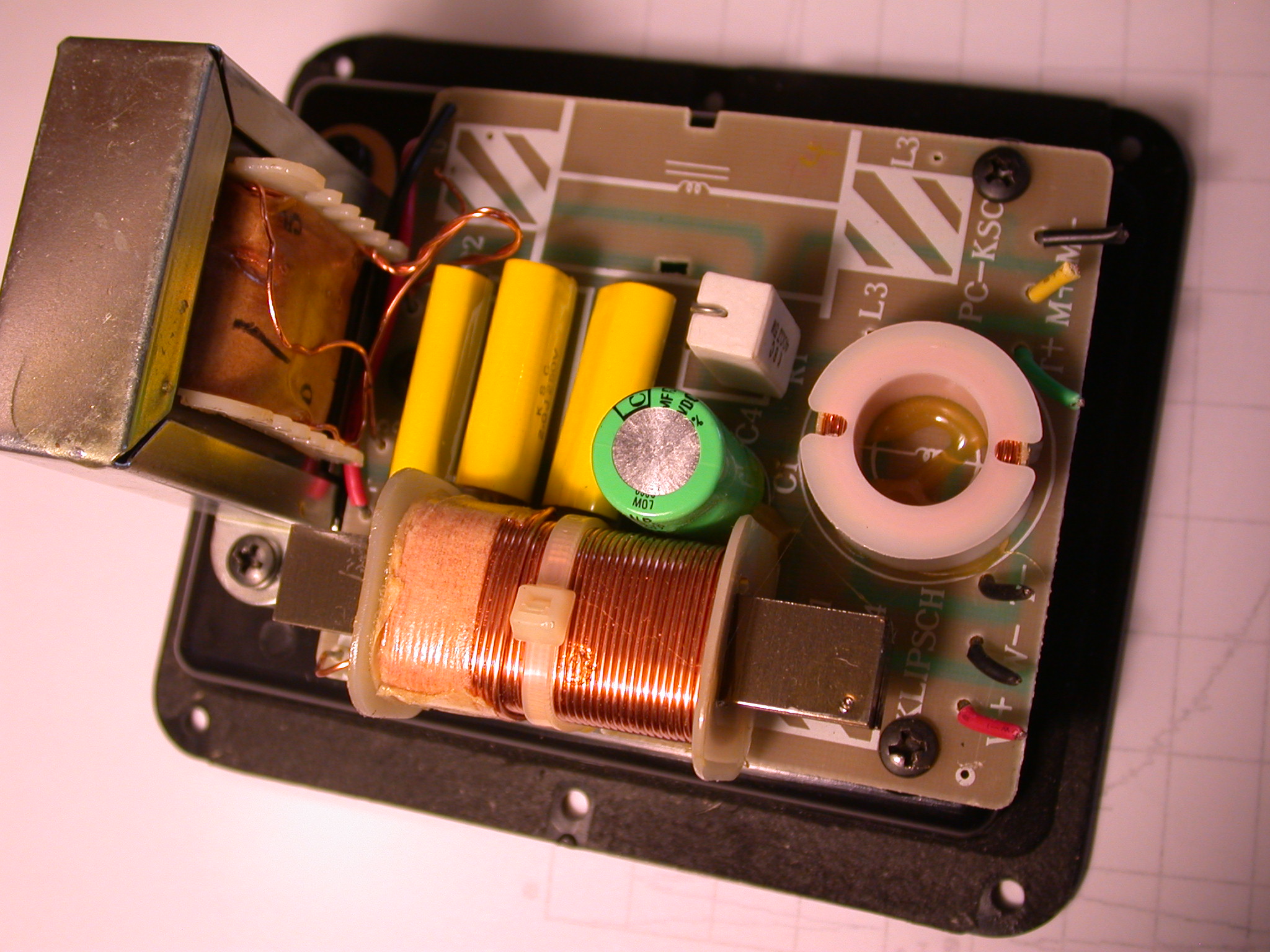
Here's the OLD forte II network. It looks identical to the Forte I network. The circuit is the same with just slightly different values. BTW: The picture was taken with a Nikon Coolpix 995 camera I just got off eBay for $23. I like it better then the Coolpix 4500 I paid hundreds for! [8-|] Al K.
-
The network design for the Forte II is done. I haven't built it, but it's so similar to the network for the Forte I that I don't think I need to build it to prove the design. The only changes are in the low crossover to the woofer. The part values have changed over the Forte I design. You can find the thread on the Forte I crossover here: http://forums.klipsch.com/forums/t/120300.aspx The schematic is below. The changed values are in red. Al K.
-
Mike, I think that's saying that impulse response is another way to look at frequency response just a group delay is another way to look at phase linearity. I'll buy that! Al k.
-
A successful conspiracy designed to drive the Klipsch community to drink! Al k.
-
MIke, I can do impulse but I am confused about it's value. A FFT analyzer like I use (HP 3563a) will comput the frequency response from the impulse response. It's called time capture by the menus. I do it sometime to simulate anechoic frequency response above a certain lower limit. That implies they are the same thing. My filter software can calculate the impulse response of a filter by summing it's frequency response and phase data from analusis (S12 parameter). It's called "fourier analysis". When Lee does the polar plot I can display the waterfall data from that data. Remind me when I get the polar plots posted. AL k
-
Guys, Take a look at this. Dave made the big-time! http://itishifi.blogspot.com/ I didn't know about this sit till just now. There's some other neat looking stuff there too. Al K.
-
Boydfp, I usually see posts removed by simply editing the text down to just say "Never mind!", or "Double post" or "Retracted" for example. AL K.
-
I think you will have at least 40W into 16 Ohms. Al k.
-
Rudy, Impedance doesn't matter to power. It only dictates the ratio of voltage to current. Power is voltage times current. Simple Ohms law. R (or Z) = E / I and power = E X I. Al K.
-
The impedance of the driver doesn't matter on my networks. 16 Ohm drivers are simply set 3 dB hotter on the transformer for the same power level. You can't use any other driver then the K55 on the Klipsch networks or the mid-range and tweeter will both be operating at once. The AK4 network has equalization in it for the K55x that is also wrong for other drivers. Moving away from the K55 always requires changing the stock network. For bi-amping it also doesn't matter. Most amps either don't care about the impedance or have separate taps for each. Al K.
-
Bob Crites is an authorised retailer for the Faital Pro drivers. That's good news. Al K.
-
Jc, Yes. I packed up the driver on Dave's K2 Edgar type horn and shipped them to Lee Clinton this morning. Doing polar plots on that horn will answer the question about the curved side obscuring the driver up high like it seemed to do with the coaxial DCX50. He still has the Eliptrac prototype horn there too. Al K. .
-
616gc, There is one other thing you really need to try. Replace the K400 horn! Al K.
-
616gc, The frequency reigon you are talking about is noted for a peak in the response. This might be what you are hearing. The AK4 and later networks have a simple equalizer in them to attenuate that reigon a bit. Most people like that peak even thoug it's not technically correct. The way to fix it is an external active equalizer, Al K.
-
616gc, I think I misunderstood! The Bruce Edgar type horn, as he described it in his original article, used drivers like that with about a 4 inch throat. He found that choosing the best one was a major trial and error job. That kind of arrangement would be a possibility. I don't know what would be the overall benefit though. I suppose there's a world of possibilities! Al K.