poulmm
-
Posts
3 -
Joined
-
Last visited
poulmm's Achievements
Newbie (1/9)
2
Reputation
-
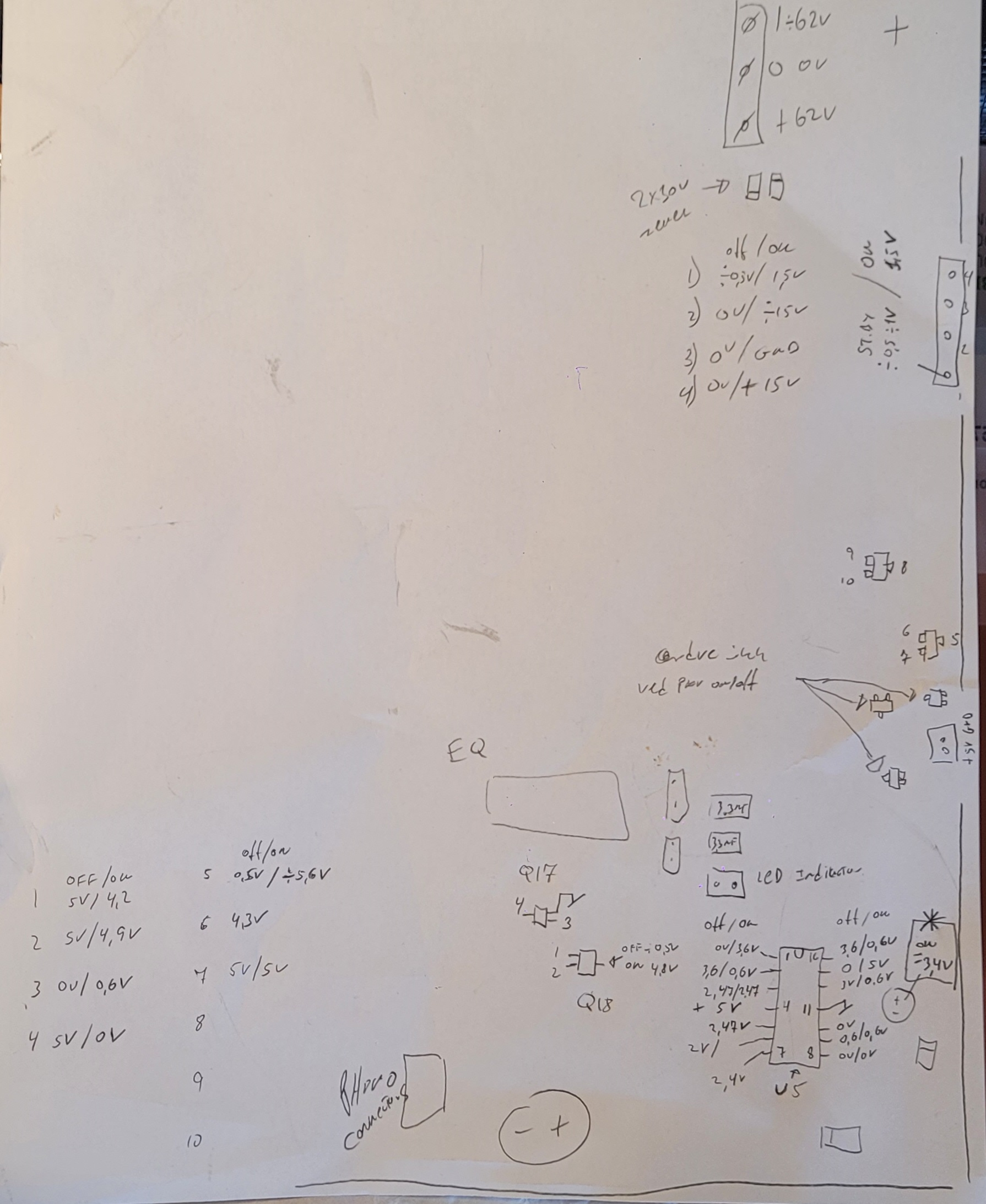
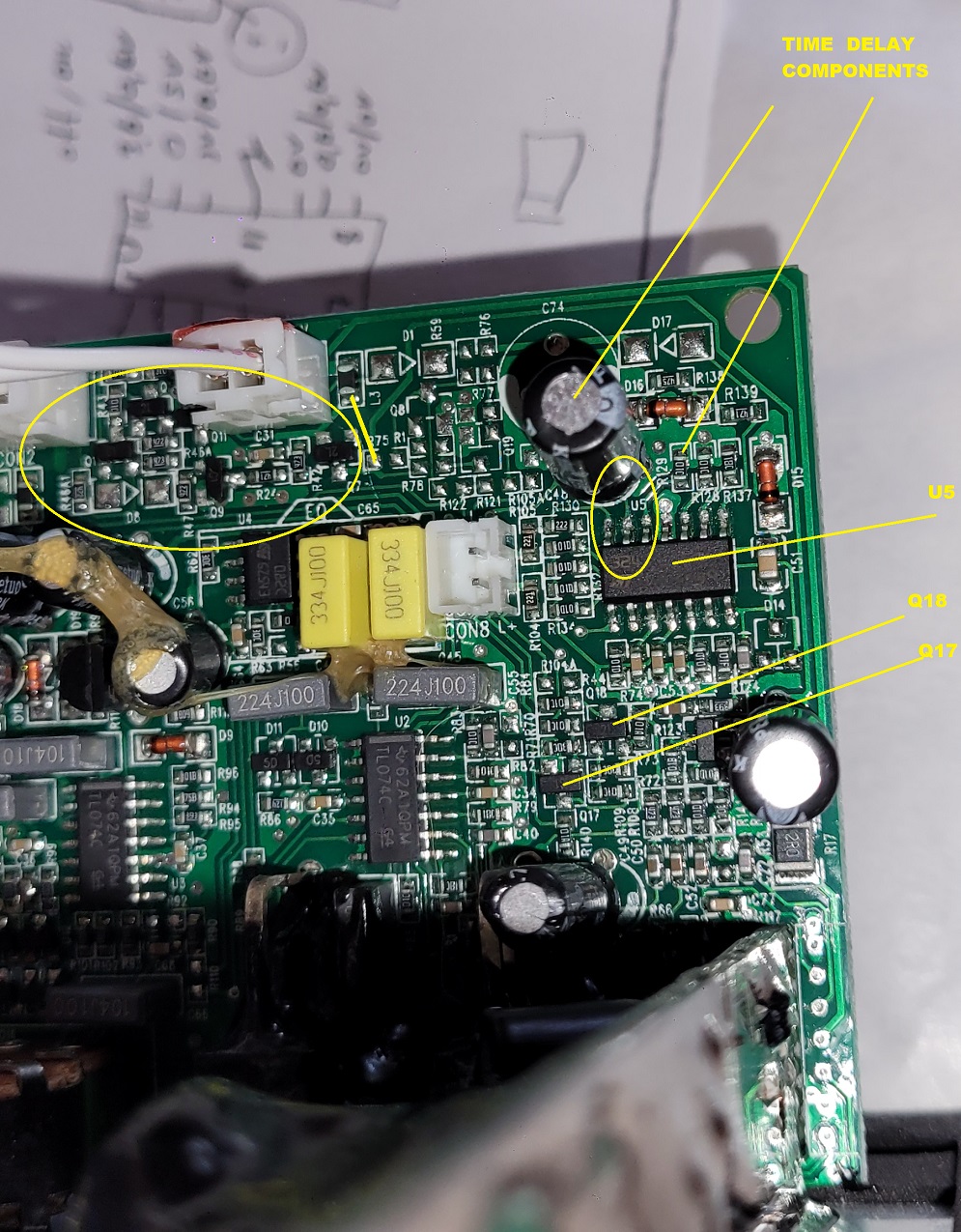
Hi BillL001 Let me try to explain. >1. In your previous post you mentioned that the C-48 capacitor (at the edge of the amp board) serves as a time delay for U5 power swith chip, No. The Solder Jumper add constand +5V st. by supply in the U5 LM324 opamp pin 4 all the time. C48 do not sit on the U5 main supply supply. C48 is only a side cap in the curcuit for the timedelay shutdown. So the size of this cap have aorund +3.6 volt across it. And is slowly drops over the ~15-20min. You can check who long time it takes before is shutdown the +/-62Volt Supplys for the amp part. >this made me wonder the following: what if we use a higher rated cap for this capacitor, from 100uF and 20V, changing it to 500uF or 10uF, and maybe 50V, so that when the power to the capacity was cut off by other part of the circuit, there is still enough power left in the capacitor to power the U5 chip, would that prolong the power to the chip so that its power will not get cut off? If this can keep the chip powered, we maybe able to take off that jumper, and just let this capacitor keep the sub going when it plays low frequencies or playing high volumes, and will not be shut off. Do you think this could be a fix for the power dopping problem? In other words, since capacitors can provide a delay in power being switched off, would increase its power saving rating be able to keep the power on long enough? The value in voltage don't change anything. There will never be above +5volt on the C48 caps. Changing the uF will only change the delay time. If you ad a 10uF its only takes 1/10 of the time before if shutsdown and if you do it 500uf it takes 5 times longer than org. 5x 15-20min before the sub close down. But if you take a volt meter and messure on C48 you will see then you add a signal to the sub it's rise in voltage, but as soon there are no signal detected the voltage drops right away to 3.6volt and will keep falling, untill a signal is again added to the signal input. Then the cap is again at full voltage, and discharge down from there when no signal added to the sub. Hope i don't confused you with this description. 2. I noticed that sometimes when I just power on the sub, the sub produces some continuous knocking or ticking sound from its cone - see below video: Ihave not seen this on my sub's. I can see on the video the cone to jumping. Could be a DC on the speaker. But i would expect its a cap problem, making the DC jump in the circuit. Don't know if you have a osc. scope, but then i would try to follow the signal way to find there the noise comes from. You can't see it with a norm. volt meter. i Osc. scope is needed to error search. But try with the caps in the EQ section first or replace all caps if you dont have access to a osc. scope. Good error Search 🙂
-
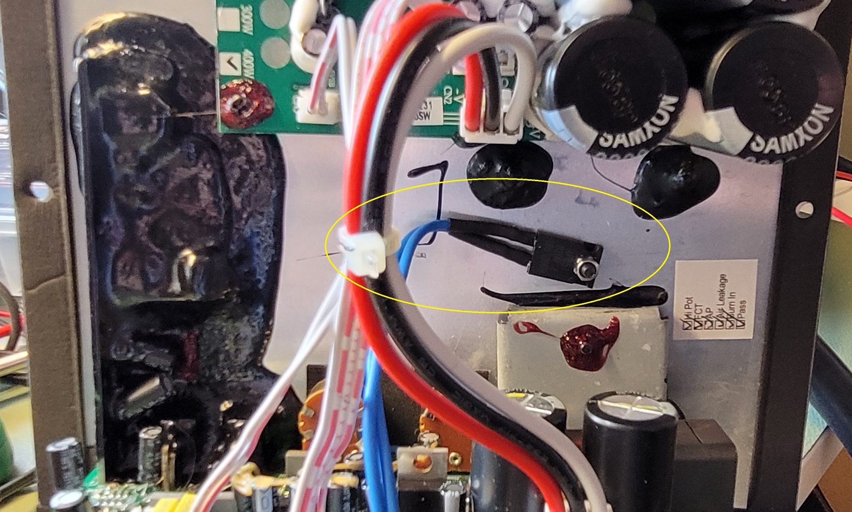
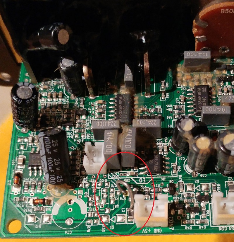
Hi BillL001 Great, you got your sub running again. 🙂 Pleased i could help you to save some $$$. 🙂 Just wanted to common on thing here: A) As you right about now knowing if the jumper would cause fire... It can't, the +5 stand by supply is really low current supply for the Op-amps only. So don't be worry about that. As i write, the only thing the jumper do, is add constant +5 volt supply for the LM324 Op-amp. I did long time test on sweep and load test on the complte PSU & Amp, and all work as it shall. Including the "Auto" sound detect start and ~15-20min Auto shutdown function. The only thing, i will say to DIY people out there: Mount the Resistor external on the ALU plate (main chassis plate) and add some wires from the external resistor to the PCB. Sorry BillL001 i don't like the copper solution you showed on the pictures. It could cause a serious short on the PCB. Better be safe than sorry. 🙂 That was the reason i did it the resistor external mounted to get any heat away from the PCB. See attached picture. Also there are some massive vibrations inside this subwoofer. I don't think the "flying" resistor solution is great on the long term use. Think it would fail over time. Because of the solder pads should hold the weight of the resistor, but also the soldering it self will be bad over time. Cause all the heat and cold all the time, the soldering it self will problerly be/get a cold soldering over time. Not so nice... So make the repair the Right way them things will last. 🙂 Some will question the external resistor, now there are wires in between, but technical the wires would only add <1 ohm to the 820ohn the resistor, nothing to say. So no problems here. 🙂 The part number for the chassis resistor: RS components :809-8718 820 ohm OR Mouse: https://eu.mouser.com/ProductDetail/ARCOL-Ohmite/AP851-820R-J-100PPM?qs=LJ1pyEEo5rYLMw1VfmR0rA%3D%3D There are many other resistor model, i just found this 820 ohm, it's was easy mount type. You can use what ever you feel. 🙂 Please feel free to ask if there are any question. 🙂

-
Did replacing the caps fix your problem? My amp is now doing the exact same thing. Hi BillL001 & Co. I have 2 pcs. SW-115 i have repaired /upgraded with new caps and a external resistor now mounted on the back side of the alu plate with a m3 Screw. see pic for 820 ohm part number RS:809-8718 for chassis mouting But one worked the other didn't. Let me explain: Sub 1: PCB marked: BFS-R115 SW-V1 20140605 On this sub I also replaced the 3 Caps and new 820ohm Resistor. Error: It would only turn on for 1 sec. then it switch off again. So I have made alot of meassurement on the working PCB. To find out who the Circuit worked. And i quickly found out the U5 - LM324 IC (lower left corner) was missing it 5 Volt supply. Came in for 1 sec. and disappeared right away. So Please See attached pictures, here is all the Off and On voltages around the signal input detection circuit from the fully working PCB (SUB 2). I used thise voltages to error search on the bad board. But could not find out why the voltage shot off again. So i have search all over the internet after a schematic but can't find anything on the 112 and 115 sub's. I came by a side where a user was made a jumper close to the St. By 5 Volt supply. So i also tryed to add this jumper to the PCB, and now it works. I checked what the Short/jumper do. It add's the +5V st.by constant to the U5 - LM324 +5v Supply Pin. Can it be a fix from Klipsch ? i really don't know, but its a working fix. I looks more on the voltages i made on the OK PCB and compared to the Bad PCB. And it looks like there are 3 transistors around the +5 st. by Voltage (2 pin connector) there have something to do with the Supply for the U5 - LM324 IC. But I can't come it closer. But the impontant thing is now the PCB now works with the Jumper fix. So i was thinking... Could be the "auto" now ain't works anymore. becaus of the Jumper Wire from the +5V st. by. (L3) To R73 pin, so the U5 - Lm324 have constant power. But that is not the case. All is working perfect now. I wanted to find out what cap. there was the for the shutdown function, and as you can see in the attach picture (handwriten one). The Cap close to pin 14-16 is the one. I checked the time before the sub. auto shutdown, and it takes 15-16 min before it shut perfect down. You can also measure on the pin 14, 15 and 16 (U5 - LM324) for this function R129 and the cap 100uF is the Tau "time". You and see as soon you add a external signal to the AMP the voltage rise right away on the cap to full +5volt. And as soon the external source is removed the voltage drops to ~3,5 volt and slowly falls down to 0.6V it shutdown. Looks like a comparator setup here, with a 0,6-0,7V as a ref. Sub 2: PCB is marked: BFS-R115 SW-V1 20160426 One of them worked perfect after the repair. But have no jumper from L3 to R73, but still works fine. Regarding a user saying it was weak below ~30 hz. I have made a measure from 50hz down to 16hz all perfect output power from the AMP output. Have over ~100-115V 'Ish peak peak amplitude. Makes sense the power supply is +/-62volt to the amp. After 16hz it fades out. So they have a filter i would say. Anything lower than 16hz don't make sense anyway. 🙂 Hope it can help others out there, to fix this. It's not a so nice constructed Circuit. Must i have seen better, in the 25+ Years i have repair stuff. Greetings Poul - Denmark