Rossi32s
-
Posts
16 -
Joined
-
Last visited
Rossi32s's Achievements
Member (2/9)
1
Reputation
-

R-110SW / R-112SW / R-115SW Repair Blog
Rossi32s replied to ngen33r's topic in Technical/Restorations
If you scroll back a through this thread there are a few lists people made. -
R-110SW / R-112SW / R-115SW Repair Blog
Rossi32s replied to ngen33r's topic in Technical/Restorations
Recap it, especially the 6 capacitors closest to the resistor. -
R-110SW / R-112SW / R-115SW Repair Blog
Rossi32s replied to ngen33r's topic in Technical/Restorations
www.saoelectronics.com -
R-110SW / R-112SW / R-115SW Repair Blog
Rossi32s replied to ngen33r's topic in Technical/Restorations
This is not the thread for the unit you are working on. Nobody here has the plate amp you are working on. -
R-110SW / R-112SW / R-115SW Repair Blog
Rossi32s replied to ngen33r's topic in Technical/Restorations

-
R-110SW / R-112SW / R-115SW Repair Blog
Rossi32s replied to ngen33r's topic in Technical/Restorations
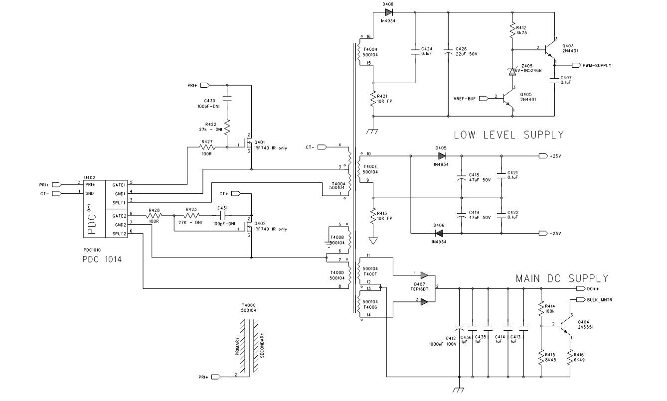
This schematic is about the closest i can get you to that unit. May want to start a new thread somewhere... this is really getting off topic for this Klipsch thread.
-
R-110SW / R-112SW / R-115SW Repair Blog
Rossi32s replied to ngen33r's topic in Technical/Restorations
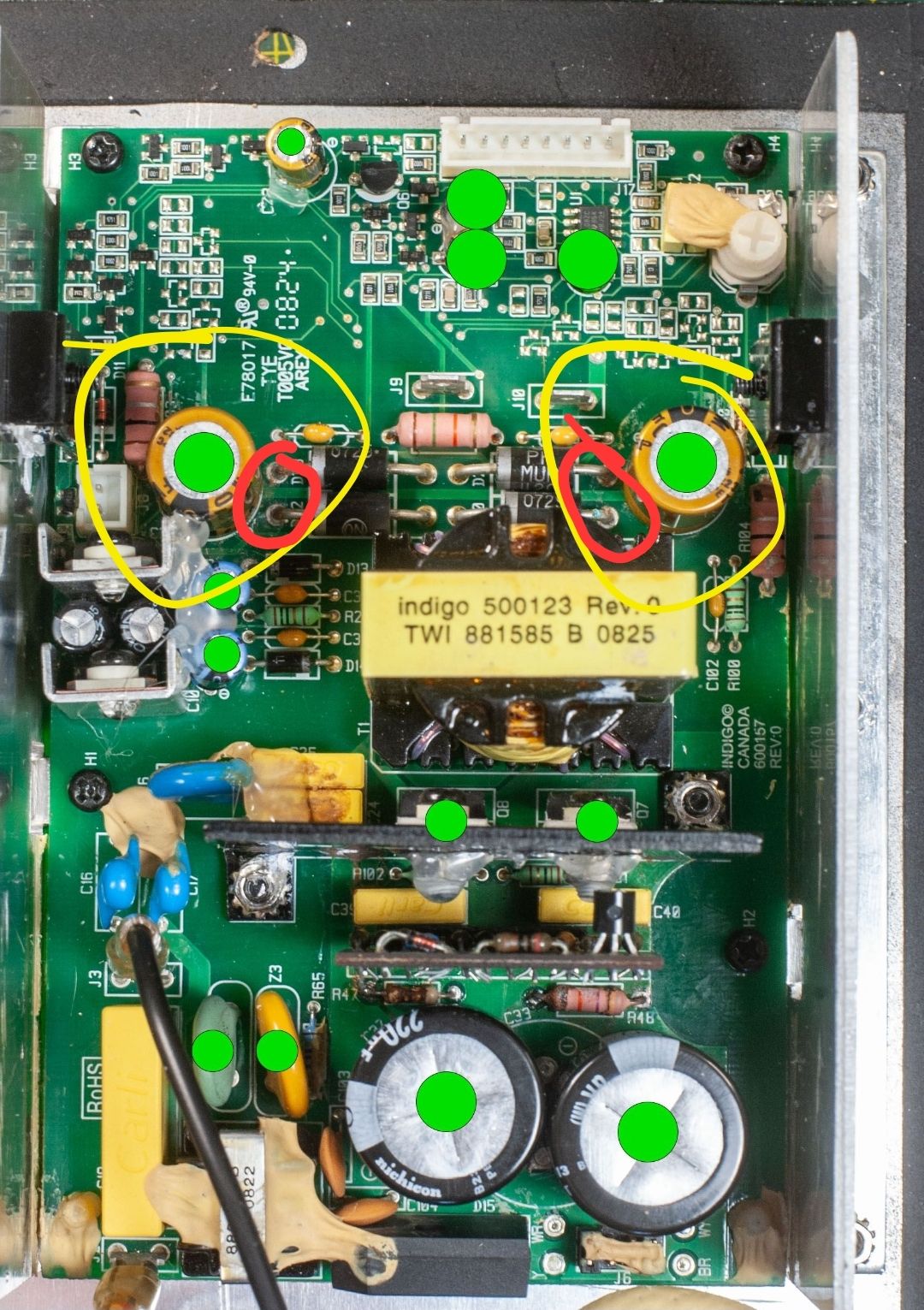
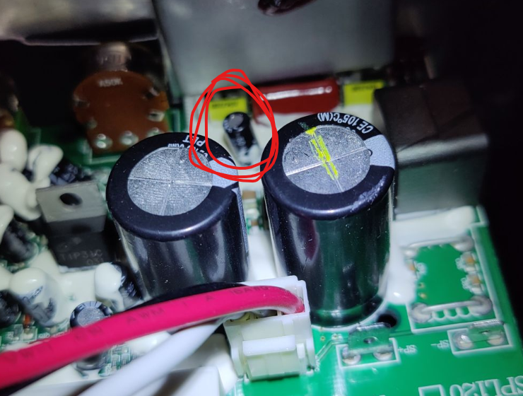
What is your DC voltage across the 2 points circled in red? Without seeing the bottom of the board I am going to assume that is the DC side of the rectified AC coming off of the switching transformer.
-
R-110SW / R-112SW / R-115SW Repair Blog
Rossi32s replied to ngen33r's topic in Technical/Restorations
Doesn't exist.. if you scroll through this thread, some people have posted some similar ones. Best off posting questions and symptoms and I or someone else will guide you. I've repaired hundreds of these. -
R-110SW / R-112SW / R-115SW Repair Blog
Rossi32s replied to ngen33r's topic in Technical/Restorations
You won't get a voltage at the speaker outputs without a signal in.. you need to measure your drive voltages coming from the power board. I'm going to guess that amp is about 100w.. so you're looking for + & - voltages coming off the power board around +25-30v & -25-30v. Once you have that, you can focus on the signal flow. The ribbon cable should have some writing on each wire too, they don't look thick enough to carry the 4-5A at 25v needed for the amp board. Where does J9&J10 go? I'd also recap the entire secondary of the PS board. I've never worked on that exact model but you should have the 25v + and - with respect to power ground and likely a 5v for the audio signal circuit and possibly 3v. Ribbon cable likely also has a standby output to tell the power board to go into standby.. if it's stuck in standby, should still get your 25v long enough to charge the 2 caps in the secondary to get a close measurement to verify switching is working(until they drain, about 10 seconds or so). Also verify your voltage on the primary caps.. if you are on a 120v system they will be around 160v DC.. if you are on 220.. around 310v DC. Fair warning, on a 220v system.. those caps will kick you pretty good.. don't slip with the probe either.. use the dim bulb until you feel it's sorted out. -
R-110SW / R-112SW / R-115SW Repair Blog
Rossi32s replied to ngen33r's topic in Technical/Restorations
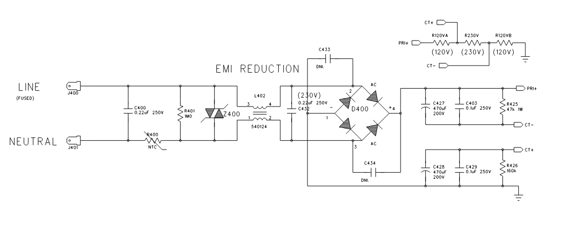
Wire the hot or netural of main power in, in series with a 100w incandescent bulb. If there is a short, the bulb will light instead of frying your power board. LED bulb will not work. -
R-110SW / R-112SW / R-115SW Repair Blog
Rossi32s replied to ngen33r's topic in Technical/Restorations
Your resistors are good. If you are blowing fuses, check the switching circuit for a short.. -
R-110SW / R-112SW / R-115SW Repair Blog
Rossi32s replied to ngen33r's topic in Technical/Restorations
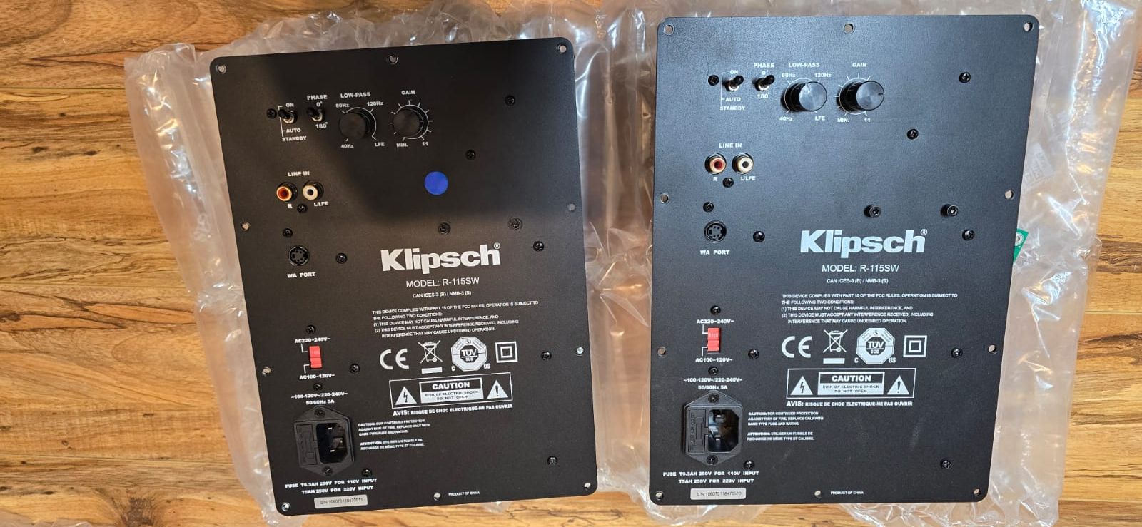
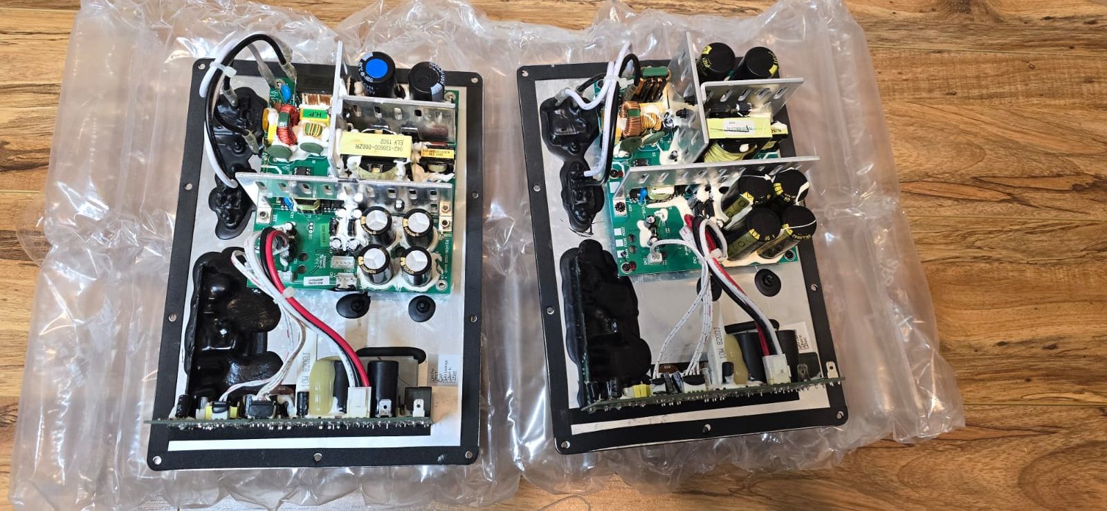
Does anyone need these? $40 each/$80 for both, delivered anywhere in the US. I can assure you the SMPS boards are bad on both and the amp boards likely only need the caps around the resistor replaced(we would recap the whole thing if we were repairing them). The amp boards have not been worked on; The SMPS boards were likely thrown on the Huntron to determine the failure, and with all the white glue on the power supplies, we don't replace components covered in the glue. We are getting so many of these in that we have no desire to fix these excess units and sell them working. These come in from customers only wanting one fixed but send 2 for a discount on their repair.
-
R-110SW / R-112SW / R-115SW Repair Blog
Rossi32s replied to ngen33r's topic in Technical/Restorations
Change the one circled in red.. 22uf 50v
-
R-110SW / R-112SW / R-115SW Repair Blog
Rossi32s replied to ngen33r's topic in Technical/Restorations
Replace the 22uf 50v capacitor that is in the top left edge of your picture; you can see just the very edge of it in black. -
R-110SW / R-112SW / R-115SW Repair Blog
Rossi32s replied to ngen33r's topic in Technical/Restorations
I do... google the company name in my profile picture