Xxerby
-
Posts
1 -
Joined
-
Last visited
Xxerby's Achievements
Newbie (1/9)
0
Reputation
-
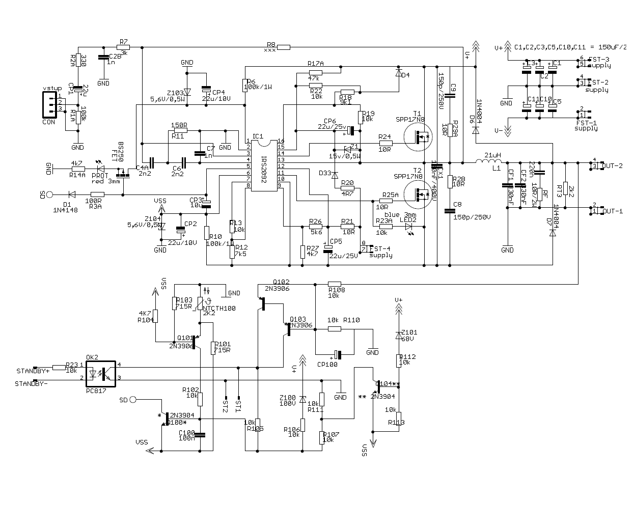
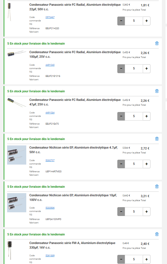
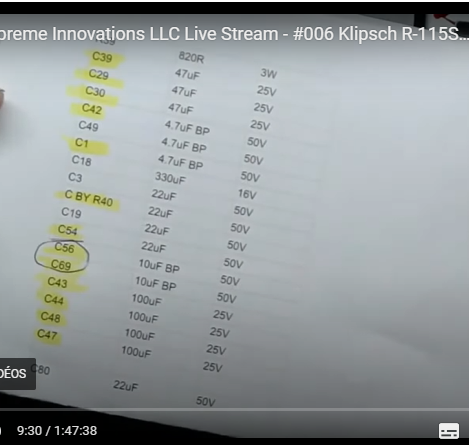
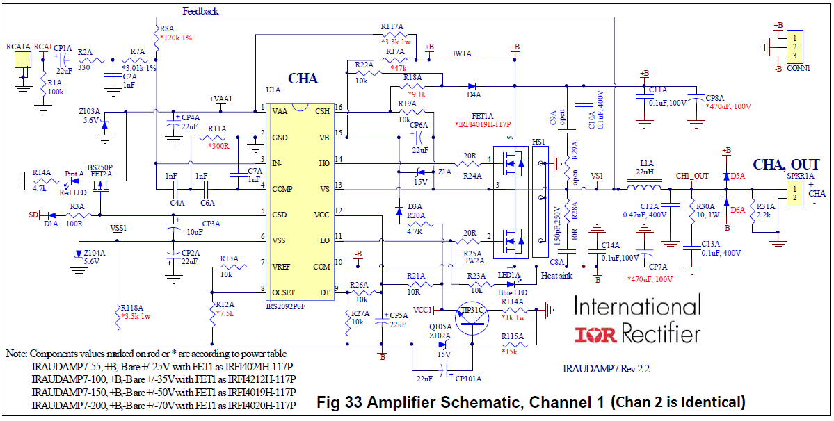
Hello everyone, Excuse my translation, I am French, more precisely from Montpellier. I just finished repairing my 115SW after almost 50 hours. I searched all the blogs, forums, videos that could allow me to fix it. I had at my disposal two HS amps. One of the two was used to do some retro engineering. I wanted to thank you for the valuable information on this particular blog. I wanted to share with you all the information I have gathered. Here is a quick description of my problem: LED indicator on, no sound output. After opening, I noticed that the amp had already been repaired or rather that the previous owner had tried. I checked all the power supplies, various filters and preamp. The power board is functional The power resistance and the person who tried to repair the amp destroyed several tracks and component. After repairing and cleaning all the damage, I replaced all the capacitors as recommended as well as the power resistor with a ceramic resistor of 820R 10W. After making all these changes, injecting a sinusoidal signal in 20 Hz input using a mobile app, I could see with an oscilloscope a continuous component on the output and peaks at +63V intermittently. Using the documentation and the application note I checked all the voltages. At the end of the comparator (COMP) I had a good frequency square signal, so the problem came from the corner. Both VREF and OCSET resistors are out of service and the IRS has burned on one side. The symptom I had was overcurrent protection that was characterized by a triangular signal on the CSD pin. The amp goes into error and the capacitor discharges. The amp restarts and the voltage rises gradually and this indefinitely, which creates a triangular signal. CSD is easily visible on the via located in front of the CON/-15V/GND/+15V connector next to R50. (AN P7/P8) Here is the summary of everything I had to fix: - PWM IC Replacement (IRS2092) - Reconstruction of two runways (between Q15 and Q3 and between RA4 and RA5) - Replacement of a bipolar capacitor (C10) - Bipolar Replacement (Q15) - Replacement of all capacitors and power resistor - Replacement of two SMD resistors near IRS (R08 and R11) I attach several images and files that can help. The diagrams are not necessarily complete but can help. These are the schematics I mad : https://ibb.co/H4x2WyQ https://ibb.co/5XQhkWL https://ibb.co/T0Gh9Bx I hope this information will help you in your repair, good luck. https://320volt.com/en/400w-claas-d-subwoofer-amplifier-circuit-irs2092/ (most faithful schematic) https://pdf1.alldatasheet.fr/datasheet-pdf/view/25416/STMICROELECTRONICS/TL082C.html (TL082C 2OP -> Phase inverter) https://pdf1.alldatasheet.fr/datasheet-pdf/view/22753/STMICROELECTRONICS/LM324.html (LM324 4 AOP) https://pdf1.alldatasheet.fr/datasheet-pdf/view/25399/STMICROELECTRONICS/TL074C.html (TL074C 4 AOP) https://www.infineon.com/dgdl/irs2092.pdf?fileId=5546d462533600a401535675f1be2790 (IRS DOC) https://www.infineon.com/dgdl/an-1138.pdf?fileId=5546d462533600a40153559a077610d1 (IRS AN)