Roamin
-
Posts
4 -
Joined
-
Last visited
Roamin's Achievements
Newbie (1/9)
1
Reputation
-
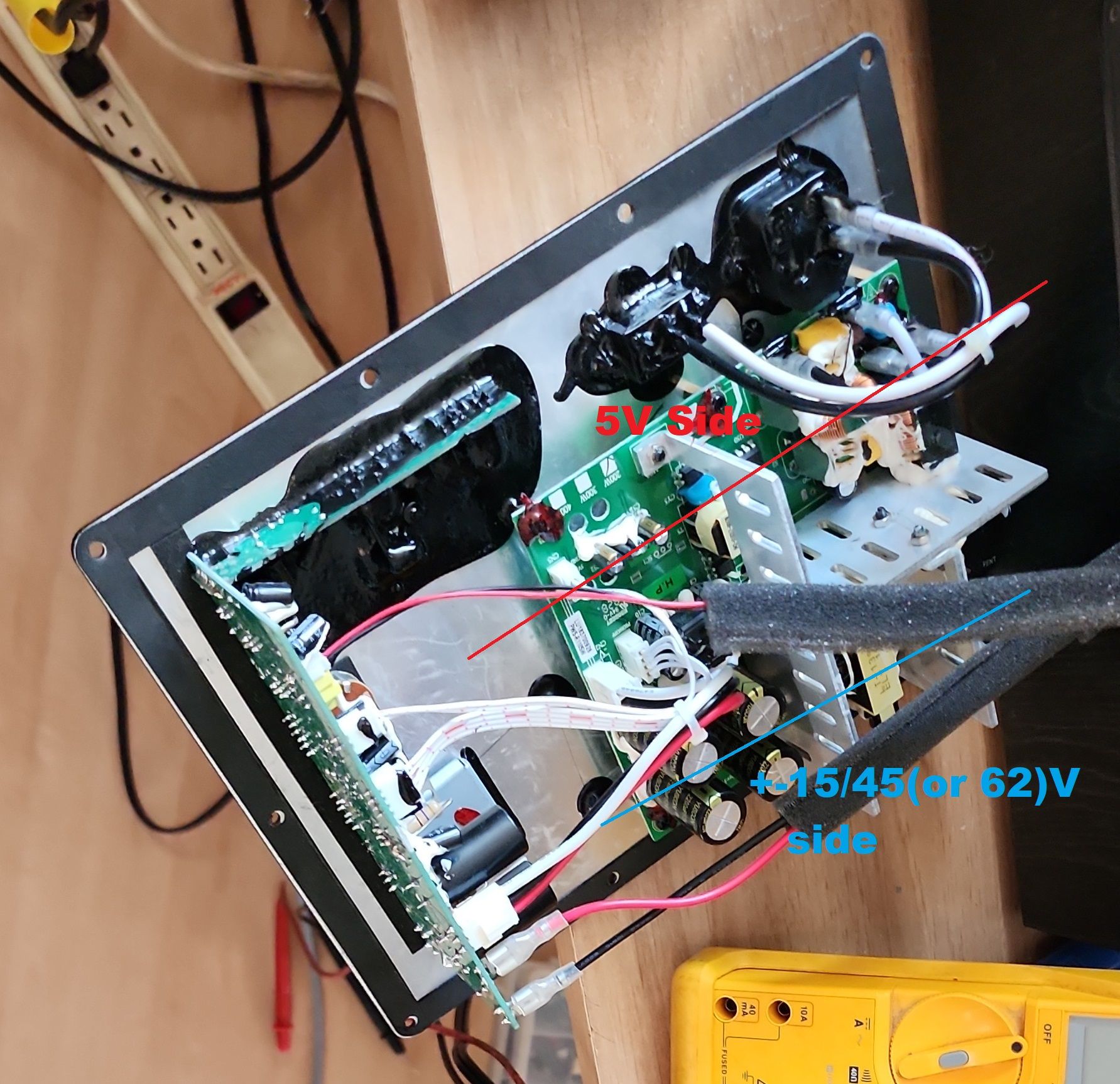
If you don't have those voltages , I suggest you unplug both these connectors on the amplifier side, and plug the power to your sub. Are the voltages there in the disconnected connectors ? On the power supply itself? If those voltages aren't present then the problem definitely starts in the PSU (power supply unit). Disconnecting the cables from the amp would ensure that it isn't the amplifier itself pulling down the voltages, but I kinda doubt it anyways. I did not need to check anything on my power supply and don't have any pictures of it , but if you take good pictures of yours I can always guide you through different tests to do on it. The PSU didn't really seem to be that complicated so finding the fault should be fairly easy. One thing I liked about the design of the amp is that it uses easy to find components and doesn't rely on parts you can only find in Asia and I'm pretty sure it's the same for the PSU. Edit : Re-reading your past posts , I grasp that you already did disconnect the amplifier to check the voltages. Get some close up , top down pictures of the PSU , even better would be pictures of the solder side as well and I'll try to help you find the fault. I have but 1 picture of my power supplies but I can't see anything at all on them from this distance, but with the size of the transformers it's safe to say it's kinda separated in 2 sides , the 5v and the higher voltages on the other side..

-
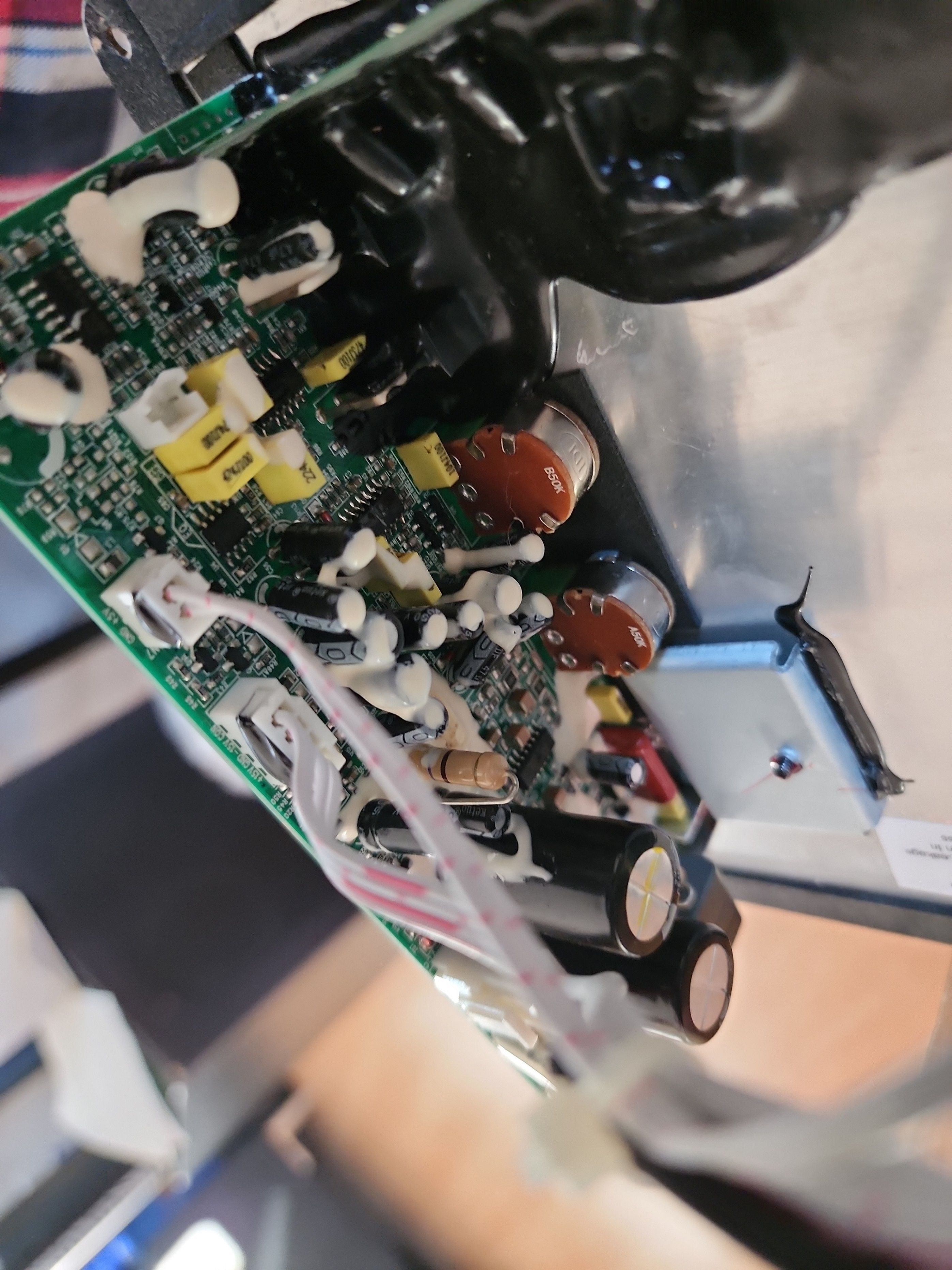
I wouldn't worry about this capacitor for now. How does the one just above, C85 , react? Does it also beep? Those cap are right in the vicinity of the 2 jumpers that are in place of coils and it's very possible that they are in parallel with those jumpers (which are labelled as coils on the board) and could have been to suppress interference around those coils.. The very first thing to focus on in any reparation is always the voltage. A multimeter that can read DC voltage up to around 100v is all you really need in order to measure voltage in this amplifier and if you are stable enough when handling the probes, there shouldn't be any risks at all. One of the first thing I was thought in school when I learned electronics was that when you are about to measure something with your probes , you always place at least 1 finger from each hands or part of the hand on a stable surface and never have your hands just floating around. It stabilizes your hands and the probes and you have less chances of slipping and shorting something with the probes. The voltages on this board are quite easy to measure if your probes are thin enough to simply insert them in the pins on the side where the wires come into the sockets. The cable that has 2 wires is labeled with 5v and GND. Keeping your black probe on the GND pin you can measure all the voltages with the red probe. You can measure the 5v on that connector , the +15/-15 on the connector with 4 wires, and the -42/+42(or 62 volts depending on the board) from the thicker wired 3 pin connector. You can also measure the voltage on the big resistor I mentioned before and see if it fluctuates from -0.4 to -4 volts. If it fluctuates with every pop , the irs2092 is most likely acting up.. You might need help changing that part though because it is not easy to do since it has small pins and it is in an awkward location.. But if you pinpoint the problem you can probably have someone change that chip (and maybe some capacitors too) for you.
-
Measure the voltage on the big resistor that is connected to the power transistor in the middle of the board (in my case it's a TIP31C). Does it change every time your amp pops? If so the IRS2092 is most likely to blame.. The short circuit protection kicks in and then resets , causing the woofer to pop constantly. The part is 5$ CAD from Digikey.. search for IRS2092STRPBFCT-ND on their site. You might want to change a few caps too, it can't hurt. About that beep on your capacitor, does it beep constantly or does it stop after a moment? Does it beep if you reverse the probes ? If it stops after a moment or doesn't beep with probes reversed I wouldn't worry about it. Are the voltages present on the connectors? 5V ? +-15v +-62 (on my specific board it's +-45v)? If all voltages are there I really wouldn't worry about that capacitor, it's common to have capacitors on power lines making the meter beep for a short moment , or sometimes with the probes in one way but not the other , depending on the circuit configuration.. The caps on my board are fine, only the IRS2092 needed to be changed. On my specific board , for a SPL-100 sub , the resistor doesn't get hot at all and no parts around it were worn or damaged.
-
Just joined this forum to share my experience. I have 2 SPL-100 subwoofers that share a very similar amplifier. Part number is : PD-BFS-R110SW-V1 . Manufactured 20180522. The subs have a 200w power supply. My issue started just a few months out of warranty, I contacted Klipsch but I was told they don't do international warranty (I'm in Canada) and directed me to a local repair center (local , but still kinda far). My issue was that every few minutes I would hear a "Pop" coming from the sub. It took me a while to even understand that pop was coming from my sub, and probably only did when it started doing it very frequently.. I unplugged the sub for a while since I have 2 but I got lazy and I never sent the amp for repair at the repair shop.. Eventually I plugged it back in and by then the "Pop" wasn't there anymore.. I figured I got lucky and the issue went away. Few days ago I wanted to add more bass so I went for the gain on both subs and realized , the sub wasn't working at all! Even though the green power light was on, it was dead. So I'm guessing I went for at least a year with 1 sub down and didn't even notice.. So began the search to see if anyone had repaired this thing before and I ended up in this thread. Not having done any research at all on this problem before I read through the entire thread. Most people here speak of overheating resistors, cooked capacitors, dead transistor but my board had nothing of the sorts. All the bigger wattage resistors were all clean , no busted caps, nothing. Even the main transistor is different in my build , it's a simple TIP31C. The resistor driving it is a 470 ohms, which is intact. Having 2 identical subs I decided to open the second one and start comparing stuff. I quickly found that in the working one , the resistor had -4 volts on it but on the dead sub that voltage was at -0.492 volts. At one point , by accident I noticed that if I powered on the amp it would work for about 3 seconds and the voltage would raise to -0.492 volts (I say raise because its a negative voltage). I tested the amp by putting my finger on the cable plugged into the left channel just to hear a hum caused by noise. After 3 seconds it would die and would only work if I waited about 10 minutes with it powered off. Since this was constant, I figured it's not a passive component like a resistor or transistor because those usually work or don't but ever rarely are they intermittent like this, especially if they have no signs of damage. So I decided to go take a look at the datasheet for the IRS2092 to see if it has any type of protection , which is frequent in ICs and sure enough it has an over-current protection. It was then I realized that the "Pop" sound I had been hearing all this time was caused by this IC, constantly cutting off the power causing the "Pop" and then resetting back to normal operation right away. Since over-current should come from the MOSFET (in my case , my board uses a dual MOSTFET instead of 2 independent parts, part # IRFI4019HG) the easiest thing to try quickly was to move the MOSTFET from one amp to the other and so I swapped both parts. Unfortunately the dead amp remained dead and actually it stopped turning on for 3 seconds, but the working one still worked with the swapped MOSFET, telling me both parts are working. I didn't want to swap the IRC2092 from one amp to the other because it's somewhat tough to access and removing it to re-install it somewhere else might not be the best thing. I started looking around if this component had a high failure rate and for any other information I could gather and found some on the DIYaudio forums. While the failure rate doesn't seem astronomical on this part, it's a very common part , used a lot in the DIYers community and I came across a post by "nigelwright7557" that said, the IRS2092 is fussy , large MOSFET gate capacitance will trigger the overload protection, if the MOSFETs go it usually takes the IRC2092 with it too so change them both. So I went on Digikey, ordered both the IRS2092, the IRFI4019HG , and also all capacitors on the board just in case (the list is exactly the same as the picture in Xxerby's post). I figured , can't hurt to have to capacitors in case. Got the parts the following day and installed them both (I didn't change any capacitors at all) and voilà! The subwoofer lives! I didn't need to change the MOSFET because the original one of this board is now in the amp that worked and this board had the one from the working amp after I had swapped them.. but I figured may as well put both parts , since they only were 5$ CAD each. A quick explanation as to why the transistor (TIP31c on my board) turns off when the protection kicks in is that there is a pin, CSD, as mentionned by Xxerby that is part of the auto-protection circuit. This pin feeds the power for the transistor and when the protection kicks in , even though the transistor is still closed (voltage on it's base is always present) there is no longer power on it's collector and the IRS2092 is driven by this power , through the emitter. (Thanks @Xxerby for your outlines of the connections on your board, it helped me figure this part out since my board is full of white silicone and not glue like the boards in this thread). In the end the IRS2092 failed and kept triggering the auto-protection , even though there was no over-current situation, causing a "Pop" every time the chip would reset... The end. Sorry for the book, but hopefully it helps others in the future.