mmmboost
-
Posts
6 -
Joined
-
Last visited
mmmboost's Achievements
Newbie (1/9)
0
Reputation
-
R-110SW / R-112SW / R-115SW Repair Blog
mmmboost replied to ngen33r's topic in Technical/Restorations
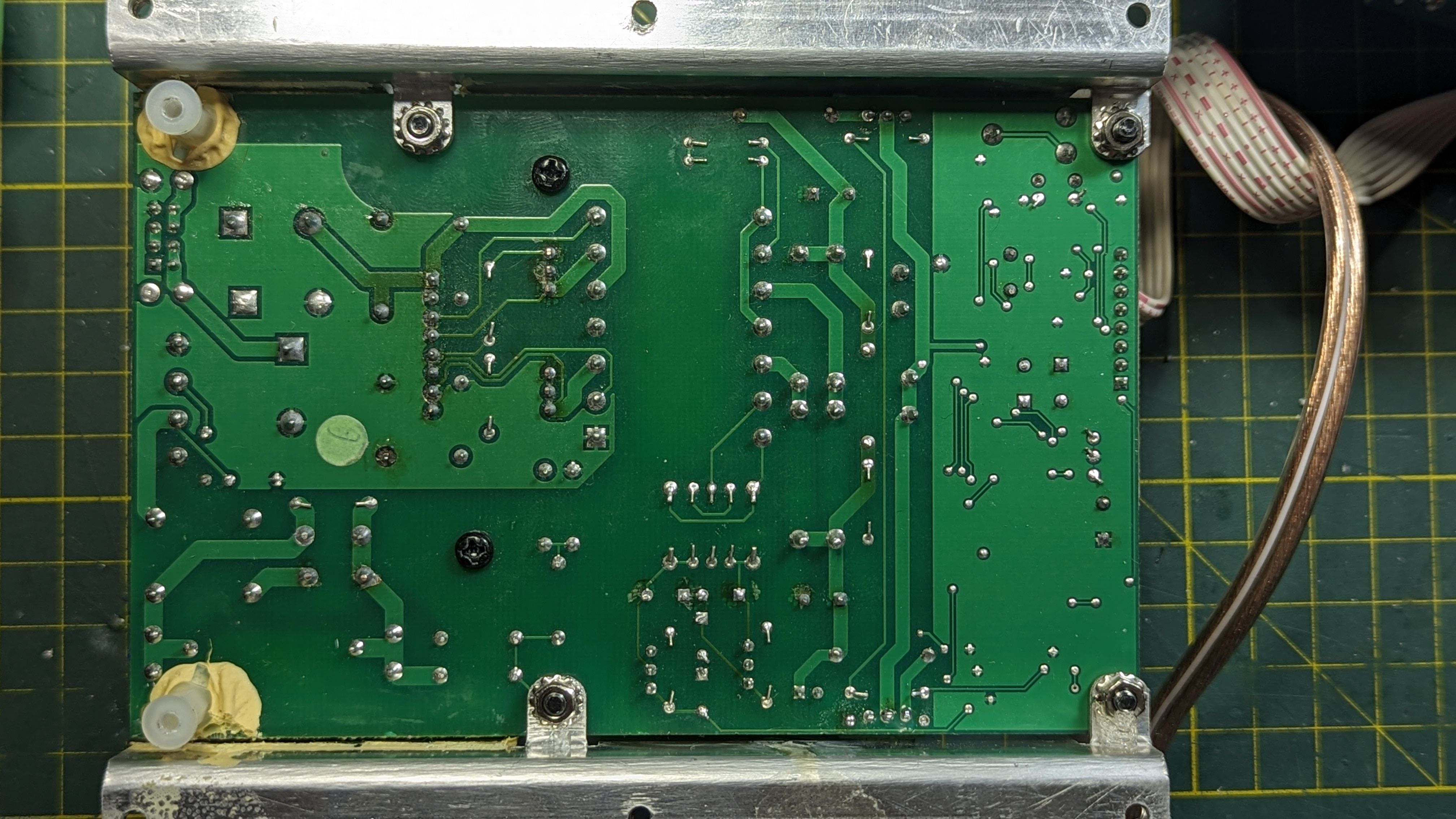
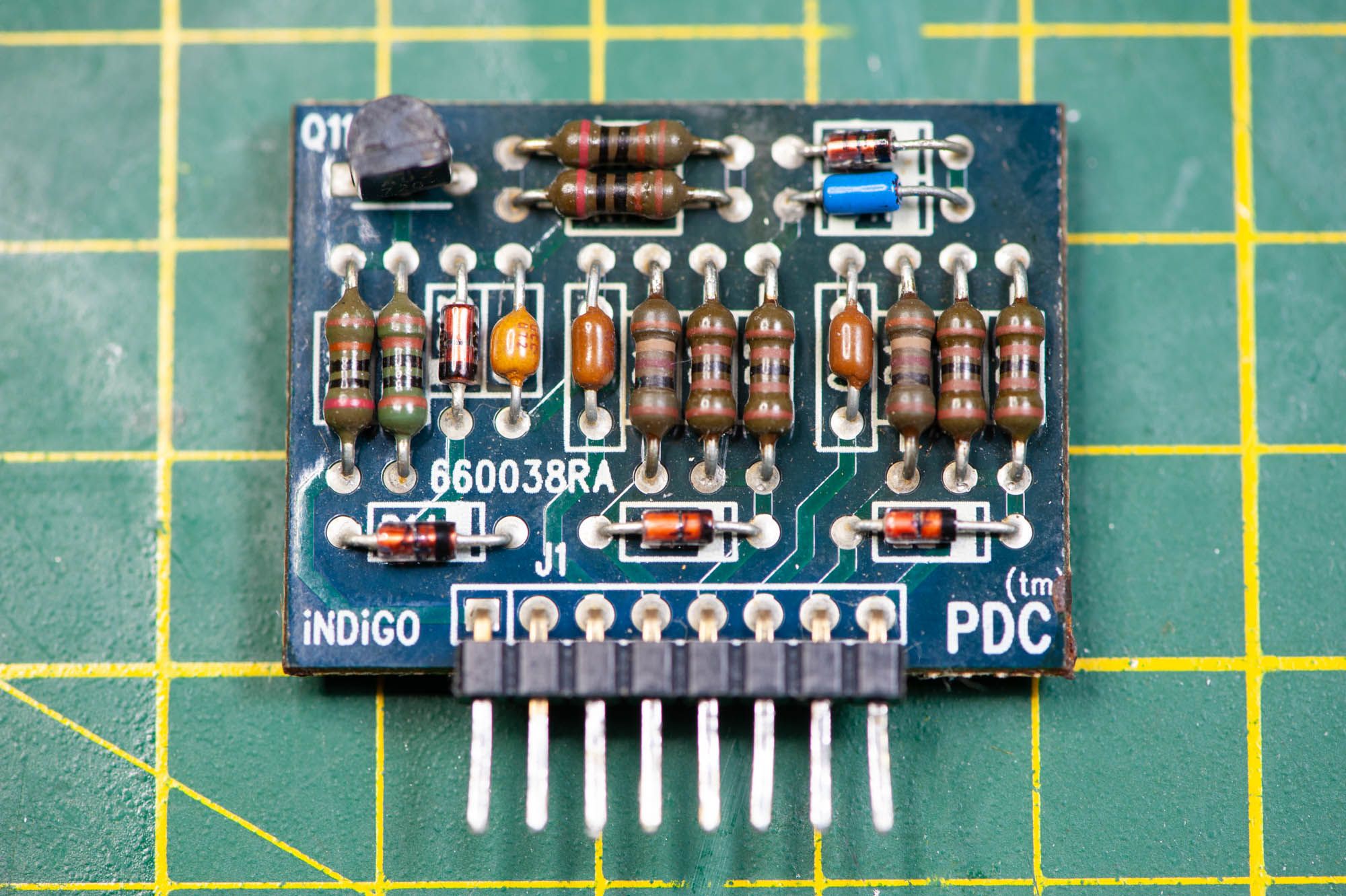
I've got..... 0V (sad trombone). It seems like things are getting stopped up at the PDC board. Here's a shot of the bottom of the board. AC input on the LHS
-
R-110SW / R-112SW / R-115SW Repair Blog
mmmboost replied to ngen33r's topic in Technical/Restorations
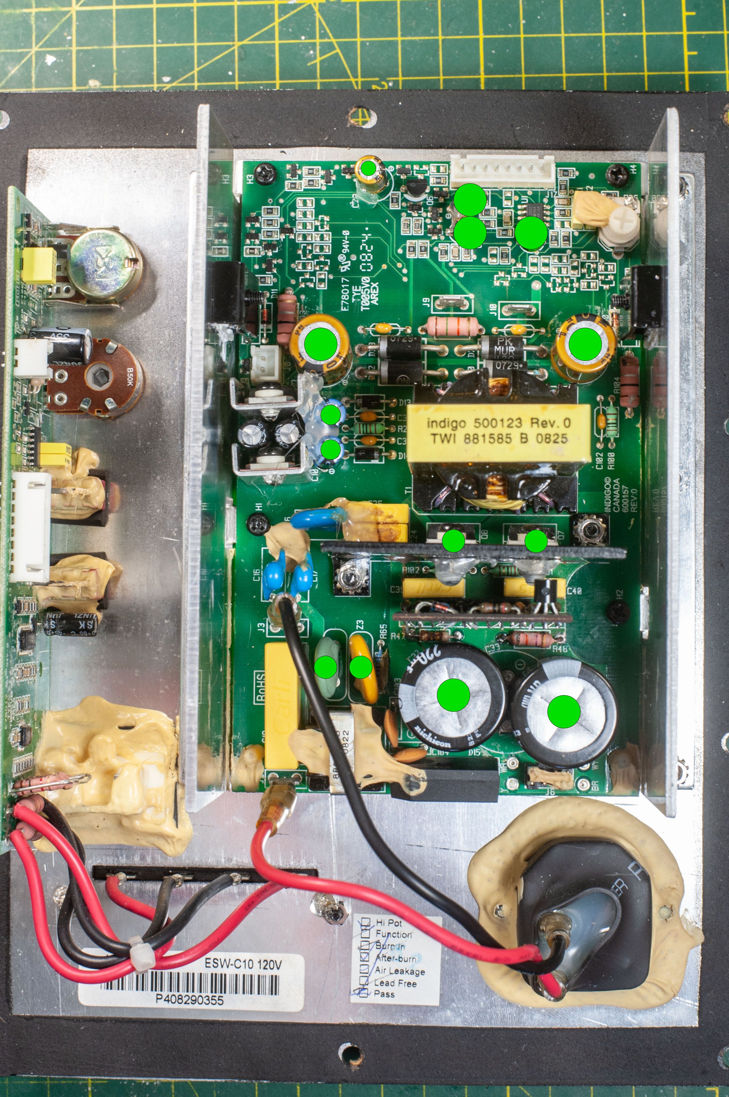
You know, I knew I shouldn't be seeing anything with no signal, but it was late and I guess I wasn't thinking straight. My board is slightly different than the Klipsch amps I see in this forum, but they share a lot of commonalities. I guess it's not obvious where I should be trying to see where I've got voltage A or voltage B, etc. To answer a few of your wonderings, the amp is rated for 150W RMS, 300W Peak. The Ribbon cable is 26 AWG so it's probably not going to be hauling a lot of current. J9 and J10 are the driver outputs. I have 166V on both of the 220uF caps. I don't seem to be getting much action from anything beyond the PDC though. I've attached a new photo of all of the components that I have replaced. Should I be changing the two caps on the daughter board with the switches and the pots? There is a 22uF and a 100uF. They both measure out to be well within tolerance.
-
R-110SW / R-112SW / R-115SW Repair Blog
mmmboost replied to ngen33r's topic in Technical/Restorations
Well I got everything all back together and fired up with a 60W bulb (only 100 I had was a halogen). The bulb came on dimly for an instant while the caps were charging and then went out again, so things are good there. However, I wasn't able to replace the DIAC on the PDC board because Amazon delayed the shipment (and I'm guessing it's going to get cancelled). I'm not really getting a voltage reading at the speaker outputs and the PDC board is getting quite warm, so I'm thinking I'm going to have to replace the DIAC......if I can ever find one in Canada. -
R-110SW / R-112SW / R-115SW Repair Blog
mmmboost replied to ngen33r's topic in Technical/Restorations
Frig.....that's genius. Such a simple solution. Now to go digging in the basement to try and find an incandescent bulb. Haha. -
R-110SW / R-112SW / R-115SW Repair Blog
mmmboost replied to ngen33r's topic in Technical/Restorations
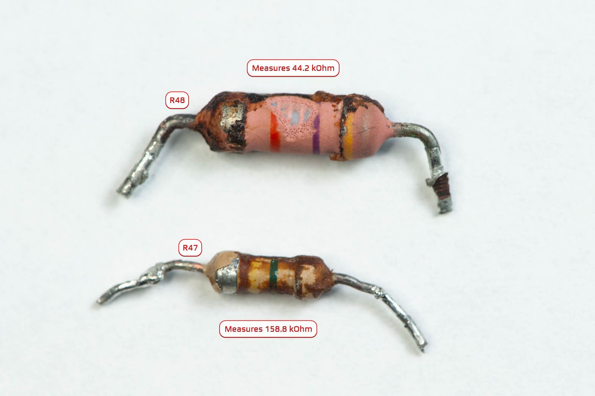
Thanks very much. Just to be sure, I ordered a new 47 kOhm and a 150+160 kOhm resistor. All my parts should be here tomorrow, so I'm hoping I can get this thing back up and running tomorrow. I don't have a scope or a current-limited AC power supply (only DC).... so what's the best approach for testing to see if this is going to work again. The last thing I want is to cook the new MOSFETS or Caps. -
R-110SW / R-112SW / R-115SW Repair Blog
mmmboost replied to ngen33r's topic in Technical/Restorations
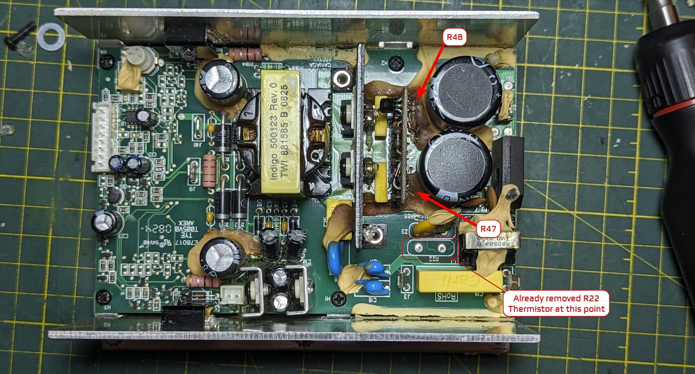
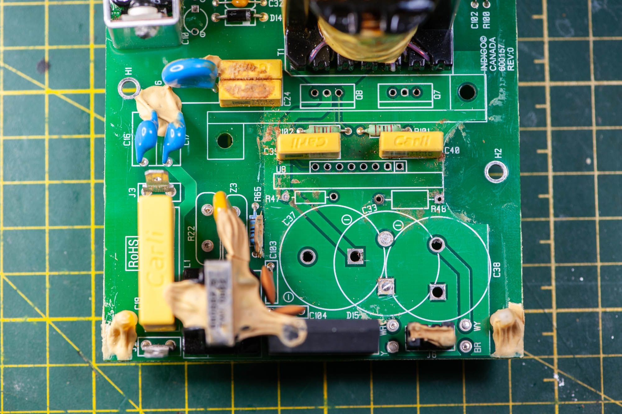
Hey guys, new on here but I've found this thread INCREDIBLY helpful. Thank you so much for all of the detailed information on here. I'm working on an amp that is also made by Indigo, but it's a little different from the usual units around here. I'm really hoping to get some help with some component ID's. The subwoofer is an Energy ESW-C10. Purchased used and was stated to be working, but when I got it home it ended up being dead, so I replace the fuse. Blew that one too. Took the amp out and immediately saw the corrosion from the glue, a bulging top on one of the 220uF 200V caps, and thermistor with a chunk blown out of it. Here's the issue, I need help identifying the two resistors that were baked under the crispy glue by the PDC board. I tried to clean off as much glue as possible to be able to read the color codes, but the paint was damaged as well. I'm hoping someone has some experience with this amplifier or can help me identify the resistors.