Jim E
-
Posts
129 -
Joined
-
Last visited
Content Type
Forums
Events
Gallery
Everything posted by Jim E
-
I have been installing another screening room at work. It doesn't leave much time for recreational fun and hobbies.
-
---------------- On 7/24/2005 9:59:41 PM Tubes, Horns, and Buds wrote: I am going to listen to these locally on Friday. I was going after a pair of cornwalls and the seller offered the Cornwalls but told me I should listen to these first. He said that he preferred "100 to 1" over his cornwalls. I told him that if that was in fact true, I need to hear these. Any opinions on this model vs. heritage speakers? Also, does anyone have a good idea what fair market value? The pair I am going to hear is "in pristine condition, about 20 years old, finished in walnut veneer." Thanks-Keith ---------------- Keith, The Altec Model 14's are pretty good. These are two-way speakers and look much like the Altec Model 19. Most believe they sound a little forward but then again this is one of the reasons we like horns. The high frequency driver is a 902-8A or B version with a small CD horn. A fair price would be 400 to 800 dollars depending on their condition. I think these went out of production around 1983. Usually the foam surround on the low frequency driver has rotted so it is quite likely they will need to be re-foamed. Parts Express has a good replacement 20 dollar foam kit for the driver. Jim Take a listen. They are good looking cabinets and are somewhat smaller than the Corns.
-
Chris, OK Jim
-
Chris (popbumper), I'm quite willing to share the cad file(s) with you. I would need to know what file type you would need as I am not aware of any cam programs that translate acad files directly. I have the three port version layed out in Autocad Mechanical 3-D or 2-D dwg files. I could also supply you with dxf format files. DXF might be the best bet as it was intended to be a universal file exchange format. If nothing else I could generate a high res PDF file. If it is of any interest, I have drawn the La Scala and the Belle Klipsch in cad as well. I am personally not interested in building a Cornwall but a Belle would work. Jim
-
What I said was contact cement is not the right stuff for veneer. Use what you want but PVA glue is best for veneers. Before modern adhesives became available, hyde glue was the standard for centuries. Contact cement is better suited for applying laminates such as formica. I apologize for putting my 2C in. There was no intent to critique your project in a negative way. I admire your effort and was only offering a little advise from thirty five years of experiance. I hope it works out for you.
-
---------------- On 5/3/2005 11:33:37 PM cueman wrote: I thought veneer would be more stable myself. This is raw veneer, with no backing on it. I used contact cement and was very surprised that this happened. Luckily, I have just enough veneer to redo this one. I think I will fill the gaps and just re-veneer right over the top. Scraping this stuff off is not something I want to do. I will definitely post pics of the finished product. Should be another week or so. ---------------- Cueman, That bubinga is hard to beat in the looks department. With the right clear finish it will look three dimensional. Please don't use any stain on this beautuful wood. It's not the raw veneer. Contact cement is not the right stuff for veneer. Especially the water based types. Even the original contact cement "creeps". It is too bad because it looks like you did everything else right. If you want the new veneer to work you will unfortunately have to strip off all the old veneer and remove all traces of the contact cement. One word of warning. Some African and South American wood species should not be sanded without a respirator so be safe and wear a mask.
-
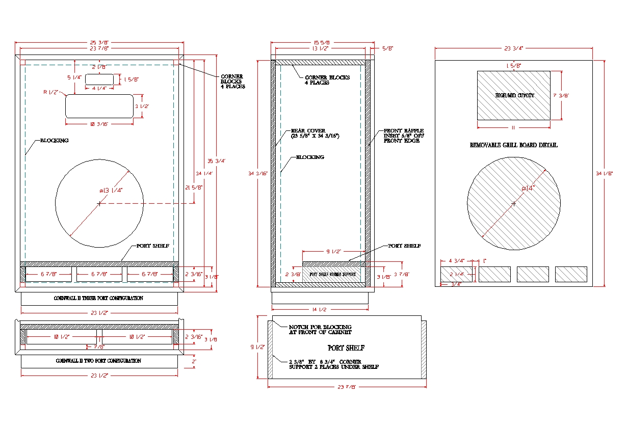
In the drawing, the front baffle or "motorboard" is 1/8" smaller on all four sides to acomodate the thick cane type grillcloth. If other materials are being used for the grillcloth, I think the baffle should be sized accordingly. Taking all of this in account, it looks like all versions of the Cornwalls have about the same exact measurements so... either type of cabinet can be built with the same dimensions. Just substitute the baffle for the verticals. If you are building two, just turn one of the baffles around for a mirrored pair, paint and cover. Jim
-
Thank you Formica...I just rolled this this one. It now has the 1/4" high glides shown and hopefully all the corrections. Jim LaScala1.pdf
-
Here is the 3 port version

-
Formica, Popbumper and colterphoto1, Thank all of you for your input on the Cornwalls. I have updated the quick drawings with the data as supplied. I just want to say for the record, these drawings are and have been created for the DIY crowd. There is certainly no intent here for any type of "factory duplication" nor do I think there is a market large enough to warrent this.
-
Marvel, Thank you for the kind words. Any help with the construction details of these would be great. I certainly would not post this file as fact until all the information is accurate and complete. What is your website address? Jim
-
Tractrix squawker horn for the Belle and Khorn
Jim E replied to Al Klappenberger's topic in Technical/Restorations
Hello Al, I guess the fiberglass matte and polyester resin approach makes the most sense. In viewing the fact that there is no way to predict how many of these you might build, a simple male mold would be the easiest and most practical. In high school we made several pick-up truck camper shells and row boats with single molds. The construction of the molds were nothing more than lumber and plaster with a seal coat. We applied wax mold release to the form, sprayed a gel coat and "glassed" the entire surface until we had good thickness. Once the fiberglass cured we removed the new shell from the mold and cut off any excess on the edges. A little bit of sanding and the part was ready for hinges and accesories (windows, seatboards etc.) Good luck Al, I'm really interested in your results on the finished prototype. Keep us updated if possible. -
I'm bumping this post as I sill need info on the grill material and verification on the general dimensions of the cabinet. C'mon guys, let's get it done. Jim
-
Here is a drawing based on the information I've been able to collect here on the Forum so far. The pdf file is 1/4 scale on architectural "D" size. Would anyone be interested in checking the dimensions or adding some information to the file? LaScala.pdf
-
---------------- On 1/31/2005 9:58:35 PM valvecue wrote: I will be getting my 902-8b/511 and will be installing it in place of the k-55m. My crossover is a type A. Can i just swap the horn without any changes to the crossover? ---------------- Just out of curiosity, how are you going to fit a 511B horn in a Belle. Even an 811B horn requires another 1/8"~3/16" of height clearance to fit. The 511B was not designed to operate below 500 Hz. I think the Belle crosses over at 400 Hz. The 902-8B driver is only rated for 10 watts and should not be crossed over lower than 500 Hz. You should also have the loading cap option installed for antyhing under 800 Hz. The loading cap is a small black plastic domed cover that installs over the back of the diaphragm under the rear cover. It limits the diaphragm excursion at lower frequencies.
-
OK...here are the latest changes. I've added the grill cover with cutouts. How thick is the grill cover? Is it plywood? I edited the hatching and colors as well. Everything look correct?
-
Thank you Rob,TC amd DM, Actually the plan here is to generate several drawings for each model and once they are complete I will create a multi-page Adobe PDF file that will contain scaled D or E size drawings. With this format it is possible to plot (yes on a plotter) the page(s) out full size and in color. The jpg's are just a convienient quick way to post. I have no details on the vertical cornwalls as yet. The more info the better. Are the dimensions so far correct? Did the basic dimensions remain the same for the entire production or were there changes model to model? Is the riser (base) 1 3/4" or 2" in height etc... Hatching is always an issue but with a little luck maybe we'll all get past it. After all, it is free. Jim
-
Thank you Andy. Now all I need is info on the other versions and a little measurement verification. There is most likely some small variations year to year. Didn't the Cornwall's use several different tweets. I'm still trying to learn Klipsch history on the various "Heritage" models. I am least familiar with the Cornwall and any information could be of help. Jim
-
Andy and all, I see the problem. The two 3/4" self supports are and have been on each side of the ports under the port shelf. If you subtract 1 1/2" from the 23 7/8" internal width it comes out to 22 3/8". I added the 3 1/8" dimension to clarify the shelf location and relocated the ports vertically another .0625" higher. I'm sure there are several versions of these Cornwalls, so keep the info coming. By the way...these are all temp drawings until it's finished. So don't accept them as gospel. The final drawing will be in pdf form with much better res and detail. Jim
-
Andy and Michael, Thank you for the dimensions. I will correct the drawing and re-post. There has been a little confusion but I believe I'll get past it. Jim
-
---------------- On 1/23/2005 11:07:28 AM colterphoto1 wrote: A note on cabinet construction. DO NOT attempt to make major changes in the internal dampening material. The original is simply a thin tissue paper-like pad sewn together in spots. Looks like a packing type material used for packing china or something. I would think that an eggcrate foam or 1/2 carpet pad would be fairly similar. RESIST THE TEMPTATION to stuff the box with loose fibreglass as you have seen in other cabinets. This does increase the apparent volume that the cabinet presents to the woofer and will mess with PWK's original calculations. Generally, the theory is that you need only dampen one of each of two parallel sides to reduce standing waves. That is the back, one side, and bottom or top. I'll check mine later today. Michael ---------------- Michael, Thank you for you input. I have included your port openings and driver placement information in the attached file. I have cleaned up the drawing a little for clarity. What is the opening sizes (height and width) of your tweet and mid horn and is there a radius on these openings? I agree that changing the dampening material would change the original design criteria. This should be done with care if one uses a different material. Jim
-
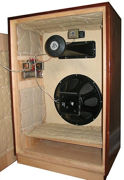
---------------- On 1/22/2005 10:31:19 PM BEC wrote: Here is a picture of the insides of a Cornwall II Vertical. Bob ---------------- Thanks Bob C., Looking at that interior, the padding looks like it could possibly be thin fiberglass with a fabric or paper cover. What is that stuff? Is this a converted Cornwall? I was looking at an old advertisement and the Cornwalls were at one time offered in a vertical horn version. I was left with the impression that these cabinets were intended to be placed horizontal. They offered an optional base for this cabinet as well.
-
---------------- On 1/22/2005 8:59:23 PM jwcullison wrote: This is very helpful. That lining wouldn't take up too much volume. Again, to me the wood doesn't look to be beveled when put together. I have noticed the Heritage line doesn't do this. This would probably change your schematic/drawing. Also, on your front view, the markings to show the width of the top piece of wood don't go all the way to the right side. I am assuming your measurement howeveer is correct. jc ---------------- JC, You are correct. I placed the right drawing extension line in the wrong spot. I rushed a little doing the drawing but what do you want for 30 minutes of work. The final version will be checked much closer. I have updated the drawing with the base dimensions supplied by I.B.Slammin and corrected the misplaced dim line. The mitered corners vs. butt jointed corners has been explained...in the post above. Thank you by the way. The explaination makes perfect sense. I think Klipsch used lumbercore material on their better finishes. That stuff would be just plain ugly with an exposed edge. As far as the lining goes, I think there are better materials to reduce internal cabinet reflections. The black interior cabinet in the photo above was later covered internally with foam eggcrate material. In fact the use of spun fiberglass actually allows the cabinet to work as if it were larger (more internal volume). I'm still looking for the cutout sizes for the LF driver and horns with placement measurements. Any additional measurements and data I get will be added to the drawing. If you see anything that is incorrect, measurements or whatever please make mention of it. Jim
-
Try a small suction cup. It might work. There is a good possibility it will still have some creases even if you manage to pull out the dimple.
-
Here is another picture of a different model. Note this one has butt joints instead of mitered corners. Also note the dampning material. It looks like tear-off paper packing.