Jim E
-
Posts
129 -
Joined
-
Last visited
Content Type
Forums
Events
Gallery
Everything posted by Jim E
-
This is the two port layout. Cornwall2Port.pdf
-
I'm a bit of a stickler for details also. If there are any errors on the layout, I would be happy to correct them in the drawings. To the best of my knowledge the measurements supplied to me by the forum members were correct. I doubt a small change in the port opening will result in a noticable decrease in performance. Jim Cornwall.pdf
-
Correct as usual Duke...consumer audio is typically around -20 dBu at 50% modulation isn't it? I would think the EQ should be the last item in the chain before the amps. Set the input and output gain with a 1 kHz @ -20 dBu tone and be done with it.
-
What is the padding material inside the cornwall?
Jim E replied to damonrpayne's topic in Technical/Restorations
The material I believe is multilayered tissue paper seamed or stitched together. I'm pretty sure it is still used as a packing material for shipping. It should soften internal cabinet reflections a little bit. As I understand from others on this board, using fiberglass would change the sound in a negative way. -
Scott, I know what you mean. Labor unions in many areas have been forced out over the last 40 years. At my location we are all union with the exception of security and upper management. I work with our electrical department (Local 40 IBEW) often. I can honestly say they are great guys with plenty of experiance. They are of course very conscious of following electrical code. In the context of this thread on "center referencing of the ground on a 120v circuit" the answer would be no. We do however use isolated three phase transformers for the audio and electronic equipment in each screening room. The audio is all on the same phase and most all of the equipment is balanced line. We have isolated ground bars in each equipment rack along with isolated receptacles and grounds. A star ground is used for outboard projectors and equipment to the racks. The isolated grounds are routed in heavy insulated cable back to the power room separately from the AC panel and is connected to the transformer ground buss and the building steel. There are separate panels for all the other stuff with more conventional wiring. If you ever get out to the West Coast let me know. Be glad to show you the layout. Nothing fancy, just solid. I might even be persuaded into a demo.
-
Scott, I am in the motion picture industry here in Hollywood. Specifically I engineer and install film and digital projection systems and their related sound systems. In short, I've got the best job possible because I work with what I enjoy. I've been an IATSE union member for 35 years and I'm still learning. What I meant by dedicated neutrals and grounds is that many times I have found some people including electricians will install one (sometimes oversized) neutral for two or three circuits and a single ground. By electrical code this is basically correct if you are dealing with 3 phase. When dealing with multiple same phase circuits, sharing a neutral is obviously not a good practice. Properly wired the neutral has the same load as the hot. As far as grounds are concerned, you are correct that they should be already bonded somewhere in the panel. Again many electricians believe the condiut will suffice for a ground. While the conduit will provide some shock safety, it often corrodes at couplings and doesn't do much until a full short occurs welding the joint. A solid ground is needed for electronics. I prefer and specify separate and sometimes isolated grounds in any installation. Poor grounds are often hard to locate and often overlooked. A separate grounding rod into the earth can be prudent as electricity will most always take the path of least resistance. Depending on your location it should be deep enough to hit moist earth to be effective. Hey! You guys think I'm being too "Old School"?
-
"If you have good clean power" by my definition was spelled out. Speakerfritz, I am not trying to cast doubt on your post. I am sure you are sincere. Quite the opposite, I've seen people go to many extremes in the quest of better audio. The cost for these extremes can be staggering and often lead to marginal improvement if any. I am only suggesting an alternative that could work for perhaps 95% of the people with similar problems. I live in Southern California and if you watch the news, each summer we have electrical power shortages and sometimes they shut-off entire areas to prevent total failure. I don't live in NYC and your location may need additional gadgetry to reach your goal. I must say that adding a single phase 220/230 stepdown or isolation transformer will not rid you of local power fluctuation. Fortunately most modern audio equipment is designed to operate within the estimated voltage range in the real world. It is interesting to note in the early days of commercial audio much of the equipment was DC and battery powered systems were very common. Maybe they had it right the first time. I'll try again to explain and elaborate. Home runs to the mains panel, the lines should not be shared by items that can generate spikes or have high in-rush current on startup. For example thyristor type dimmer and speed modules (aka diac/triac or scr light dimmers/motor speed controlers) can introduce noise into the line not only through the "Hot" but any shared neutrals as well. This can happen even when they are designed as a zero-crossing device. High in-rush and current hogs will cause dropout or low current conditions for other equipment on the same line. Have dedicated neutrals and grounds for each circuit. Adding an "earth" or technical ground can help. It could save you and your stuff in an electrical storm as well. Balance the electrical load in your panel. If you are not an electrician don't even think about doing the work yourself. This will never be precise as many items that draw current are not used all the time. It is beneficial to operate all of your audio and video equipment on the same leg or phase of the power panel. This applies to single connected systems. If you have multiple systems within your home they can be on the other phase for balancing purposes. I have one question for you. What is it that you are hearing that is causing you all this grief? If your surroundings in NY are as you stated, you must have spent a fortune to get you listening area so quiet. The noise floor on CD is very low (unless you count poor recordings as part of the noise). FYI, some power companies will install (on a temporary basis) a digital powerline monitor to assist in finding supply issues. These can track and record typical problems for say a week. As you said, they have replaced the transformer several times. There may be other issues that have not been addressed.
-
Scott, I am in agreement with you. A clean run or multiple runs of power from the mains panel with a good ground has always worked for me. In a typical home the wall outlets are shared and all too often things like air conditioners, ceiling fans, dimmers, refrigerators etc. are on the same feeds. While this construction practice is legal and keeps the cost of building down, it does not always work for audio or other sensitive equipment. In my present system I have two 12 gauge (12/2 copper romex with ground) home runs to the mains with dedicated grounds and a supplemental copper rod earth ground spiked 15 feet into terra firma. It took me a full day to install and the cost was under a hundred bucks. It seems to work just fine for me as long as SoCal Edison is doing their job. Most audio equipment generally have sufficient power supplies that do a good job regulating the AC into the proper DC voltages and filtering out 50/60 cycle hum. Many supplies also have MOV surge suppressors in their design to filter over voltage spikes and circuitry to minimize other line transients. Most audio equipment utillize a single primary stepdown transformer that is as far as I can relate not critical of line polarity (hot or neutral) so how the power is "balanced" would seem to be of no importance. What is important is if you have sufficient current and voltage available and is it clean. If not then dedicated power isolation devices and/or home runs may be the answer. If you are using large high output amplifiers on the same circuit as your other low wattage components be sure they are not pulling the line low. Some power amps can pull well over 20 amps at full tilt. If you have good clean power and still have noise, then check your equipment and interconnects. Also keep in mind that the requirements in a recording studio or other professional environment are somewhat different than the home audio setup.
-
Forgot one thing. You would move the baffle or "motorboard" forward to match flush with the sides. I don't believe it would be needed however the overall depth of the cabinet could be reduced by 5/8" as well to retain the same internal space.
-
You are right Colter, I stand corrected. The decorator models were butt joints however, I stand on the dimensions of the cabinet. Whenever you build anything in wood the builder must compensate for the thickness of material, joint type etc. With speaker cabinets the inside measurements are usually what counts as the internal volume is designed to match the driver(s). As the Cornwalls main panels were constructed of 3/4" material you would add 1 1/2" to the front baffle height and remove remove 1 1/2" from the width and 3/4" from the depth of the top and bottom panel. Here is a really good post by HDBRbuilder that removes the mystery and cuts to the chase on decorator models: OK...let me try to explain some of this "decorator" speaker stuff as best I can. "D" style, or "decorator" style cabinets were a lower-cost alternative for the consumer of SOME of the Klipsch designs of the original "Heritage" series speakers, with the EXCEPTION of "D" style LaScalas and Belle Klipsch speakers. OFFICIALLY, there were never any "decorator" Belle Klipsch speakers made(although there WERE at least two pairs of BIRCH Belle Klipsch speakers made while I worked there (76-83)! The LaScala, or course, was always made out of plywood, so, in effect, ALL OF THOSE were "decorator" models. The intent of "Decorator" models was that the consumer could use these in a wide variety of applications while saving some money on the purchase costs as compared to the cost of fine-veneered models. The "decorator" style k-horns are likely the major exception to this rule, since MOST of these were used in nightclub or other professional applications...or immediatley modified by owners into C-style cabinets. The original decorator cabinets for Heresy and Cornwall speakers were what we at the plant called the "flush-front" models. On these models, the assembly of the cabinets was using glue and nails ONLY...with no glue blocks used in actual construction of the boxes, except for the rear of the cabinets, where they were used for mounting the speaker back panel to the cabinet with screws. This cabinet design was extremely strong, and could take falls from over 6 feet onto a corner of the cabinet, usually with no major STRUCTURAL damage. The idea behind decorator models was that the owner could save money on his/her purchase and still have a number of viable options in which to employ the speakers. They could be built into the walls between studs (especially good possibility in rooms with closets on walls opposite wall speakers were mounted into); they could just be painted to match the room decor, and grille cloth matching the room decor could be stapled to the front with trim tacked over the edges of the grille cloth; or they could be stained and finished to match other furniture in the room. You would be surprised how many were finished out quite nicely by home craftsmen...using inexpensive moldings and such to cover the exposed plys on the cabinet. Now, here is the big clincher...By the time I began working at Klipsch, the company had been in a "new" building for just a very few years (2 or 3), but an addition to that building, which more than doubled the size of the plant, was just being completed when I got hired on (July 1976). Within two months, the plant had overflowed into this new addition and within another year and a half it was determined that even this new addition was not large enough for the expansion the company needed at the time! How did Klipsch manage to grow so fast at a time when other speaker manufacturers were going under? Simple answer is: Decorator Heresys!! Just figure it this way: In a normal 40-hr week of production, maybe 10-12 K-horns, 10-70 Cornwalls of all kinds(depending on orders), 5-7 Belle Klipsch speakers, 15-35 LaScalas, 150-250 NON-decorator Heresys, and at least 350-700 DECORATOR HERESYS, were produced! The Klipschorn is what made Klipsch famous, but the HERESY, and, in particular, the DECORATOR HERESY, is what made the company PROFITABLE, and KEPT the company SOLVENT through times when other speaker/audio companies were going under right and left! OK, so just when and WHY did the company change the cabinet design for the "decorator" Cornwalls and Heresys? Well...as the decorator Heresys began to sell more and more, it was noticed that more and more often, the orders came for them to have grille cloth on them. Well, the flush-front models required the cloth be stretched across the front panel, then stapled around the edges of the front, then molding (screen-door moldings) be mitered to length and bradded-on to cover these stapled-on edges of the cloth. This was a time-consuming and labor-intensive procedure, and, ESPECIALLY since it was being applied to the low-cost version of the cabinets, the decision was made to change the cabinet construction so that the same grille-cloth panels installed on the mitered-corner finely-veneered Heresys could be used on the decorator style Heresys! Since the new cabinet-build had the front being "dropped-in" and stapled onto recessed glue blocks, just as on the mitered Heresys, we at the plant called them drop-in-front-style decorator Heresys. This change for decorator Heresys was initiated in the fall of 1977. Since there was never a huge amount of Cornwalls built at that time, and since it was no big hurry in making the changes necessary to do the Cornwall build, it was not until around the beginning of the second calendar quarter of 1978 that the decorator Cornwalls got the same drop-in-front kind of cabinet design....for the same reason as the decorator Heresys got the change. Another thing happened about the same time as these cabinet changes. The change of the NAMES of these speakers happened, too! Here is the "skinny" on that change. The expansion of the plant in 1976 had brought about a small hiring spree of folks at the plant in order to keep production up. Many of these new hires were good workers, but there are always a few who just didn't "cut the mustard"...and were sent on their way to other pastures. As things went at that time at the plant, most new hires were sent to the cabinet shop to begin with, if for no other reason than to learn how the speakers were built and to help out in production of parts for them. If they turned out to be good at building, they were kept, but if NOT, then they were sent to sanding...to see how they worked out there. If they didn't work out in sanding, then they were sent to finishing, where they started out applying oil finish to oiled speakers...and hand-sanding sealer coats on speakers getting laquer finishes. If they didn't work out there, they normally went to final assembly or straight to shippping. Shipping was normally their last stop before having to find another job elsewhere. The major point here is that, although there were SOME old hands in final assembly and shipping, MANY of the new people in those areas had already "flunked-out" in other areas of the plant..and it was just a matter of time before they were out the door job-hunting again. OK, remember that the change-over in the build of the decorator Heresy cabinet occurred in the fall of 1977. THAT same fall was a record sales period for the company, with November of 1977 being the first million-dollar sales month in the history of the company! The company had a number of new employees hired-on just to keep up with production in final assembly and shipping that fall. In final assembly, most of these new hires were basically doing mundane tasks that were time-consuming for the regular final assembly workers...such as filling-out the info on the labels for the backs of speakers, moving pallets of parts up to the worktables, dropping backs into cabinets for the regular folks to secure with screws, etc. It was not noticed so much during the flurry of activity at the plant that fall, but it WAS noticed at many of the dealers, that not only were SOME of the labels on the backs of speakers NOT filled-out properly, BUT many were either not filled-out at all, or were unreadable. It was also noticed that many of the labels for Decorator Heresys and Cornwalls had the "D" left out of the model designation. Up to that point in time, an unfinished Decorator Heresy was called "HDBR"...and unfinished Decorator Cornwall was called "CDBR" ...but many of the labels just had HBR or CBR on them...WHY? Simply put...confusion of the new employees over model type variations. For example, HWL was Heresy Walnut Laquer, so why wasn't a laquered birch Heresy called HBL?...instead of HDBL? Many of these new employees just never could get it straight. The "powers that be" made a decision at that point...to DROP the "D" from the decorator Cornwalls and Heresys in the designation on the labels...for a number of reasons. First, it saved time, by having one less thing to write on the labels. Second, since all birch Heresy speakers were now being sent out with grille cloth panels included, they were not as much of a "decorator" style as they had previously been. Third, since all the decorator Heresys now came with grille cloth panels, it was necessary to raise their price to adjust for the addition of that panel. It was easier to just call them something besides decorator models...something that more closely aligned the new cabinet style with the cabinet style of the mitered ones with the same grille cloth panels...and those mitered ones had a three-letter designation (generally speaking)...so the new three-letter designation was picked up for the decorator models....leaving out the "D" from that designation. ALthough the "D" was left out of the new "OFFICIAL" designation for the birch Heresy cabinets, the plant folks still called them decorator models in-house. When the change to the Cornwall cabinets occurred in the spring of 1978, the same designation change to them occurred, the "D" was dropped. OK...now let me cover the differences between vertical-horn Cornwalls and horizontal horn Cornwalls. From a cabinet-build viewpoint, the only difference is the orientation of the horns and woofer on the motorboard (front panel). Other than that, they are indentical in EACH build! IOW...the only CABINET difference is the router form used to rout-out the motorboard for them! Some people claim they have "two-port" or "three-port" Cornwalls of either vertical or horizontal driver/horn lens orientation. Actually, the Cornwall only has ONE PORT extending along the end of the motorboard, opposite from the high-frequency "end" of the motorboard. The openings in that motorboard, FOR THAT ONE PORT, are either two or three openings. WHY? Just look on the port as ONE WIDE OPENING, but WITH a reinforcing "STRUT" in its center, to provide some extra frontal structural strength to that END PANEL of the cabinet. In the case of three openings, you have two reinforcing "struts". That is ALL THERE IS TO IT! NOTHING MORE, NOTHING LESS! BTW...if you measure the TOTAL area in square inches of the openings in the so-called two-port and so-called three-port Cornwalls, you will find out that the TOTAL opening area is almost EXACTLY the SAME! One note here that may be of interest to some of you. The router forms' BASES for these speakers were originally made out of steel plates, which made them rather heavy and unwieldy to use on the overhead router. Those steel plates also tend to wear heavily on the pins on the router table of the overhead router. Since the easiest way to empty a router form of built-up sawdust is to flip it over, its weight tended to ALSO wear out the poor soul who was stuck routing these parts all day long (meaning ME...for most of the time I worked there!). Also, as time went on and modifications to parts became necessary, it was very expensive to have a machine shop lay-out and mill the openings into new STEEL router form bottom plates. So, sometime around 1978-79, we went to using tempered masonite for the base plates of the overhead router forms, since those could be easily made "in-house" and since tempered masonite had no tendency to wear down the pins on the router table. We still continued to use the steel-base-plated router forms until they either became obsolete or wore out, though. The first forms to become made of tempered masonite were the ones for Heresy fronts, of course, since they were the most used in the plant! When the new masonite bases were made for Cornwall fronts, they had three port openings in them, partly because it made the ROUTER FORM hold up better to use by new employees who tended to let the router pin SLAM into corners while routing the parts...which would have rendered the form useless in a short time if there had only been two port-openings in the base of it! Even with three openings, those bases on the Cornwall front forms had to be replaced regularly thanks to the slamming of the pins into the corners of the openings by router newbies! One other note...although there is a distinct time at which the vertical Cornwall II became a non-standard build (IOW, it was no longer OFFICIALLY offered as a model), it was still built...even up until I left the company in 1983! It seemed that I had to rout out a few fronts for vertical-horned Cornwalls every year I worked there...due to special orders for them...NORMALLY a special order for a SINGLE one...to match one an owner already had purchased for his previous monaural system, but who was changing over to stereo and needed a second one to match his first one. I don't know whether the vertical ones were offered on special order after I left in 1983 or not, but I doubt they were offered past the advent of the 1985 Cornwall II version! Thanks HDBRbuilder, I enjoy your posts and inside info. It must have been quite a time at Klipsch. Not many manufacturors like Klipsch around these days. Most are CNC cut and fold with vinyl finish. Jim
-
DrFish, I believe the only difference on the cabinet measurements is the "decorator" models had mitered corners. In any case, if you have the drivers it is should be an easy build for someone with fair woodworking skills. After many posts on the DIY of these cabinets I think we concluded the small differences other board members found on various model years would result in no significant change to the sound. I have included a PDF file for the Cornwall in this post if it helps. I have heard the new Cornwall III models have the LF driver repositioned on the baffle and I'm sure there are some other changes as well. Perhaps these changes could be incorporated into the build. Cornwall.pdf
-
The product you mention might work fine if applied in several thin coats however the possibility of blocking the weave is very real. Most grille fabric is made of synthetic fiber and won't dye very well as the material is generally non-porous. Traditional cloth dyes are water based. Another method that may work is leather or shoe dye with a sponge applicator. Try a small patch area first. If you look on this forum there are several posts on replacement grille cloth material. It is actually not terribly difficult to install new material and the possibility of clogging the weave would be eliminated. As a bonus you have a choice of dozens of different weave patterns and colors.
-
OK. Will this work?

-
I have installed JBL 3632's which use two 6" cone midhorns (larger versions have four drivers). We crossed these over at 313 Hz and just under 2 kHz on the top end. The setup tuned in quite well with the crossover points blending smoothly. The end result was a very natural smooth mid range with no loss in dynamics or gain in distortion. IMHO JBL did their home work. This approach has much merit. As power handling and/or distortion is at times an issue (diaphragm excursion) for some compression drivers below say 400 Hz, the cone driven mid-horn makes sense. Not to mention the physical size of a proper horn. In the case of folded bass horns such as the Klipschorn isn't the upper end falling off around 300 or 350 Hz?
-
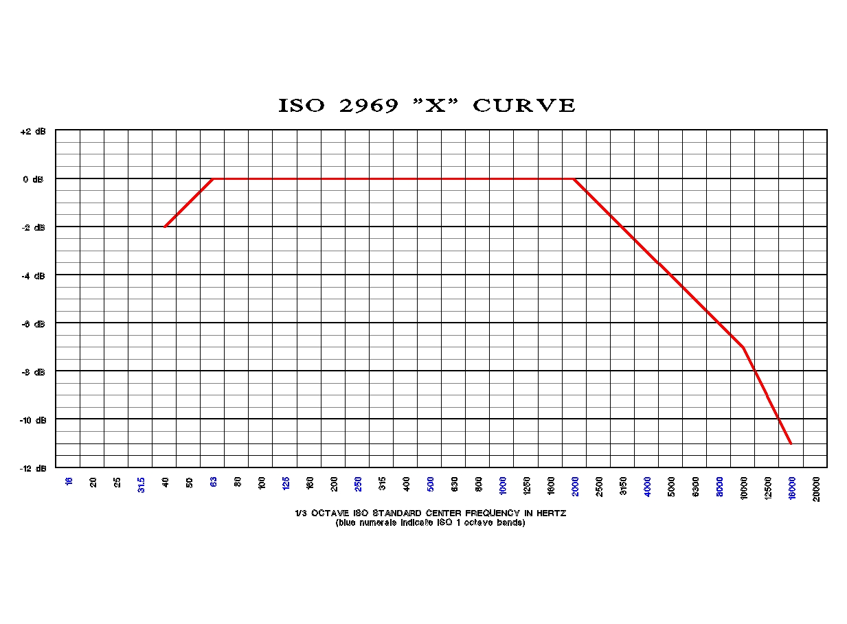
Here is the curve
-
I'm in agreement with Duke. I wouldn't cut the fins. They don't make these anymore and there are many other ways to dampen the so called "ringing" without destroying the horn. Try some modeling clay and/or Dynomat before you make any cuts.
-
The spec you are refering to is the standard SMPTE ISO 2969 curve used for motion picture theatre alignment. The basic specification calls for a rolloff of 3dB per octave past 2 kHz. The intent for the filter was to help avoid excessive amounts of equalization being used in the surround channels. Typical cinema processors of that era from Dolby, Ultra-Stereo and most other manufacturers used op-amp one third octave eq with about 6 dB of range. Often there is not enough range to reach good settings in the auditorium and dialing in too much eq can introduce phase problems. JBL also includes a circuit like this in several of their surround speakers as well. Some of the JBL's include a switch to disable the filter if not needed.
-
I'm reasonably sure the convention of the "center alignment of drivers" is to improve the localization of the speaker. While two or three way systems are not technically point source speakers, stereo imageing is still important and offsetting drivers side to side would cause a bit of smearing. You could correct this with time delays but you would be locked in on your listening position and the cost of a three way electronic crossover, additional amplification and wiring is no small concern. As a note though, bi-amping and/or tri-amping with time delays will give you a huge bang for the buck. I have been bi-amping my systems for almost thirty years and it's worth every cent. It is amazing how well our hearing can detect small changes in the direction and timing of sound. I guess it came in rather handy when we were hunters and prey.[] Certainly try several mounting positions and listen to the setup before you commit. I would suggest using string instrument source material. I my opinion, the tweet does look sweet mounted to the side.
-
I am willing to lay the assembly out but I will need measurements on your proposed drivers and adapters. I will also need the correct measurements of your Klipschorn top cover. I personally would prefer to use Altec 802-16G or 902-16A or B drivers on that 511 horn. Jim
-
I agree. It is wrong. So what happened to the "Home Version" of the Jubilee? Does anyone know for certain if these will ever be produced and made available to consumers by Klipsch? In my opinion, the commercial version with the supplied HF horn would be large and overpowering in most home situations (unless you believe too much is always enough). Those puppys' are built to project into 200 + seat theatre auditoriums through a perforated screen. Keep in mind theatres are tuned to the SMPTE ISO 2969 curve (if installed correctly) which basically means they roll off 3dB per octave past 2 kHz and 4dB per octave past 5 kHz. I like the look of the commercial version but, the horn assembly would just be wrong in a living room setting. I could see using the bass bin perhaps if you had plenty of room. IMHO one should think twice about buying these for home use. For the few who would want them I see no harm in DIY. There would be no profit in re-producing a speaker of this type. People who want Klipsch Pro gear will buy Klipsch not a copy or a look-alike. For most people that build up their own audio systems and there are more than a few here, audio is a never ending experiment. A quest for audio nirvana. Like many others I enjoy this kind of torture. Until and if Klipsch produces the consumer type perhaps the answer is just buy the bass bin and roll your own top-end.
-
BigD, I followed your build of the Jubilee. Your design version without the passive radiator certainly makes the most of the given criteria that was posed. A very nice build. I really would like to know how they sound. Is the bass extension comparible to the KHorn? With fewer folds I would expect the bass to be somewhat cleaner and better defined. Jim
-
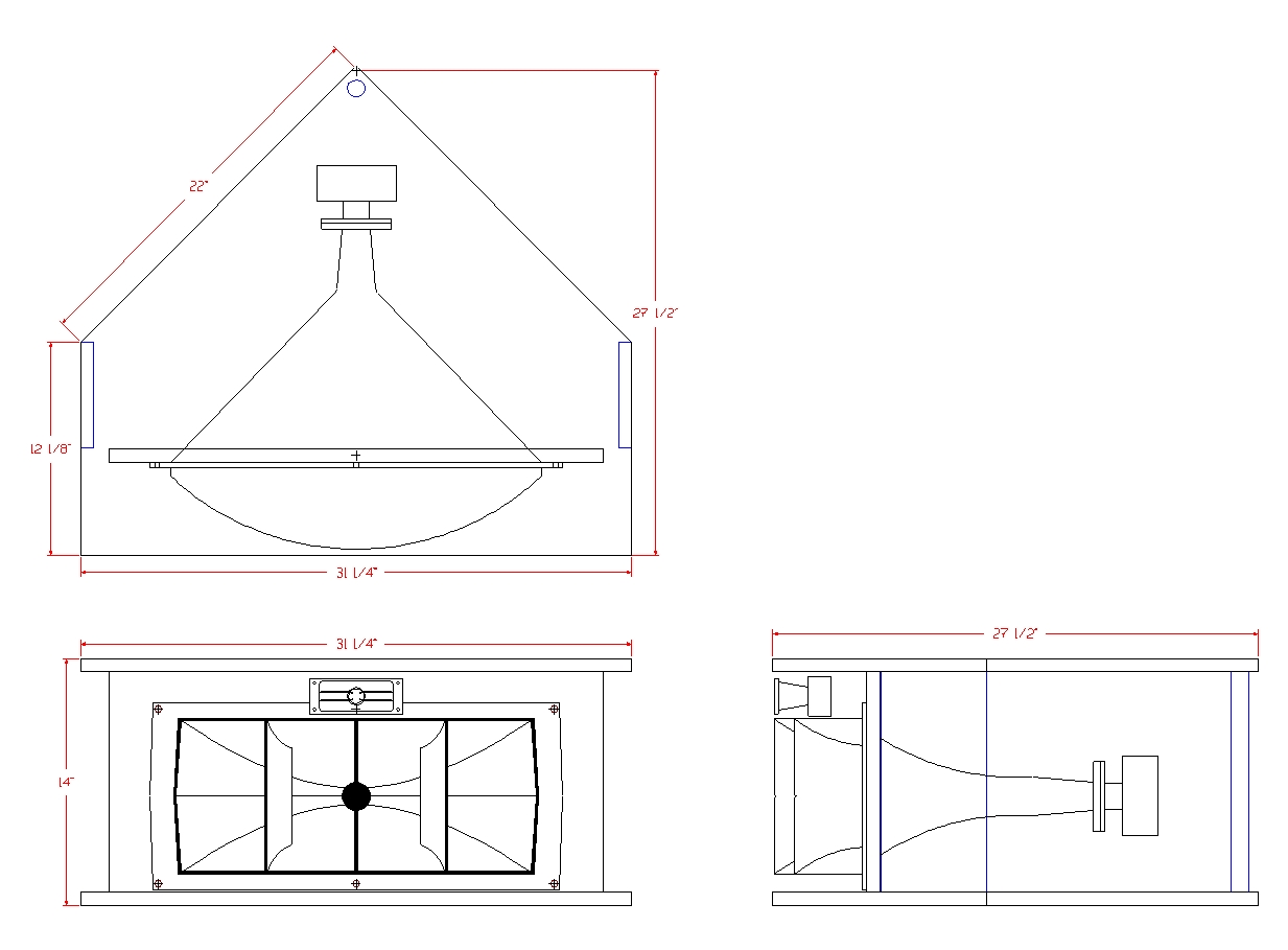
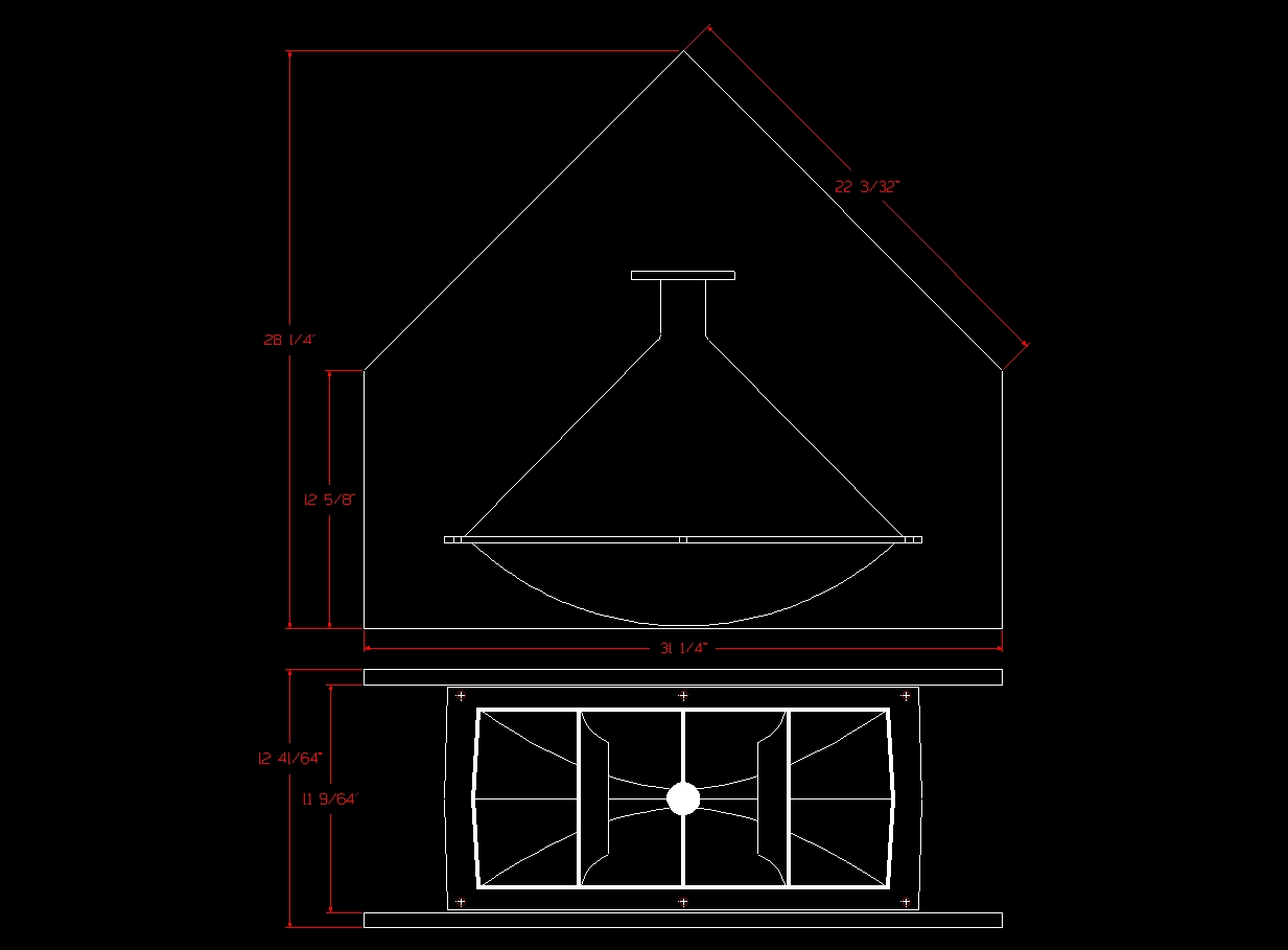
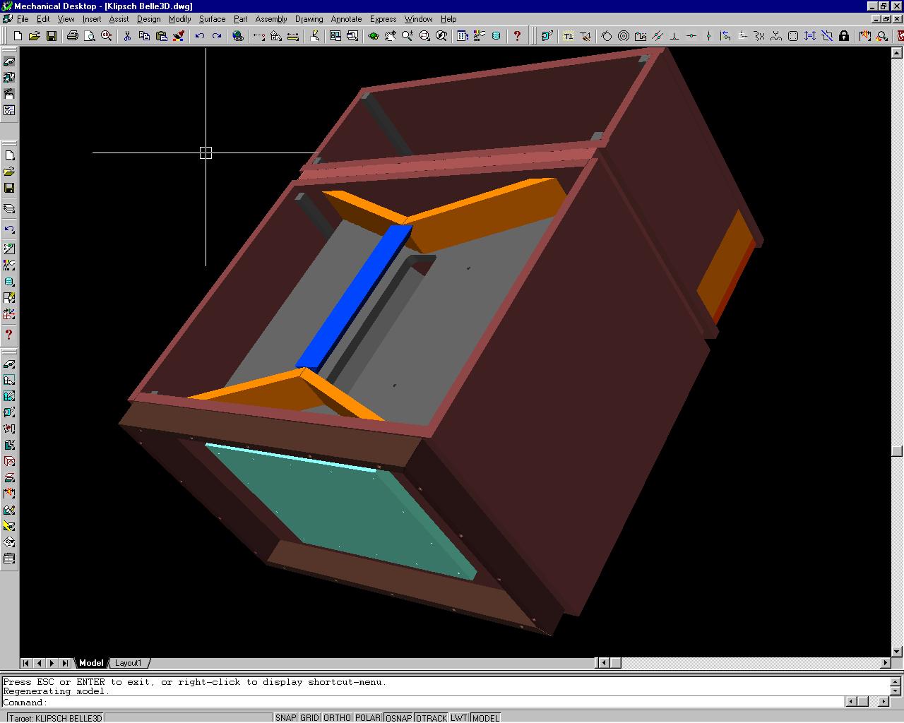
Thank you Jordan. I've had this sitting in the files for quite some time. There is some confusion on the driver(s) and "motor board" configuration that prevented a completed drawing. I know others have drawn out the Jubilee but, I still wonder about the passive radiator and motor board (baffle) layout. Here is a rear view of the Belle with the back removed exposing the baffle detail:
-
I'm with you Duke, this needs to be finalized for the DIYer's. Willin' to help if needed.
-
Building interconnects - need advice on digital cable
Jim E replied to tigerwoodKhorns's topic in Technical/Restorations
When using wire interconnects for digital for either AES/EBU or SPDIFF, you should use well shielded110 ohm wire designed for digital. Belden, Canare and Mogami all make a good product. Your connectors will work fine. You mentioned XLR's...If your input or output is ballanced line and the other end is not, you will need either an inline transformer or active conversion to unballanced. The coax is a no brainer as the adapter was supplied but the RCA connects should still be the mentioned110 ohm wire. Hope this helps. Jim -
The upper half of the cabinet will come off but it is a little difficult.