


PrestonTom
-
Posts
4394 -
Joined
-
Last visited
Content Type
Forums
Events
Gallery
Posts posted by PrestonTom
-
-
Step Three continued.
This is simply the the edge view from step three. The 1x3 poplar (or pine) will hide the 2x4s and edges of the MDF

-
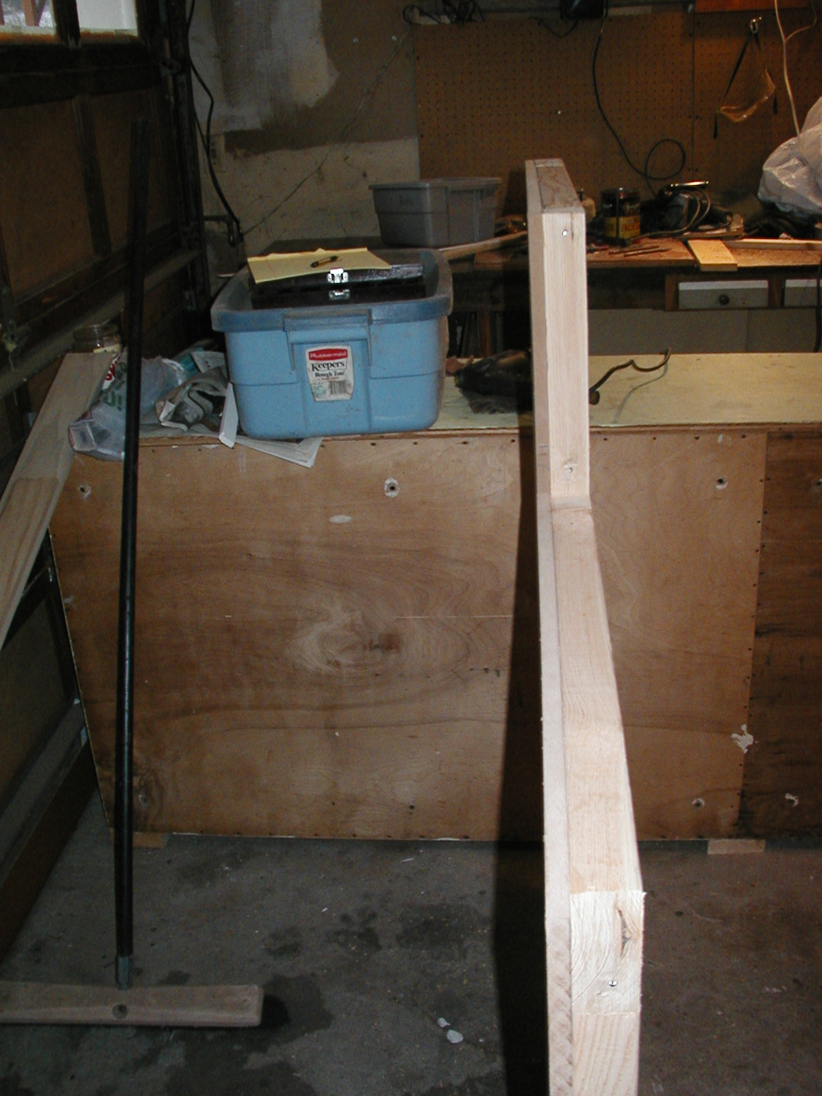
Step Three: This depicts the bracing with the MDF nailed on one side. Use plenty to nails and glue to stiffen up this structure. I chose to orient the 2x4s on the thin side so the total thickness is only 2.5" thick (the MDF was 1/2"). This was a design decision and certainly one could use 3/4" MDF and also re-orient the 2x4s in the other direction (if you do so you will need longer toggle bolts).
Incidentally all materials are available at Home Depot and if you do not have a truck you can get the MDF in 2x4 or 4x4 sheets ( I used 4 2x4 sheets). By mounting the MDF up on the 2x4s (see bottom of picture) I was able to lift the entire corner to about 51.5" (since the MDF is only 48") before the final trim goes on. Incidentally the bottom pair of 2x4s were oriented in the wide direction so the MDF would fit on top of them. In order to get the proper width, the 2x4 were ripped down their length. This is trivial with a table saw but a bit tricky if you are using a circular saw. However the final trim moulding will cover the 2x4s and most mistakes.
This total height will clear the top of the speaker cabinet. The front half was not as tall. This was a design issue since I did not want the back of the corner (which faces my front hall to be too obtrusive - again it is a series of compromises) But the front should be at least as tall as the bass bin. Notice the center/vertical 2x4 runs the entire height (and is notched). If you are using small sheets of MDF (as done here with 2' x 4' sheets) and making the front half not as tall, then make sure this center "post" is constructed this way.
At this point you should align the false corner with the cabinet and mark the holes (on the false corner) where the toggle bolts will go through (if you look carefully you can see them in the photos on the right side in the 2nd 2x4 down from the top). Note that my false corner has a strip of pipe foam that is glued (contact cement) on the very bottom of the structure. Put this on now before making the measure. The pipe foam was 1.5" diam and then cut down the middle. This gives an airtight seal on the bottom and allows you to slide the false corner into position.It also adds to the height of the false corner - so take this into account. It also protects my hardwood floors from scratches. It is best to use contact cement rather then mechanical fasteners because they might scratch the floor or snag a carpet.
The verticals on the left side (you are looking at the outside of the corner - not the speaker side) will later have 1x3" poplar (or pine) ripped to the proper width and nailed (finish nails) to the edges as well as the horizontals (tops). this will add an extra 3/4" and provide a smooth surface for painting (as opposed to the rough 2x4 material. Include this thickness in your measurements.
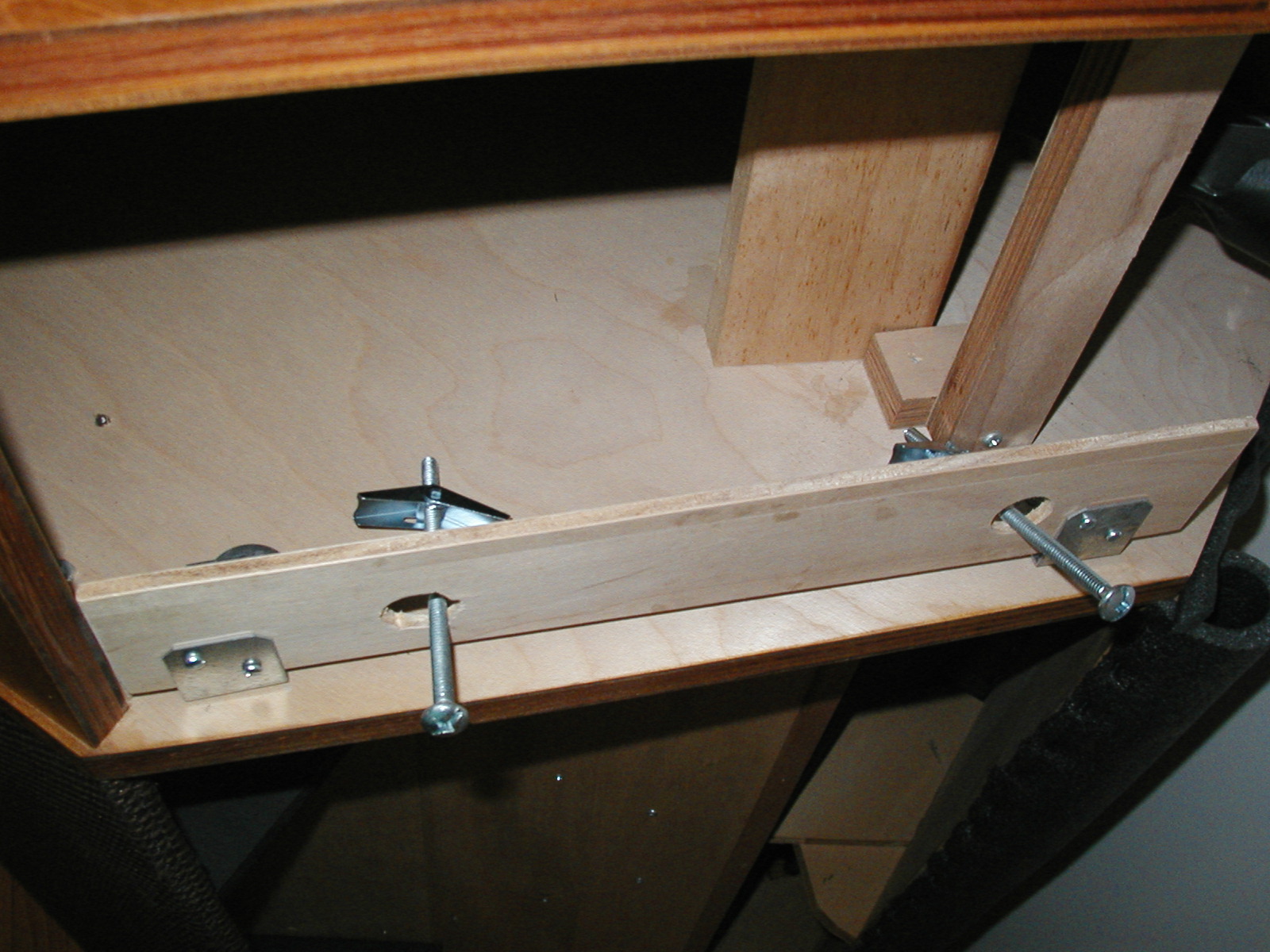
-
Step Two: Use a piece of thin plywood for later attachment to the brackets. Then drill a pair of holes to receive the toggle bolts. I used bolts that were 5" long. By mounting this plate you can be less precise in drilling the corresponding holes in the false corner (that the toggle bolts will go through). Also, by using toggle bolts you are not drilling into the actual cabinet. This a can also be unfastened and re-fastened a number of times without chewing up the wood. Remember that doing this on the right side of the cabinet is easier. If mounting on the left side, you will need to avoid the crossover. You will notice some flex in the plywood plate. This is okay. You are not trying to directly couple the false corner to the cabinet. In fact the pipe foam (attached later to the horizontal) will create the seal and also help dampen the vibration to the false corner (via the impedance mismatches between the cabinet/pipe foam/false corner). You do not want sympathetic vibration in the false corner. This possible vibration is also minimized since the false corner is sufficiently massive and dense (thanks to the MDF construction with loads of nails and glue and bracing) - the beast will eventually weigh 96 lbs. I know since I had to carry it up the stairs.
-
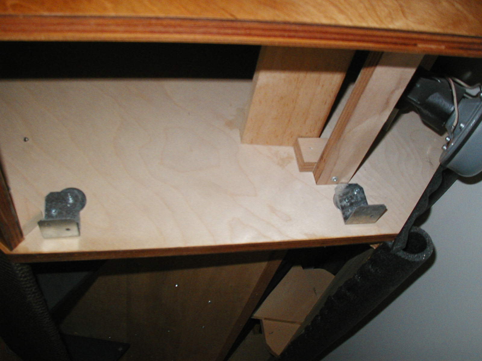
Step One: mount 2 brackets with small screws (less than 3/4"). These do not have to be massive and will be used to pull the false corner to the cabinet (actually the pipe foam insulation on the horizontal - which is removed in this photo). The pipe insulation acts to seal or close the volume (the final flare of the horn). Since the foam is somewaht air-tight (just try and blow through it to see this) it only needs to be a snug fit. You will not need a lot of brute force to make this sufficiently tight.
-
I am showing off the result of my latest project. The attached file shows a fairly simple false corner.
Although it is half a corner, maybe we should call it a "false wall". This was inspired and designed by modifying some very helpful info that I found in various threads. My goals were create a false corner that was 1) portable, 2) somewhat unobtrusive and having some design elements that would compliment the listening room 3) not alienate my girl friend and 4) not cause irreversible modifications to my K-Horns. I'll post the construction details and hopefully inspire some others. It is a fairly simple build. It only requires a single 4x8 sheet of MDF a, some 2x4's and moulding (which can also be chosen to compliment your specific application).
Importantly, it allows one to put their K-Horns in a corner (this is critical and if you're not doing this already, you are in store for a big improvement) and perhaps also to space them apart for improved imaging. Again, this capitalizes on the work of others, but includes some details that may solve some individual problems.
Good luck and I hope this is helpful.
-Tom
-
I have recently positioned my K-Horns along the long wall (about 18' and forming a 90 deg angle) and I am experiencing the "hole in the middle". Although I am toying with the idea of building a clone of a Belle or La Scala to use as a center, I am wondering about anyone's 1st hand experience when using a Heresy as a center channel (this is strictly for music, not HT).
Specifically, is the voicing between the Heresy and the K-Horn similar enough in the mids and highs (I realize this is an open-ended question). Also, do I need to worry about altering the crossover to minimize the blending the low frequencies (which are quite mismatched & I would not want to interfer with the superb bass response of the K-Horns)?
The Heresys are frequently avaliable and popular. So if the experiment is not a success, I could always turn them over.
Your thoughts and experience are welcome.
-Tom
-
Good Afternoon: I have been lurking for the last 6 months and it is about time to say hello. I have been particularly impresessed with the enthusiasm and level of knowlwedge shown by the members. About 10 years ago I picked up a pair of used K-Horns and I have been hooked ever since (probably not an unfamiliar tale).
Last month I made a modified/partial false corner (capitalizing on some of the good information found in the various threads). This has allowed me to put the Horns along the long wall in my listening room (about 18' apart and listening at a depth of about 10', of course providing the suggested 90 deg angle). This has really opened up the listening experience and provides for a better on-axis frequency response. Eventually I will post some pictures of the false corner I constructed since it has some features that others might be able to use (ease of construction, WAF & portability).
Now to my question. With the new configuration, I have a much better appreciation of the "hole in the middle" problem. Although in some ways it is also magnifies any fragility in the "sweet spot" . Alas! I am in the process of talking myself into getting a center channel to fill things in. I have fooled around with an extra Vandersteen speaker, amp & pre-amp (with a mono switch) I have available. In terms of the listening geometry the results are a success. In terms of the voicing the results are poor (as one might expect when mixing such different beasts). I obviously need a center that is driven by horns. Using a Belle or even a LaScala would seem a reasonable choice (although an expensive one). However, I enjoy wood working so I am intending to build a Belle-clone and either trying to get "authentic parts" from e-bay or perhaps substituting some interesting components for the mid and tweeter(perhaps altec). This of course brings up a number of issues on crossover-decisions, and would the frequency & phase responses between the modified center and the K-Horns be close enough to adquately match the voicing between the two, etc. etc.
I have been long winded. But I think you understand the issues I am struggling with. It is also a nice way to say hello to everyone. I appreciate your thoughts and would value your collective experience.
Thanks - Tom

Simple False Corner
in Technical/Restorations
Posted
Step Four:
I chose to fill the voids with insulation. This picture shows far too much insulation being stuffed in there - I eventually removed some (and yes, it is very itchy). An alternative is to fill the cavities with sand. This may be a bit over the top however.
Note, since the toggle bolts go thorough a 2x4 brace the sand would not spill out.
Next step is to go ahead and attach the MDF on the other side with glue and nails
Then : Finish drilling the toggle bolts holes through the other side (MDF)
Then: drill a recess through the MDF for the head of the toggle bolt (a cap can fit into the recess and will be flush with the surface). Just make sure this cap or cover is removable.