kennyno
-
Posts
15 -
Joined
-
Last visited
kennyno's Achievements
Member (2/9)
0
Reputation
-
I am going to try a mod on a old Chase technologies RLC-1 that i want to use for volume control on my systeam I found a post on how to remove 2 caps C10 & C14 and replace them with 10uF/6.3 WV caps. I would like to know if the WV is importent I found caps with V ratings ( for voltage ) ? but not WV and how can I know witch caps are C10 C14. and the R3 & R2 resistors and do I use polarized caps? This mod is to reduce the lodeness and heavy base. I can solder and would really like to try this .Any help would be very much appreciated THIS A COPY OF POST Here is a modification to remove the loudness compensation contour in the Chase Technologies RLC-1. The basic remedy is to increase the value of the capacitor connected to the ILL and RLL pins of the TEA6320 and eliminate the frequency selective connection between the IVL/ILL and IVR/ILR pins. This or any other modification may void the warrantee. Although there is nothing tricky about this modification, you will need basic hand tools, a soldering iron and the skill to use them. If you are unsure about doing this modification, take your unit to a qualified technician and have them do it. I have performed this modification on my own unit and measured the results, however, I make no guarantee that you will be able to successfully complete this modification or that you will be happy with the result. Step by step instructions: 1. Unplug the unit from the line voltage. 2. Remove the four Philips head screws that affix the top cover to the chassis and remove the top cover. 3. Remove the two screws holding the main circuit board to the chassis bottom and the three screws holding the input/output connectors to the back of the chassis. The main printed circuit board should now be loose but still attached by the two multi-pin connectors. There is no need to remove these connectors, however, if you do remove the connectors, make sure to mark them so that you will reattach them to the correct sockets. 4. Unsolder and remove capacitors C10 and C14 from the printed circuit board. Replace these two capacitors with 10uF / 6.3WV capacitors. If you use polarized capacitors make sure the positive pin is closest to the TEA6320 integrated circuit. 5. Unsolder and lift away from the printed circuit board one end of each resistor R3 and R2. Edit: One may remove the resistors to break the circuit connection. I just lifted one end of each of the resistors so that I could easily reverse the modification. 6. Reattach the circuit board to the chassis by replacing the three screws holding the input/output connectors to the back of the chassis and the two screws holding the printed circuit board to the bottom of the chassis. 7. Reinstall the cover and screws holding it in place. 8. Reconnect to your music system. 9. Enjoy
-
erik2A3 Thanks, the amp stays very cool ,I think its the fans. Even the tubes stay only a little warm to the touch. Ken
-
.

-
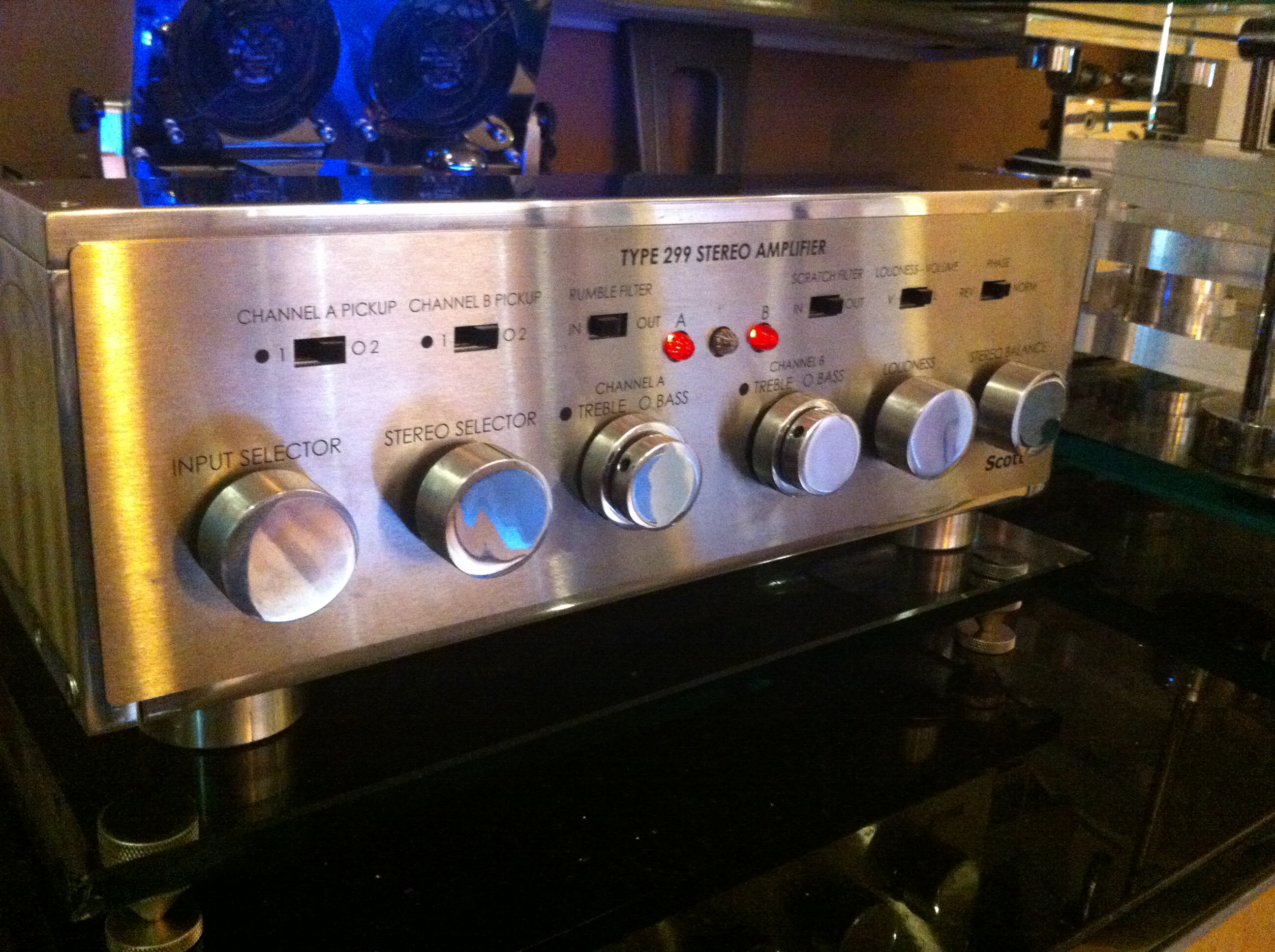
Rivernuggets Thanks for the compliment, here is pic of front / knobs you asked for. They are just 13/8 in. aluminum I cut , drilled and put a set screw in and polished. Ken
-
Thank you for the compliment, It took about 5 months of weekends on an off. The hardest part was learning how to polish the aluminum its a dirty job and takes a lot of time, thank goodness for UTube ! the rest was just cutting and taping the aluminum. a little tough with just normal tools at home, but relay not that big a deal to do. The face plate I had the lettering silk screened buy a place in NY. KEN
-
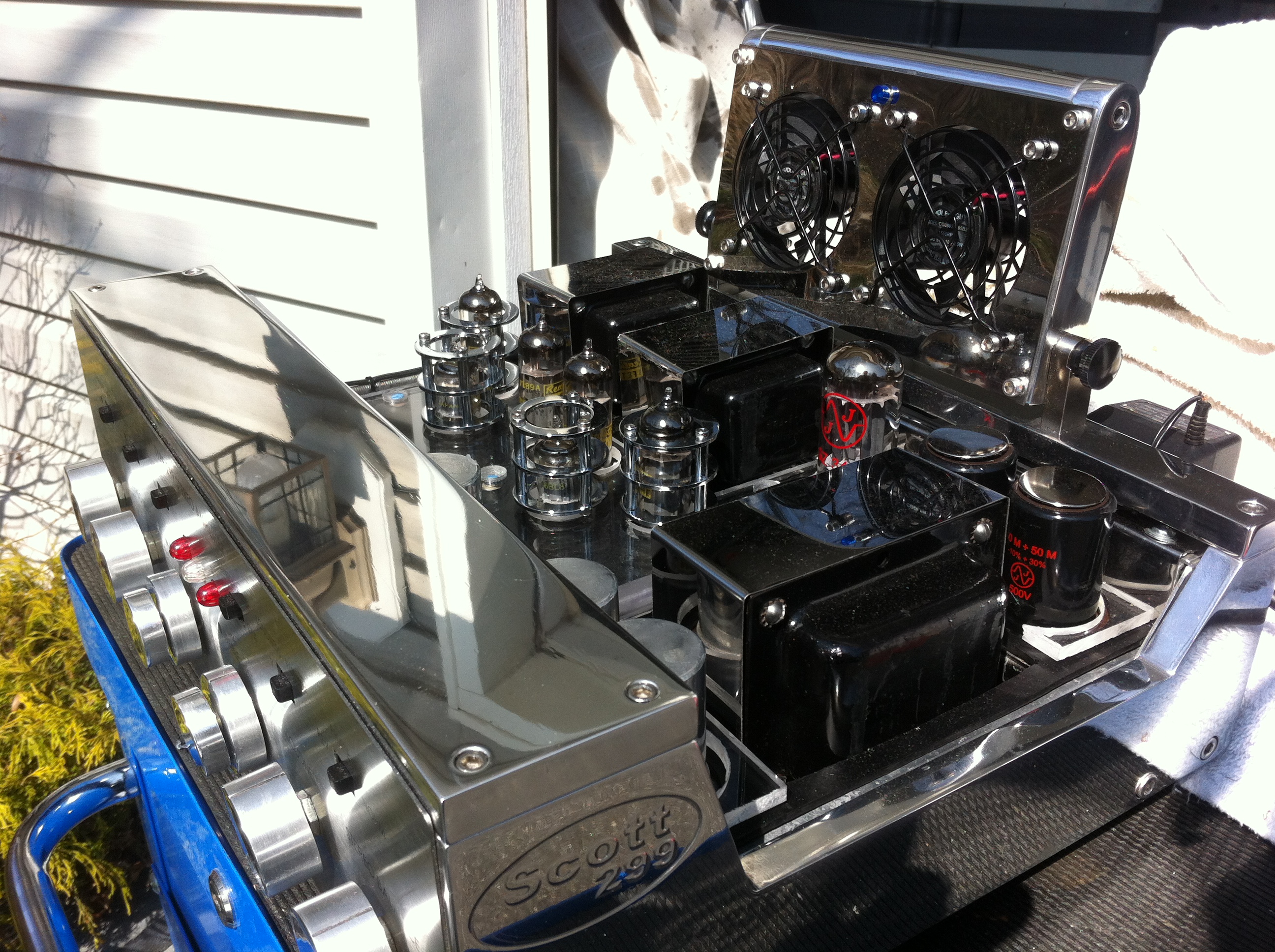
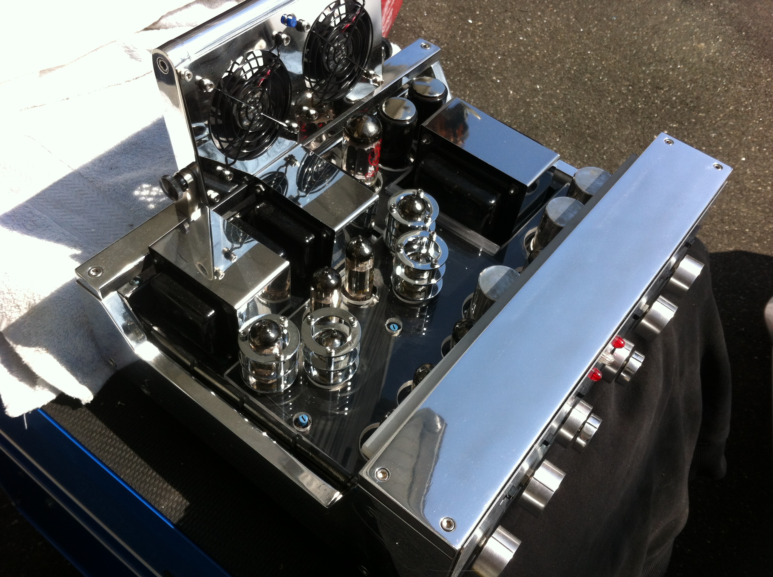
The fans are 3in and make almost no noise, Nothing that you can hear even at the lowest volume when playing something. Thank You for the complement , Ken
-
Thanks , No when I first got it and had the guts rebuilt, before I did the case I didn't know enough to mod it, I am now just staring to think about that. If you or anybody have any ideas I appreciate hearing about it. Thank You for asking Ken
-
.
-
This is my Scott 299 amp completely rebuilt, with a custom case I made of 1/2 in aluminum and some roll stock for knobs and feet. I made the fan case out of same materials. this build was before I built my matching Diy turntable also posted on Klipsch diy turntable forum. Video on YouTube go to DIY Turntable Scott 299 amp
-
.
-
Thanks , im trying to load more pic, having a hard time at it, The hinges I used I took from a computer monitor. Very strong and stop and hold in upright position just used lock nuts and better hardware ken
-
Yes im trying but only have phone camera right now I made a YouTube video with turntable and scott amp quality is Very poor but you can take a look (DIY Turntable Scott 299 amp) Thanks Ken
-
Klipsch Hersey ll
-
Klipsch Hersey II
-
kennyno joined the community
-
This is my DIY turntable made of 1 in. acrilyc and aluminum I used a pro -ject tone arm and a Shure cartiage I built a glass cover and base of 3/4 and 1/2 in. glass. On / off is controlled by remote so no wires anywhere. I use a Scott 299 tube Amp completly rebuilt with a custom made base and frame made of aluminum and two cooling fans. And off course a pair of vintage Klipsch speakers with custom built stands to get that great tube sound. Thank You KEN \