Yasnyi Sokol
-
Posts
28 -
Joined
-
Last visited
Content Type
Forums
Events
Gallery
Everything posted by Yasnyi Sokol
-
Klipsch RF7 (old version) crossover modification
Yasnyi Sokol replied to Yasnyi Sokol's topic in Technical/Restorations
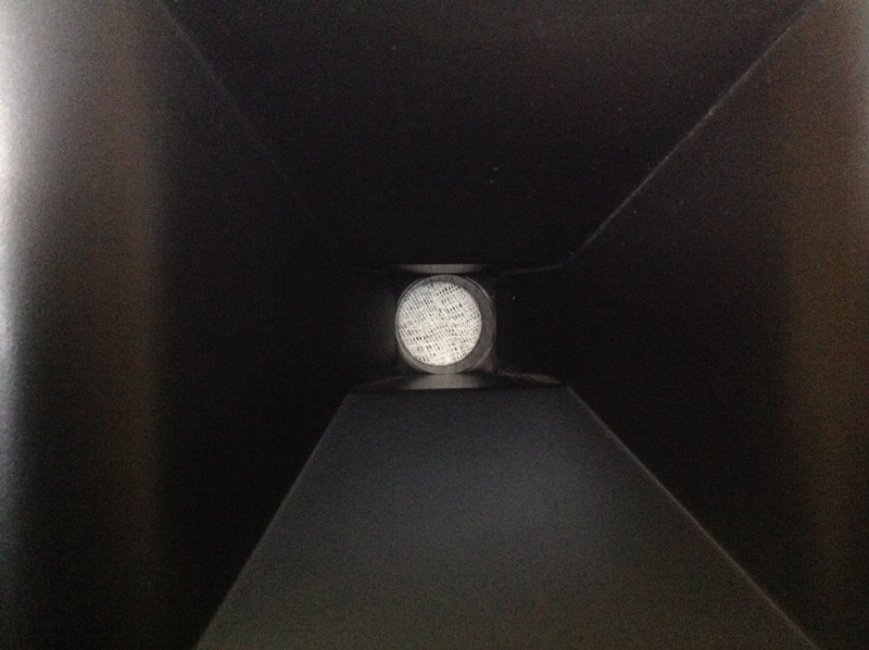
The final mesh size is about 1 mm. This was selected after comparing different meshes. I didn't try foam, only soft tissue around the hole, which I didn't like, and also it did not look cool -
Klipsch RF7 (old version) crossover modification
Yasnyi Sokol replied to Yasnyi Sokol's topic in Technical/Restorations
Hi, Finally, I made few records, which could probably give an impression how the modified speakers do sound... It is dificult to record speakers at home, but at least something than nothing. Mics are Rode M5 stereo pair, see www.rode.com/download/m5-mp_manual.pdf https://www.dropbox.com/s/6n2pqctf27dl4cv/Elvis_From%2024_96%20played%20as%2044100_16.wav?dl=0 https://www.dropbox.com/s/enl41vb92d8idht/Carmen_from_LP_to_44100__recorded%20as%2048000.wav?dl=0 https://www.dropbox.com/s/4668ui2t4agiu0r/Rimsky-Korsakov_from_192_played%20as44100_recorded%20as%2048000.wav?dl=0 Each mic was placed 80-90 cm from each speaker, and at the same height from floor (roughly at the middle between the horn and the top LF driver). Such position reduces slightly bass and midbass, but eliminates the room effect. -
Klipsch RF7 (old version) crossover modification
Yasnyi Sokol replied to Yasnyi Sokol's topic in Technical/Restorations
The latest version of schematic is in post#34. -
Klipsch RF7 (old version) crossover modification
Yasnyi Sokol replied to Yasnyi Sokol's topic in Technical/Restorations
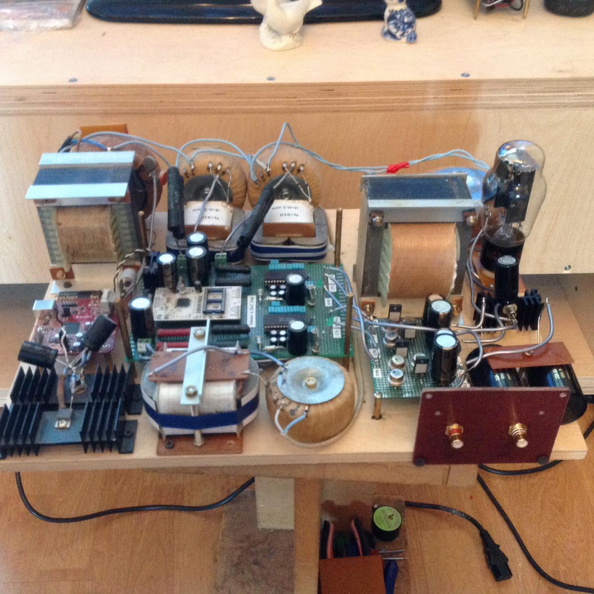
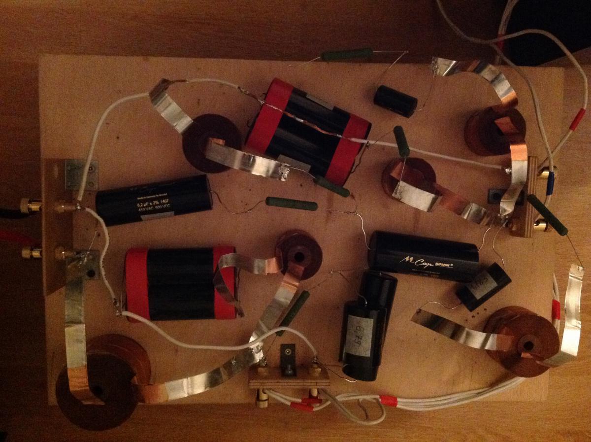
Hi, all, InVeNtOr, thank You for the information. Actually I saw Your upgrage before i started, also there must be a video somewhere on Youtube about plastic horn modification. My friend used to do that and he thinks this is a must be for RF7 plastic horn. As for myself i am so happy with the result that don't want to change anything already. I guess one can make better speakers, but that will be another story. We tryed these speakers with rather good equipment: i.e. Lavry gold Dac. My interest is now digital source, and i replaced my old Weiss Minerva 1394 board based dac (updated with 1853 chip, blackgate caps etc) with simple TDA NOS 14 bit 1540 selfmade dac and like it very much. Will play soon around 1541 just to compare with 1540. These black caps on the photo are all BG FK type and that really makes sense to the sound. Good luck to everybody, hope someone would follow my modification to RF7 some day!
-
Klipsch RF7 (old version) crossover modification
Yasnyi Sokol replied to Yasnyi Sokol's topic in Technical/Restorations
Hi, all, Some recent updates. I stay with this crossover for a long time already and want to say i like it. But if someone decide to repeat my modification I would strongly recommend Mundorf silver oil caps on the high pass of the scheme (8.2 and 15 uf). I have compared both and found SIO much and much better. These are really true high end caps and i could not expect how much they outperform regular Mundorf Supremes!! Regular supremes are the waste of money compared to SIO. Less resolution, less dynamic. Yes, they are detailed, but that is not that details which come from the real resolution. Also regular supremes add some touch i felt always with them. SIO must be trained for about 200 hours to break in. I used a simple scheme with amplifier and load resistor to cook them. I also compared SiO s to not known widely Rike Audio S-caps. These caps are very open and transperant. Very impressive, too. Even more dynamic than Mundorf silver oils. But they add some coloration. Overall, Mundorf SIO give more balanced and deep presentation, so i left SIO caps. Probably, Rikes could be used for bass or mids very well. -
Klipsch RF7 (old version) crossover modification
Yasnyi Sokol replied to Yasnyi Sokol's topic in Technical/Restorations
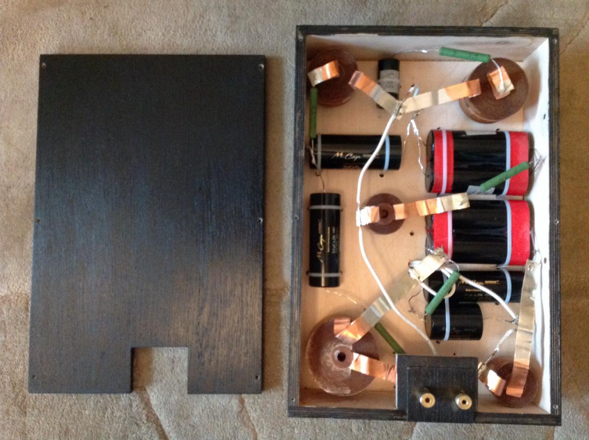
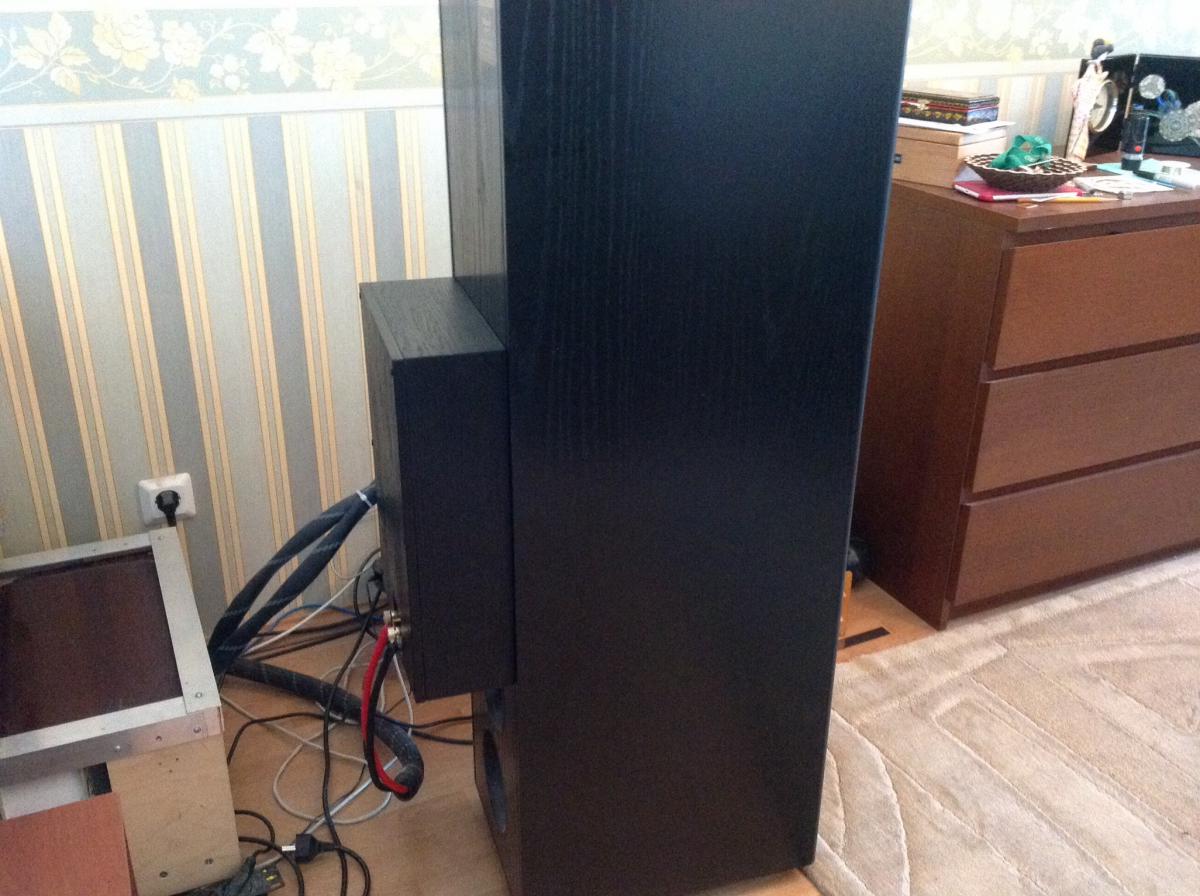
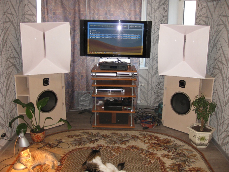
Hoping the project is finished. The box is hand made: plywood 10 mm and natural oak 1.5 mm.
-
Klipsch RF7 (old version) crossover modification
Yasnyi Sokol replied to Yasnyi Sokol's topic in Technical/Restorations
deleted -
Klipsch RF7 (old version) crossover modification
Yasnyi Sokol replied to Yasnyi Sokol's topic in Technical/Restorations
I think the 3rd order is still better than my 1st order. So fix it for a while as follows. Tweeter has the mesh #20 instead of original.
-
Klipsch RF7 (old version) crossover modification
Yasnyi Sokol replied to Yasnyi Sokol's topic in Technical/Restorations
Now i am back to 3rd order to make comparisons. Look at this size
-
Klipsch RF7 (old version) crossover modification
Yasnyi Sokol replied to Yasnyi Sokol's topic in Technical/Restorations
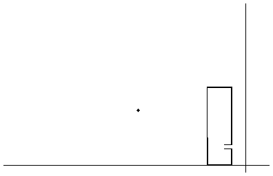
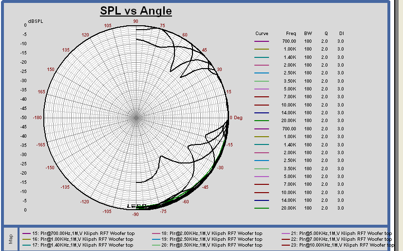
Placing the horn close to wall could unbalance the responce. Only bass notes will be amplified by "big horn". Look at that: The same applies to Jensen corner horn with Altec 416 driver: My friend has built the last one and here are his measuments in real room (which is also quite small). His room has more complex wall behind the speakers than one used in the simulation, which might be also the reason why the plots differ. http://photo.qip.ru/users/yras/4142238/101865539/#mainImageLink http://photo.qip.ru/users/yras/4142238/100875270/#mainImageLink
-
Klipsch RF7 (old version) crossover modification
Yasnyi Sokol replied to Yasnyi Sokol's topic in Technical/Restorations
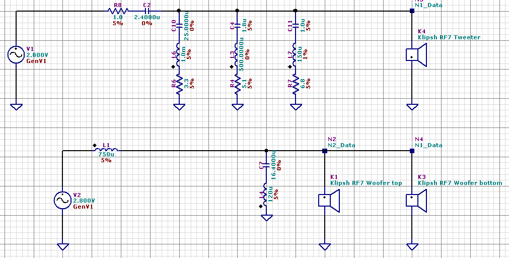
Continue the story. I compared two meshes on compression driver, #20 and #40 (the number of holes per inch), and found #20 sounds better for me. Mundorf silver/gold/oil 2.2uf caps have arrived. At the moment the crossover is as follows. 2.4uf cap is 2.2 uf mundorf silver/gold/oil plus 0.22 uf tin foil multicap RTX. All other caps are Mundorf supreme. All coils are Jantzen wax coils.All resistors are jantzen MOX super resolution.
-
Perhaps, Your could find interesting to read my small research on rf7 crossovers here https://community.klipsch.com/index.php?/topic/156444-klipsch-rf7-old-version-crossover-modification/
-
Klipsch RF7 (old version) crossover modification
Yasnyi Sokol replied to Yasnyi Sokol's topic in Technical/Restorations
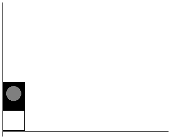
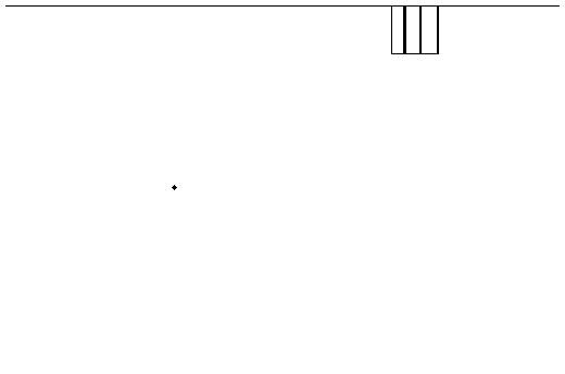
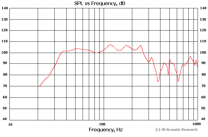
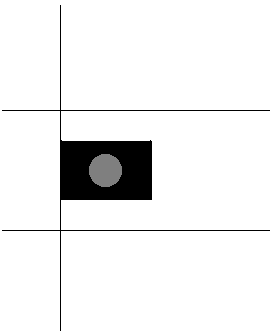
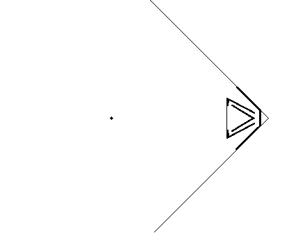
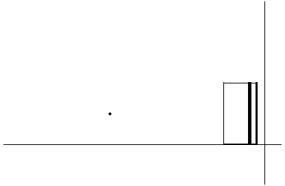
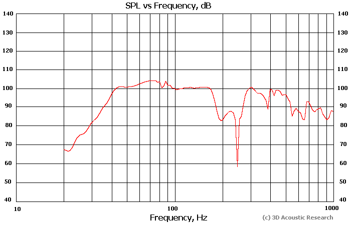
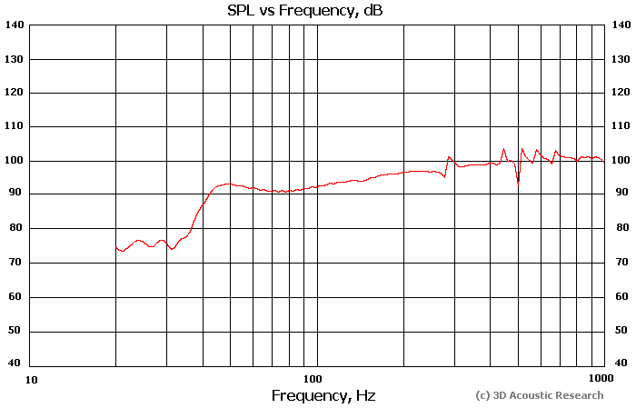
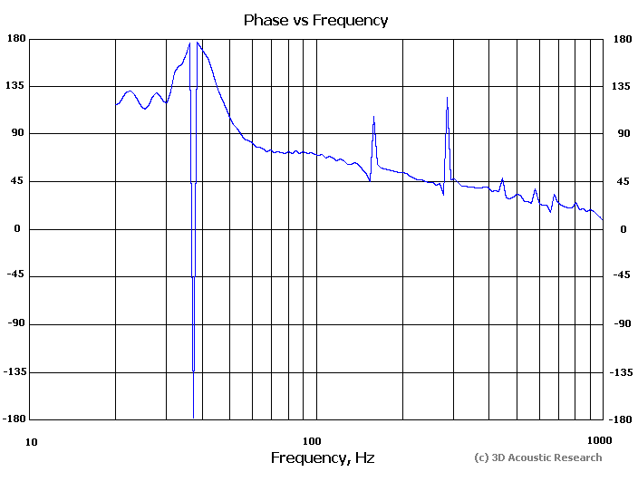
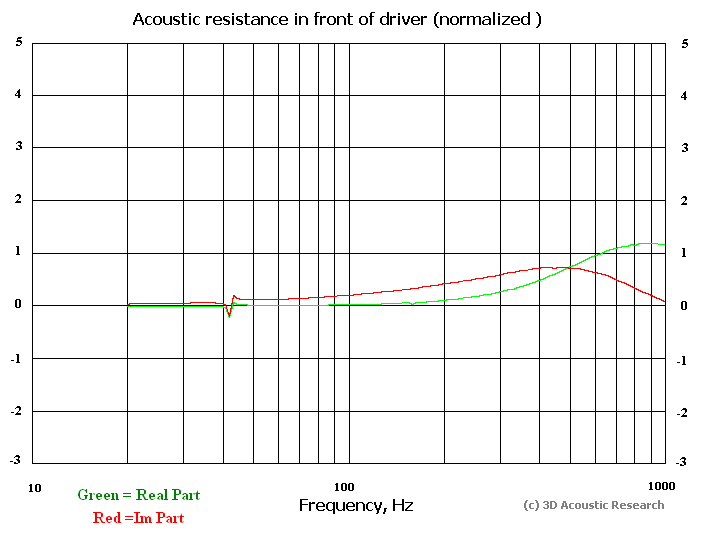
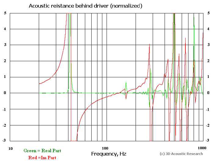
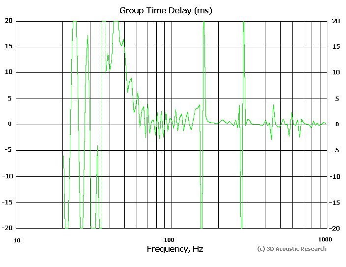
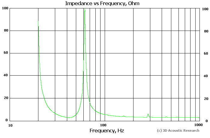
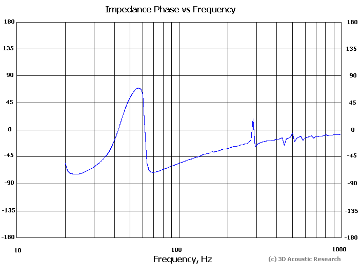
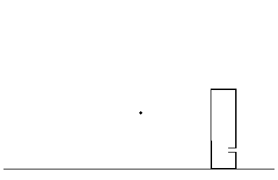
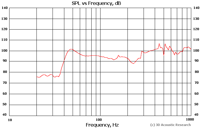
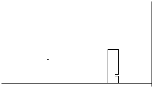
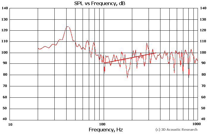
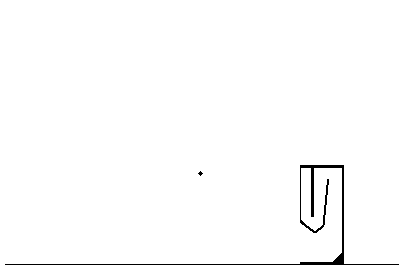
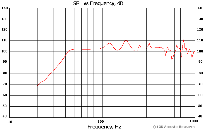
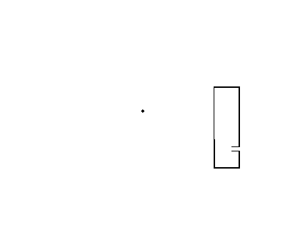
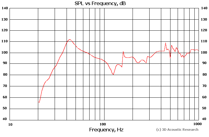
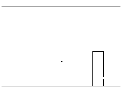
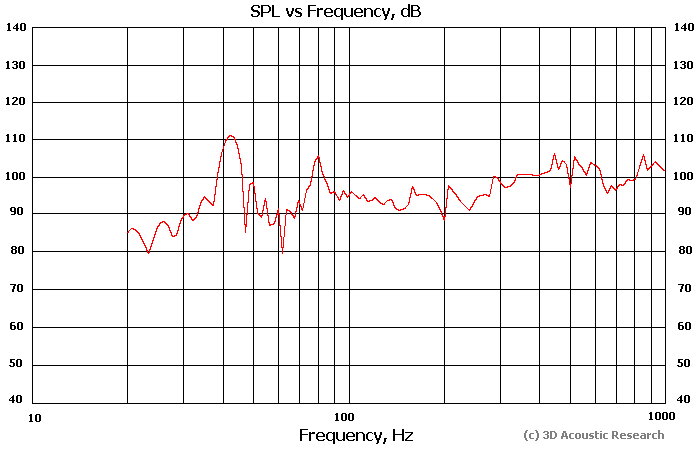
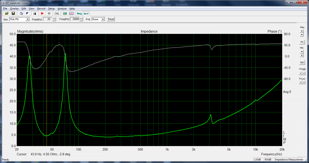
That could make some possitive effect, thank You for the idea. Meanwhile I am waiting for my best caps from Mundorf, let's play with enclosure of RF7. Bass Reflex or Back Loaded Horn? TypicalT/S parameters (they are published) are as follows: Fs =31 Qes=0.22 Qms=11 https://community.klipsch.com/index.php?/topic/24048-diy-project-k-1089-av-rf-7-copper-woofer/ These make one think why they use bass reflex enclosure for the drivers? It looks like the drivers are more suitable for horn load. I put parameters of bass drivers in 3D acoustical simulator (3D Acoustic Research project I take part in, the last version of software is not published yet). The idea behind that program is to solve the wave equation in 3D domain for given electrical and mechanical parameters of the drivers. For simplicity I use single driver with same parameters (double Vas and Sd, half Re). For acceleration CUDA is used with powerful graphic card. The element size of numerical grid is 1 cm. Equivalent parameters Re =3.02 ohm Sd =0.0720 sq.m Fs=31 Vas=212 l Qes=0.22 Qms=11 Here are some results. The BR is tuned to around 43-44 Hz similar to real speaker of Klipsch. Black point shows the mic position. Open space Here the baffle-step effect is presented, and also the enclosure is too big for given Qts. This next plot is real impedance measument of two woofers in parallel (the simulation doesn't take into account the losses due to dampening material inside the volume, that's why impedance peaks are smaller). Also I have the second peak close to 60 Hz instead of 70 Hz (i didn't measure T/S parameters for my own drivers, just took the data above from the given link). Half space (on the floor) Floor and ceiling Close to wall A lot of bass. But ...do You like this? Penal room (all reflecting walls except the rear to the listerner which is open, or in other words, perfect wave absorption behind the listerner. In this particular case it makes big reverberation time and low absorption in bass region as follows from the plot) (in the last case the real energy level in bass region would be determined by the amount of energy absorption in real room) One consideration from that is: the driver placed too high above the floor generally lacks from the midbass region due to reflection from the floor. This effect is reduced when the mic is far to the speaker. Carpet is better than rigid floor surface. The last picture shows the effect still remains in real room. Partially also due to low Qts of the driver. I guess that engineers of Klipsch tryed to get most possible low bass with the bigest possible volume of the enclosure. Compare that with real measurements of RF7 which were published in my first posts. The next consideration is to replace BR with BLH. Horn has big exit area along vertical, and reflection from the floor from numerious point sources at the exit is partially compensated. This improves midbass region. Floor acts as a part of the horn. On the other hand, bass horn is difficult to build, the exit area is always a compromise as it is less than the wavelength, and the reflection of back wave inside the horn produces ripples, which are reduced for half space radiation, quarter space etc. A lot of literature on that. BLH is also tricky as one should take into account both frontal radiation from the driver and from the horn with time delay. Here is an example of BLH for RF7 drivers (two in one enclosure). Quite simple as it consists of almost plain elements. Back loaded horn (width is about 45 cm, height 1 m, depth about 40cm) on the floor. Lets "listen" By this i mean that I can calculate FIR (finite impulse resosponse) at the mic position. I take a test wav file, split it into LF and HF parts (HF is original minus LF obtained with a digital filter, Hamming window function is used for filtering with -42 dB outside the main frequency region). Then the LF part is convolved with FIR from 3D simulation. The result is summed with original untouched HF part, taking into account the volume level of both. So, bass comes from the enclosure, while HF is "sonically ideal". This can be considered as I "did nothing to real wood work but still is able to listen" to the result The comparison is here (two WAV files). LF is filtered at 800Hz. TIme shift between LF and HF is zero. (When crossed at at 250-300 Hz the delay 3-5 ms for HF to compensate the group time delay of bass section sounds better). http://mab.to/ZFvb7liIs Forgive some sibilants (they come from numerical simulation). Bass reflex has typical sound of bass reflex, the horn has typical "tabouret bass". .
-
Klipsch RF7 (old version) crossover modification
Yasnyi Sokol replied to Yasnyi Sokol's topic in Technical/Restorations
I think that most unpleasant peak comes from the dust cap. Damping the basket wouldn't help it much. Some resonances across the woofer may go away, of course. -
Klipsch RF7 (old version) crossover modification
Yasnyi Sokol replied to Yasnyi Sokol's topic in Technical/Restorations
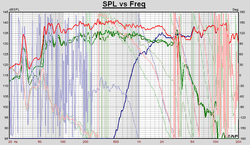
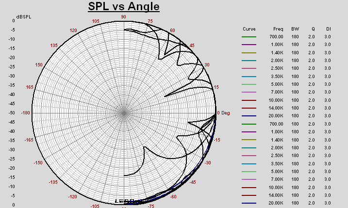
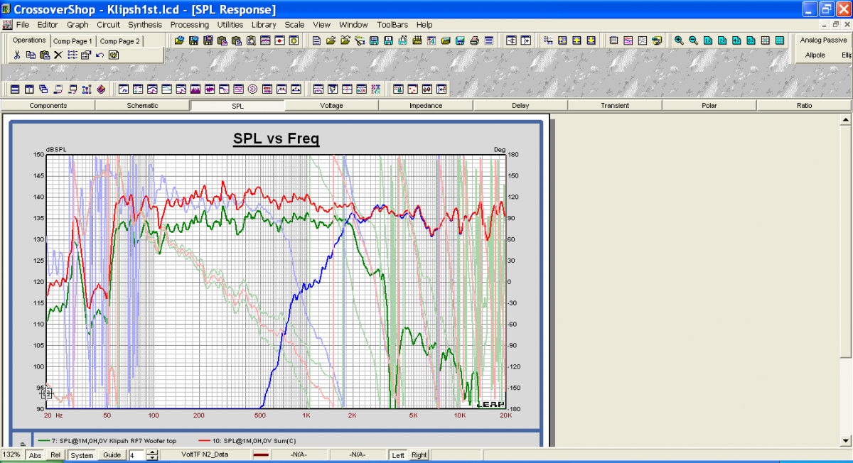
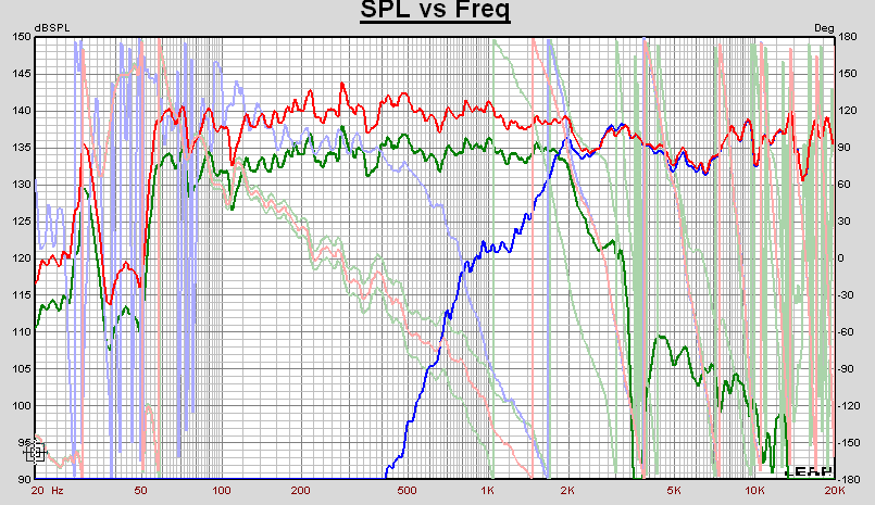
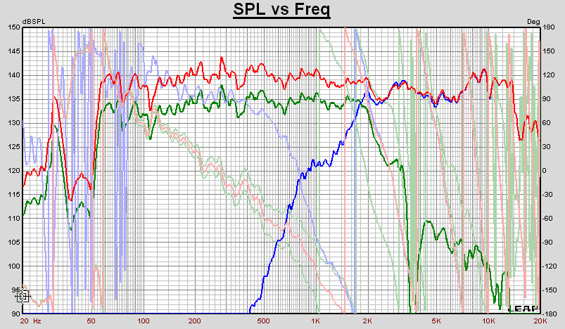
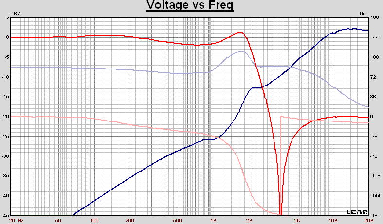
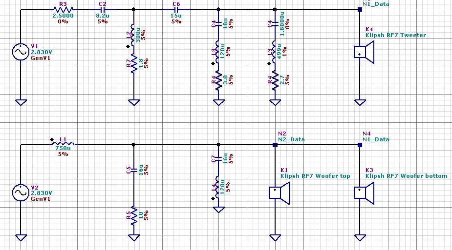
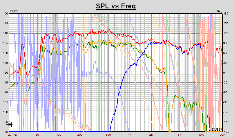
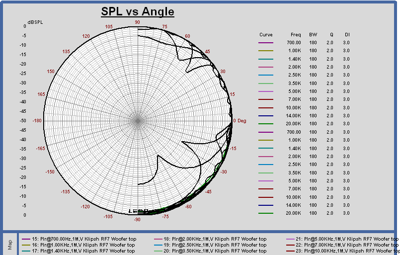
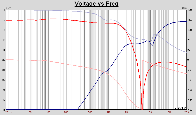
Agree with that. The second problem of 3 kHz peaks is that they come from two point sources separated with the distance of 28 cm (two LF drivers). 28 cm is a wavelength at 1.2 kHz, while 3 kHz is already almost two wavelengths. So the vertical angle phase interference is very irregular, next plots show the sum of two woofers and the tweeter in Leap at 1 m distance, at the middle between the top woofer and the tweeter. Original Klipsch crossover These speakers are a lot of compromises . I expect that reducing this unwanted energy at 3 kHz from two woofers also improves the directivity patern. Considering the design with 1 cap and main notch filter on the tweeter resonance one can also easily add the second cap after the notch. It would be already 3rd order of course, but with main notch filter outside of working region. These is calculated for the tweeter without the mesh. It doesn't differ much from the "1 cap-version", but at low end the tweeter is filtered more. At the moment I put stainless steel mesh with 1mm cell on the compression driver, think it sounds quite well with 1 cap cross, but haven't measured it yet.
-
Klipsch RF7 (old version) crossover modification
Yasnyi Sokol replied to Yasnyi Sokol's topic in Technical/Restorations
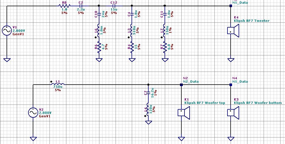
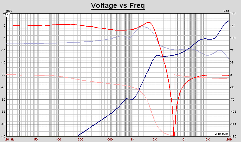
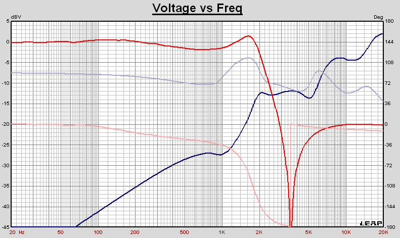
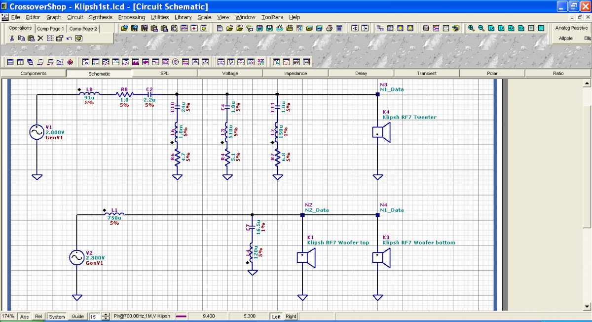
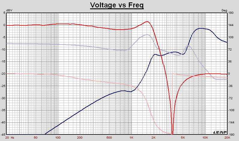
Hi, Robert, There are voltage curves in posts #6 and #7. Blue line is for tweeter. I added it also for the scheme in post 17. For modeling I use Leap CrossoverShop with impedance measurements of the drivers first, of course. Otherwise it wouldn't coincide with acoustical measurements. Original design of Klipsch is as follows: The difference between the shelf 2-5 kHz and 1 kHz is slightly better for 1st order with notch filter. The 3rd order outperforms bellow 800 Hz, which is already -15 dB. Of course, it is always a question of compromise.
-
Klipsch RF7 (old version) crossover modification
Yasnyi Sokol replied to Yasnyi Sokol's topic in Technical/Restorations
Thank You, guys! Think the coil on the top still slows the sound, not so agressive and sharp as I would prefer! The coil has gone and the test Xover now is as follows (1uf +0.15 mH + 6.8 ohm do some job at 10-12 kHz). If one puts a soft cloth inside it is OK, but without it there is still too much energy on the top.
-
Klipsch RF7 (old version) crossover modification
Yasnyi Sokol replied to Yasnyi Sokol's topic in Technical/Restorations
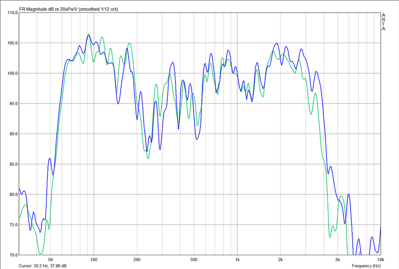
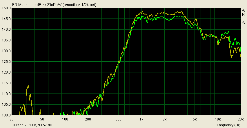
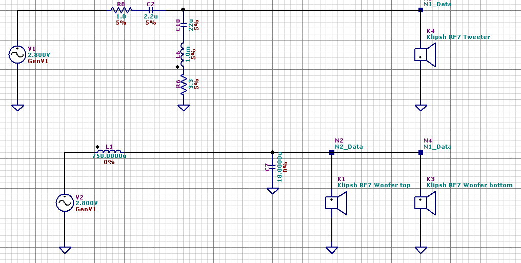
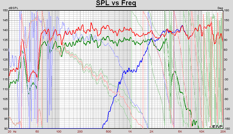
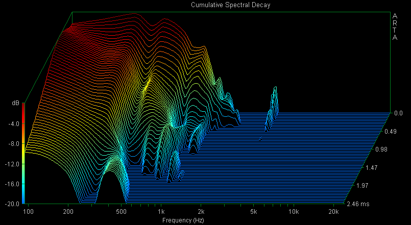
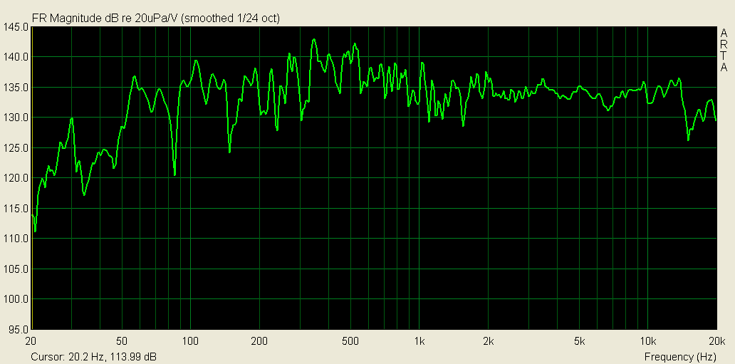
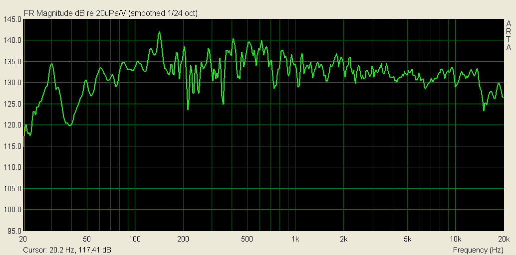
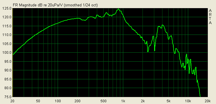
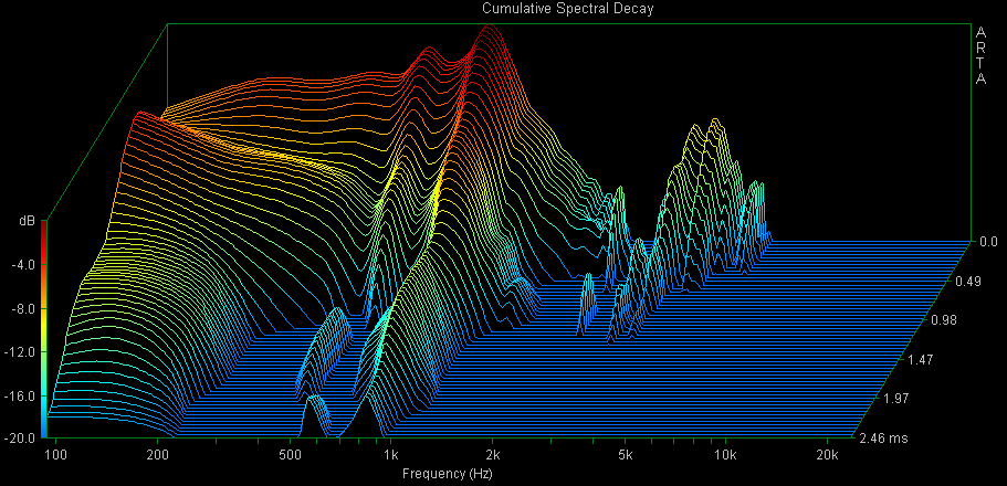
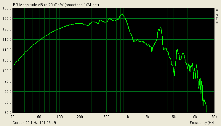
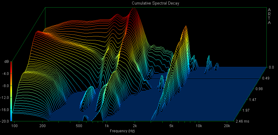
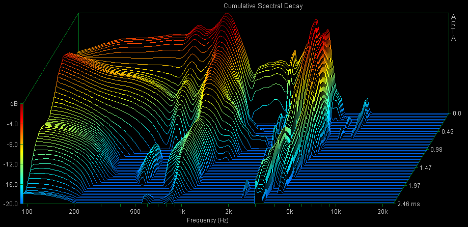
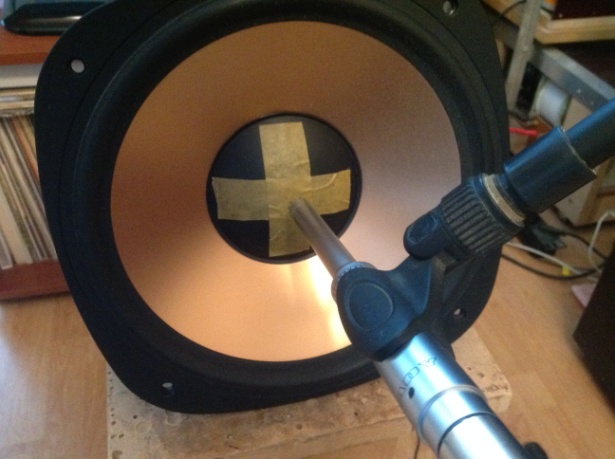
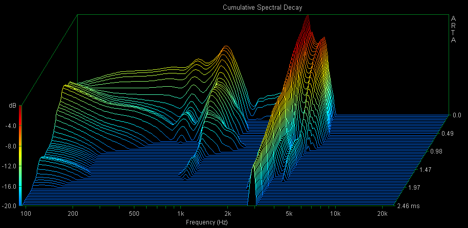
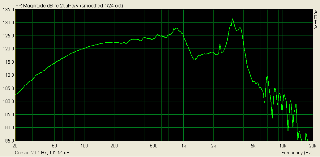
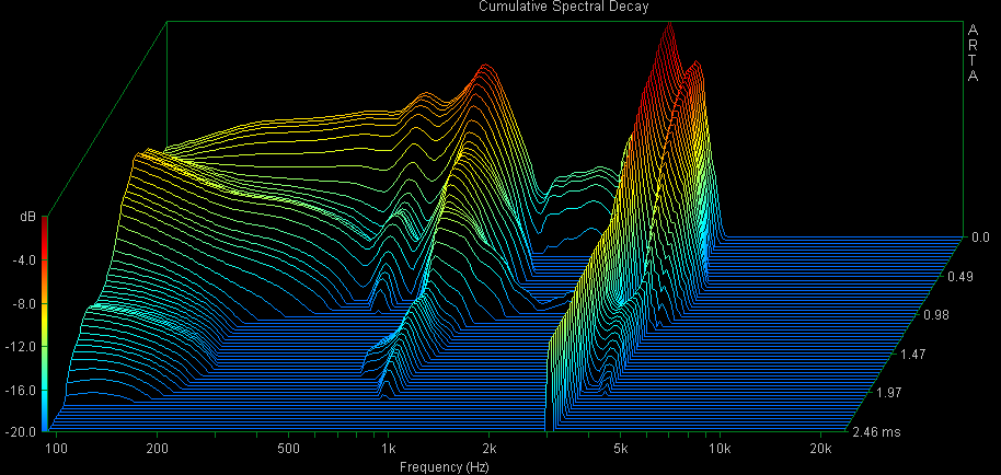
Effect of mesh on compession driver Some folks said that without mesh the sound becomes better. And its role is reduced to protect the driver from dust etc. I tryed to check that. Technically the mesh screen is an acoustic resistance which slightly damps the diaphragm. Here are some measurements from a distance close to RF7's horn with and without mesh on the driver. Green is no mesh, brown is with mesh. The measurements were done at different time with different input level, so absolute value is not important. More important is that without mesh the response is higher at top frequences which seems to be predicted. The waterfalls show the effect on diaphragm resonances. With mesh: Without mesh: One can see that in most important region 2-10 kHz wihout mesh the peaks are slightly reduced, which is quite interesting and promissing. If one is interested to compare the driver in RF7 with other comression drivers I can bring here the measurements of B&C de200 in original horn of Zingali Home Monitor and radian 475B in some horn: de200: radian475B: This may give an insight to someone's consideration whether the klipsch driver is better on not . I beleive from these measurements the klipsch driver is quite good one. Looking at these measurements i decided to build a test crossover for driver without mesh. The first one was made similar to the first modification i posted above with the 3rd order filter. However something strange happened to the sound. I heard the improvements and good articulation of vocals, but overall it was a feeling the driver is not very clean, perhaps due to something happening at top frequences. Maybe the tweeter sounded faster than mids. I tryed to put additional notch filter to reduce 10 kHz region, in next version a small input coil but it was not full satisfaction. The next crossover was made similar to simple 1st-order: This version sounds interesting and now i need to accept whether it is enough of highs for me. I found that the effect of small coil on the top makes the sound of the tweeter cleaner and consistent with mid drivers. Otherwise, if i don't finally like that sound the mesh will come back, of course. I counted the threads of the mesh (btw, not so easy to do ). There are about 76 threads per inch. Some meshes can be found on ebay even from copper or brass, from the numbers in the range #40-80, that covers about the same cell size as in original one. Perhaps it would be possible to use an intermediate solution with mesh, but with sligtly bigger cells. I understand that engineers from Klipsch know what they are doing when use the mesh. But it is interesting to look at the things with my own eyes. A friend of mine also having the RF7s asked me whether it is possible to do most simplest version of X-over without any notch filters and for the case without mesh (he also deleted it). He put soft cloth material instead of original mesh and says it is very pleasant sounding. Here is the calculation of 1st order X-over for his case (to be exact with no mesh), but i didn't listen to it myself.
-
Klipsch RF7 (old version) crossover modification
Yasnyi Sokol replied to Yasnyi Sokol's topic in Technical/Restorations
Thank You for Your responses! -
Klipsch RF7 (old version) crossover modification
Yasnyi Sokol replied to Yasnyi Sokol's topic in Technical/Restorations
deleted -
Klipsch RF7 (old version) crossover modification
Yasnyi Sokol replied to Yasnyi Sokol's topic in Technical/Restorations
deleted -
Klipsch RF7 (old version) crossover modification
Yasnyi Sokol replied to Yasnyi Sokol's topic in Technical/Restorations
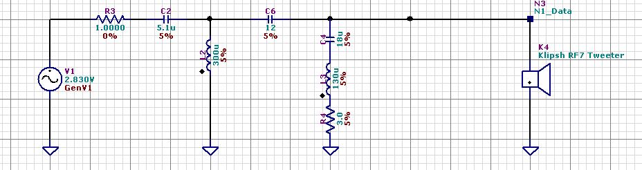
Simplicity Let's look again at tweeter equalization. What I didn't like in 3rd order crossover is the number of elements plus LCR filter working in the wide range for tweeter equalization. A lot of elements for the signal to pass through. This can be also understood considering the decrease of impedance, as some amount of signal current has to pass through LCR filter instead of the tweeter. Can we do tweeter equalization more simple? Here is another method: first order plus damping of the main tweeter resonance. One cap on the signal pass, which can be selected from top level caps due to its small value. One can say that first order crossover is not good for the compression driver. However, look at the voltage graph and tweeter spl and compare them to the graphs in upper post. The simple version has similar sharp roll-off for tweeter which is not bad compared to the 3rd order design. The other points are: Klipsch-analog design has (i) two caps on the pass plus coil (3rd order). (ii) LRC filter in the wide range 1-5 kHz to equalize tweeter. Alternative X-over has (i) only one cap on signal pass (ii) narrow LCR filter tuned to 1 kHz (main tweeter resonance), which works almost outside the working range. I didn't make that exact crossover but one can try. Notice that 5 kHz peak still remains, as it is present in the original driver.
-
Klipsch RF7 (old version) crossover modification
Yasnyi Sokol replied to Yasnyi Sokol's topic in Technical/Restorations
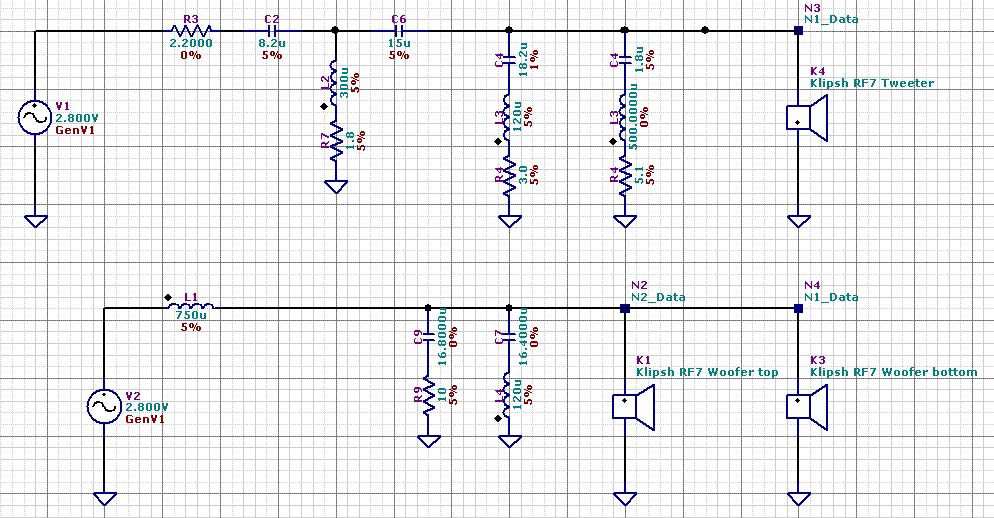
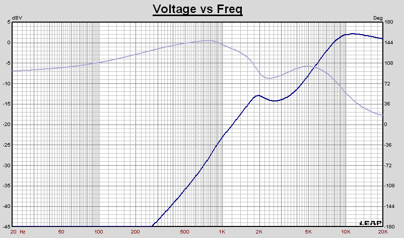
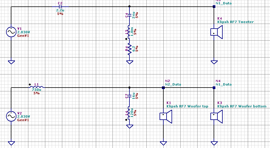
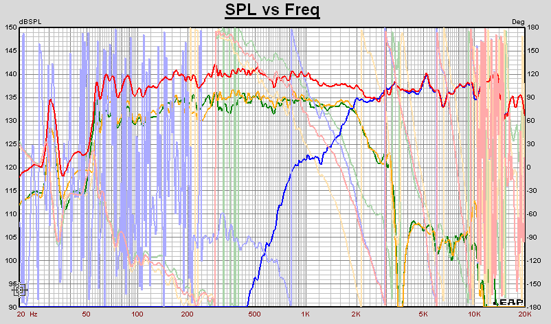
New crossover (original drivers). So, here is another version of X-over for RF7. It was designed together with my friend (he asked not to give his name). First, the notch filter at 3.2 kHz, and some mods with 16 uf-10 ohm on the woofers to better match in phase with the tweeter. The idea of tweeter crossover was taken close to original Klipsch design. 18uf plus 0.12 mH reduce the range 1-5 kHz to flatten the tweeter (this is not the last opportunity, more on that later). We also increased the caps to 8.2uf and 15 uf based on Leap calculation, measurements and listening tests. 1.8 uf and new coil 500 uH slightly reduce peak at 5 kHz, which is also present in original klipsch sound. The input resistor on tweeter can be adjusted arround 2.0-2.4 ohms up to personal taste. bass/midbass waterfall Room SPL 1 m Room SPL 2m All coils are Jantzen Wax (12 awg 750 uH on bass and 14 awg others). Caps are Mundorf supreme on bass with 120 uH, 16 uf with 10 ohm is Jantzen cross cap. 8.2 uf on tweeter is also Mundorf supreme. 15 uf was made by simple 12 uf Janzen cross cap by-passed with Fostex 3.3 uf cooper tin foil. 18 uf was also jantzen cross cap. Later I ordered all caps Mundorf supreme, but already modified the tweeter. That is another part of the story. At that level I enjoyed much new crossover. It has more resolution and is more transparent. Direct comparison to original crossover showed it is cleaner and more natural to my taste. Slightly darker on the top, but it is to personal choice (one can change the input resistor).
-
Klipsch RF7 (old version) crossover modification
Yasnyi Sokol replied to Yasnyi Sokol's topic in Technical/Restorations
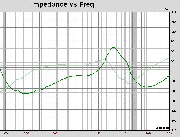
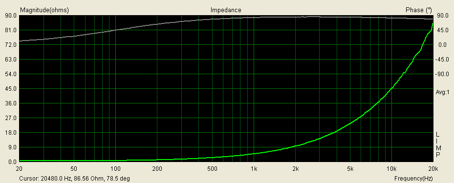
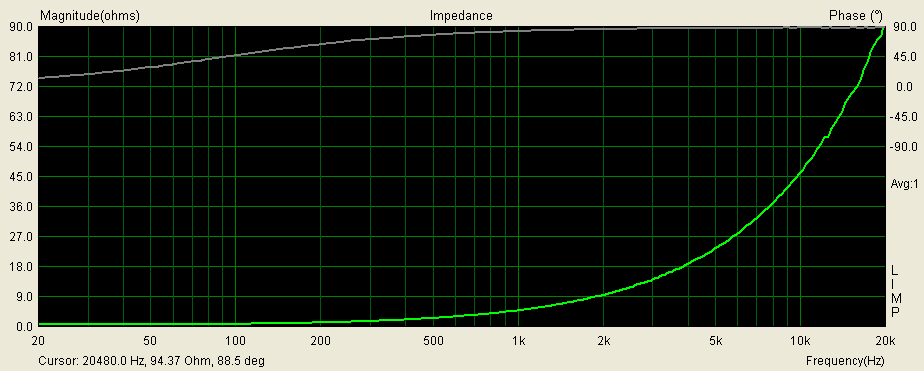
Before I continue I would like to show some measurements of ribbon coil. Some say ribbons have huge capacitance. Is it why sibilants appeared? No. One graph is original klipsch (they say it is 0.75 mH but measuring two I found one is close to 0.75 mH but the second is slightly less). Another graph is jantzen wax 12 awg. Looking closer at phase one can see that jantzen is exactly with 90 degree phase with no appearance of capacitance effect. Klipsch coil starts to slowly reduce phase at the top end. Not to much, but this is to show that jantzen ribbon is almost perfect coil. Klipsch original coil Jantzen ribbon coil
-
Klipsch RF7 (old version) crossover modification
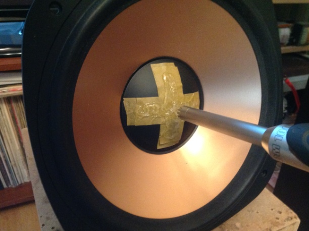
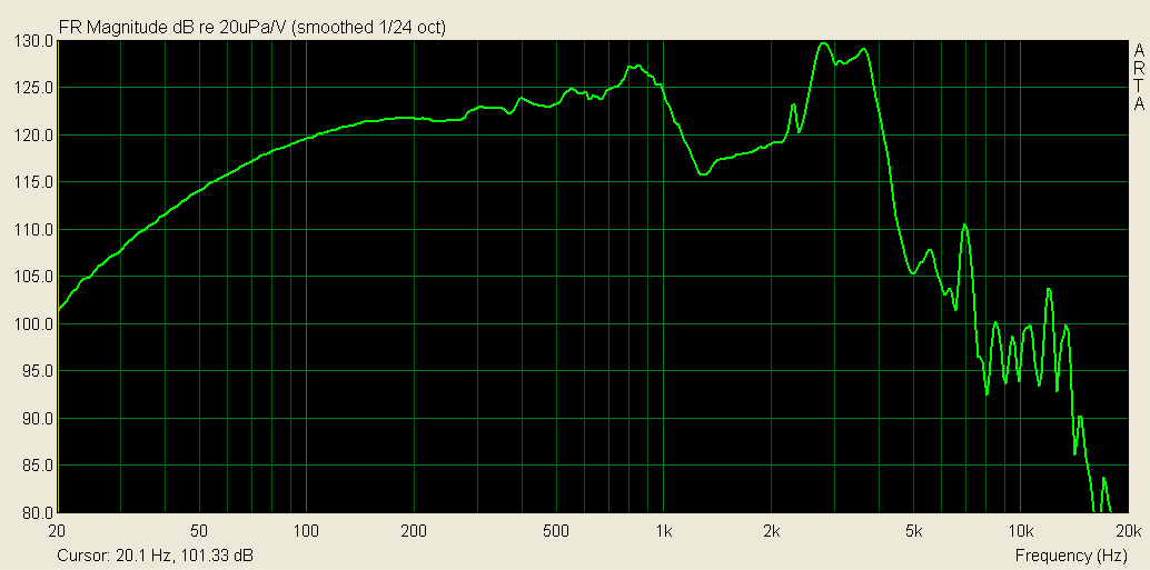
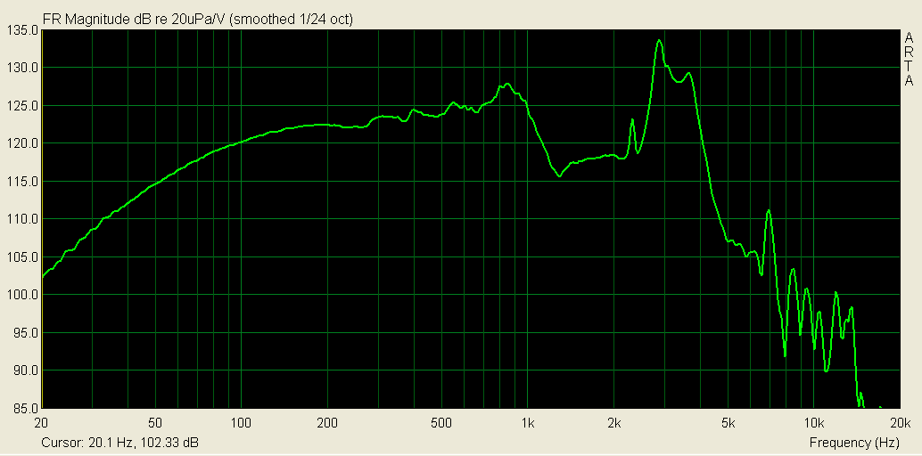
Yasnyi Sokol replied to Yasnyi Sokol's topic in Technical/Restorations
There were two options (i) damp it mechanically (ii) damp it electrically in the X-over. First I was interested where it comes from. The first idea was to paste some absorption material (paper, leather etc) on the back side near the driver cone edge, at the place where usually resonances of hard cones appear, that is about at 3/4 of radius). The driver was taken out and the cone was measured near the edge, between the edge and the dust cap, and at the axis, that is in front of dust cap, at about 1 cm. At the edge At the middle between edge and dust cap at the axis This shows that the main contribution to unpleasant 3 khz peak is due to the dust cap. I cannot fix the problem with damping the cone on back side. Some good idea was to delete the dust cap. I was told by a friend that usually helps much and "opens the sound". But I was afraid the point of cone break up will move down and I would not be able to fix it with two-way crossover.. The dust cap improves the rigity of the cone, without it the cone will bend easer. But You can try to remove dust cap. Here are also some measurements with damping (scotch paper of 2 and 4 layers, and silicon on the paper). Doesn't help really. Moving mass is increased on the dust cap, the peak is increased or becomes wider with damping, but doesn't go away paper 2 layers: paper 4 layers paper 2 layes plus silicon So, the right way was (if one doesn't delete the dust cap) to damp the cone resonance electrically. BTW, the dust cap is made from thin alluminium.