rjp
-
Posts
124 -
Joined
-
Last visited
Content Type
Forums
Events
Gallery
Everything posted by rjp
-
Wow, that's fancy! Too rich for me though. I think I'll stick with the cheap L-pad What is the advantage of a transformer over a resistor as far as preserving fidelity?
-
I need black tissue paper
-
Hi wdecho, As mentioned on Page 1, I presently have L-pads installed just before the tweeter. I understand how they work, and that's why I chose them as my first experiment here. I am very pleased with the results and my conclusion is that L-pads work well in this application. I guess this should come as no surprise since this is what they were designed for. However, I think pzannucci brought up an interesting technical point. For an L-pad to present a constant impedance to the source at any dial position it is necessary that the design impedance of the L-pad match the impedance of the load. Since the load in this case is a speaker, it's impedance is not purely resistive and varies with frequency. This means the L-pad can never be a perfect match at all frequencies (though it may be close enough that it makes no difference that we can hear). (Note: I measured the impedance of my RP-260 tweeters, and the equivalent series resistance (ESR) varied between 8 and 16 Ohms over the frequency range 1KHz to 10KHz. No single L-pad can match both extremes) I'm not sure what the implications of this mismatch might be but it does seem that the introduction of an L-pad at the tweeter must change the impedance the crossover sees at least at some frequencies. So although it works great, I think it is fair to say that the crossover is not seeing the same load Klipsch designed it to see. Does it matter? I have no idea. The series resistor in discussion is before the crossover, so it will not change the load the crossover sees, but will change the HF response of the crossover itself (kind of like having higher resistance speaker cables). So it is also not a perfect solution but for a different reason. I'm not sure how to analyze this. Maybe someone good with PSpice could give it a try? In any event, both methods seem to work and sound about the same to my ears, but I think single Kleenex tissue sounds even better as it seems to reduce mid treble and leave the high stuff unaltered. But tissues look bad in front of my speakers
-
I tried the series resistor method. I measure approximately 1 dB decrease in tweeter output for each 2 Ohms of added resistance. Form my testing with the L-pad I like the level about 2-3 dB down, so I would need 4 to 6 ohms resistance.
-
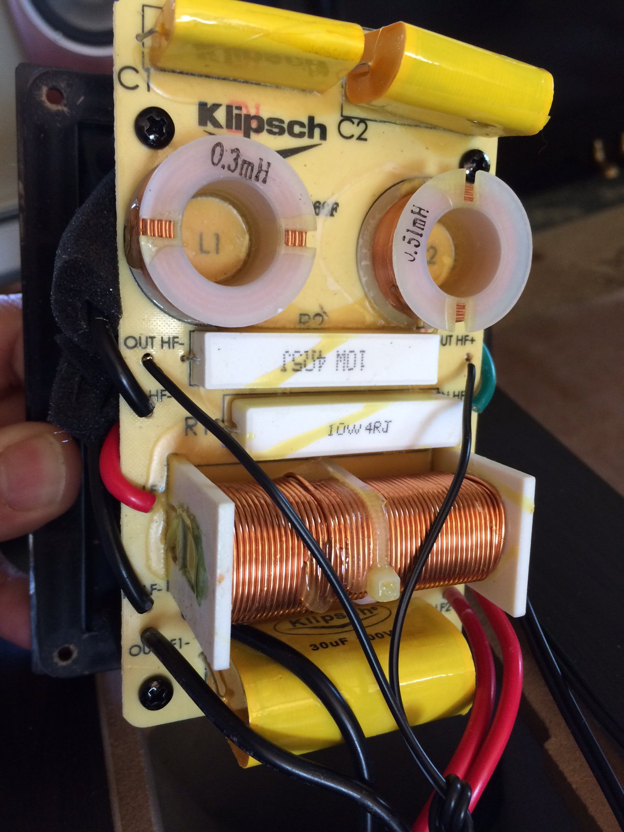
Note regarding the RP-260F crossover posted above. I want to point out that I could not actually see the connections of the wires at the tweeter terminals inside the box, so I cannot say for sure if the HF positive crossover output actually goes to the positive terminal on the tweeter or if Klipsch reversed it. The polarities labeled in the drawing are those stamped on the crossover board itself. Btw, here is a picture. The skinny black wires on the HF Out are from my temporary L-pad experiment. The original Klipsch wires are like the thick black one next to it.

-
Oh, ok. Now I follow. You put the resistor between the woofer post and tweeter post instead of the jumper. Got it. In that case, it would indeed be identical to replacing the existing 4 Ohm resistor with a 5 Ohm resistor in the schematic. There are two things I like about this: (1) It seems to be in keeping with the way Klipsh would have done it. (2) It seems it would have less impact on the crossover frequency since as you mentioned there is no longer any possibility of mismatching the tweeter impedance at the output of the crossover as in the L-pad case.
-
True, it already works fine with the Lpad, but I am eager to learn more about your idea none the less. Clearly Klipsch feels that a single resistor is the way to reduce the tweeter volume as I believe that is the purpose of the 4 Ohm resistor in the schematic, correct? I think that resistor is there for no other purpose than to attenuate the tweeter to better match the woofer volume. Or am I missing something here? I thought you were suggesting to add an additional 1 Ohm to this existing 4 Ohm resistor (which seems like what Klipsch would have done), but from your description it sounds like you are saying to put the 1 Ohm resistor across the tweeter the input posts at the back of the speaker cabinet, or are you saying on the back of the tweeter itself? In any even it is a parallel resistor not series? To make it clearer could you please tell me where in the posted schematic you would put the resistor? Thanks.
-
Not sure I follow your point here. Are you saying a single series resistor is a better solution than an L-pad at the tweeter? If so, would you add this additional resistance to the existing 4 Ohm resistor shown in the schematic?
-
Update: I installed the L-pads and they seem to work as expected. That is, the level of the tweeter goes down smoothly as I turn them. To my ears they still sound just as good so I don't think the pad is reducing fidelity at all. I seem to like them with just a very small amount of attenuation. I would estimate less than 1/8th of a turn from full on. Not sure if these are linear or logarithmic so no way of knowing the attenuation at this point. I had to go into work. Will listen more tonight. So In summary, I would say adding L-pads to the RP-260F tweeters is a viable solution. If I decide to make it permanent though, I'll have to decide where to mount them. I don't want to drill holes. With further listening and measuring I hope to try to quantify the effects on the frequency response better using my "trusty iPhone spectrum analyzer" and white noise generator. Actually, I also have a calibrated signal generator that I could use to sweep the spectrum with CW tones. Then I could just measure SPL. That would be more accurate, but it's also more work to set up. I have all this stuff from radio electronics work but this is my first foray into loudspeakers so I'm trying to learn by asking questions. Thanks for all the great discussion today. Looking forward to more.
-
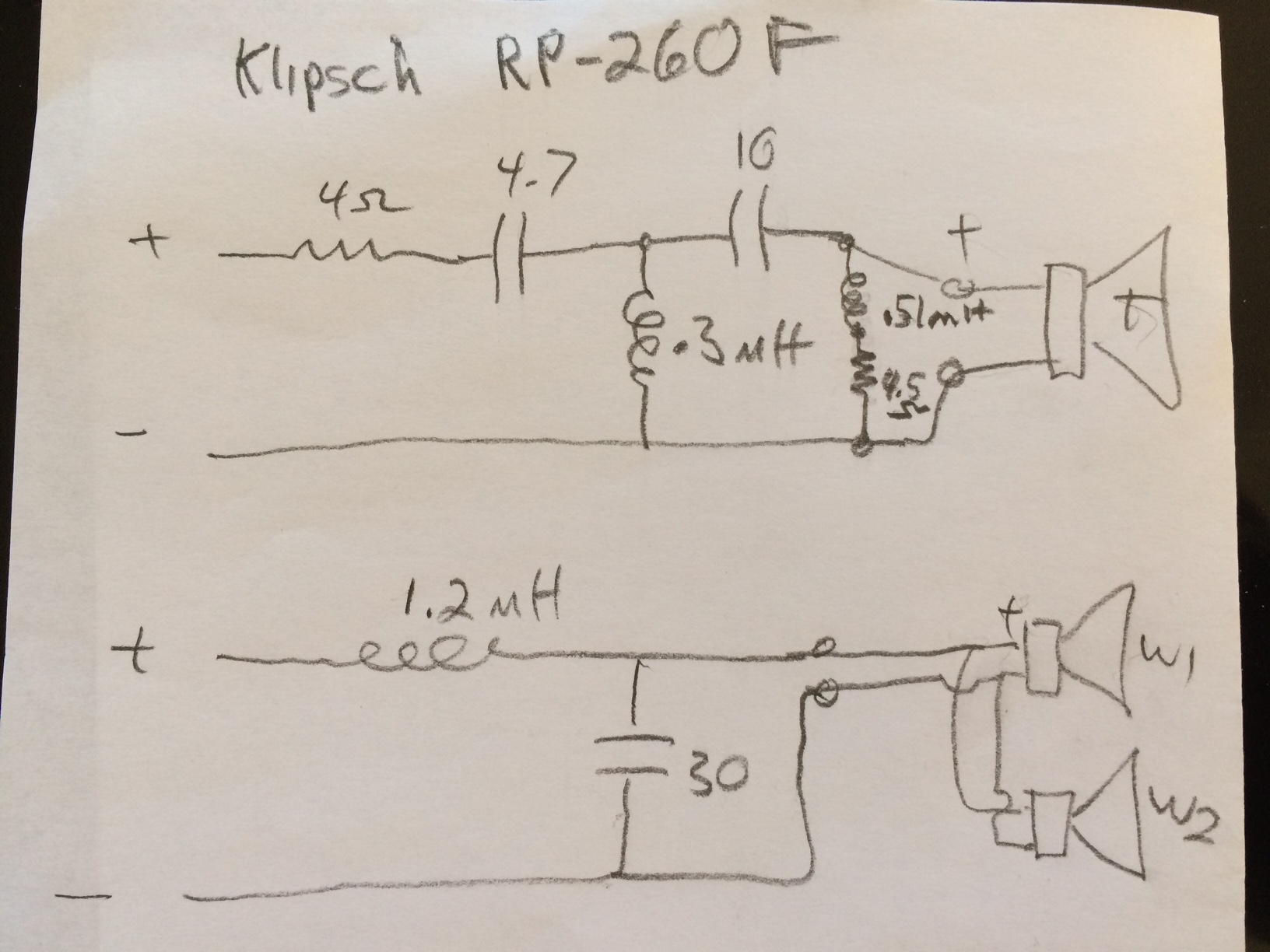
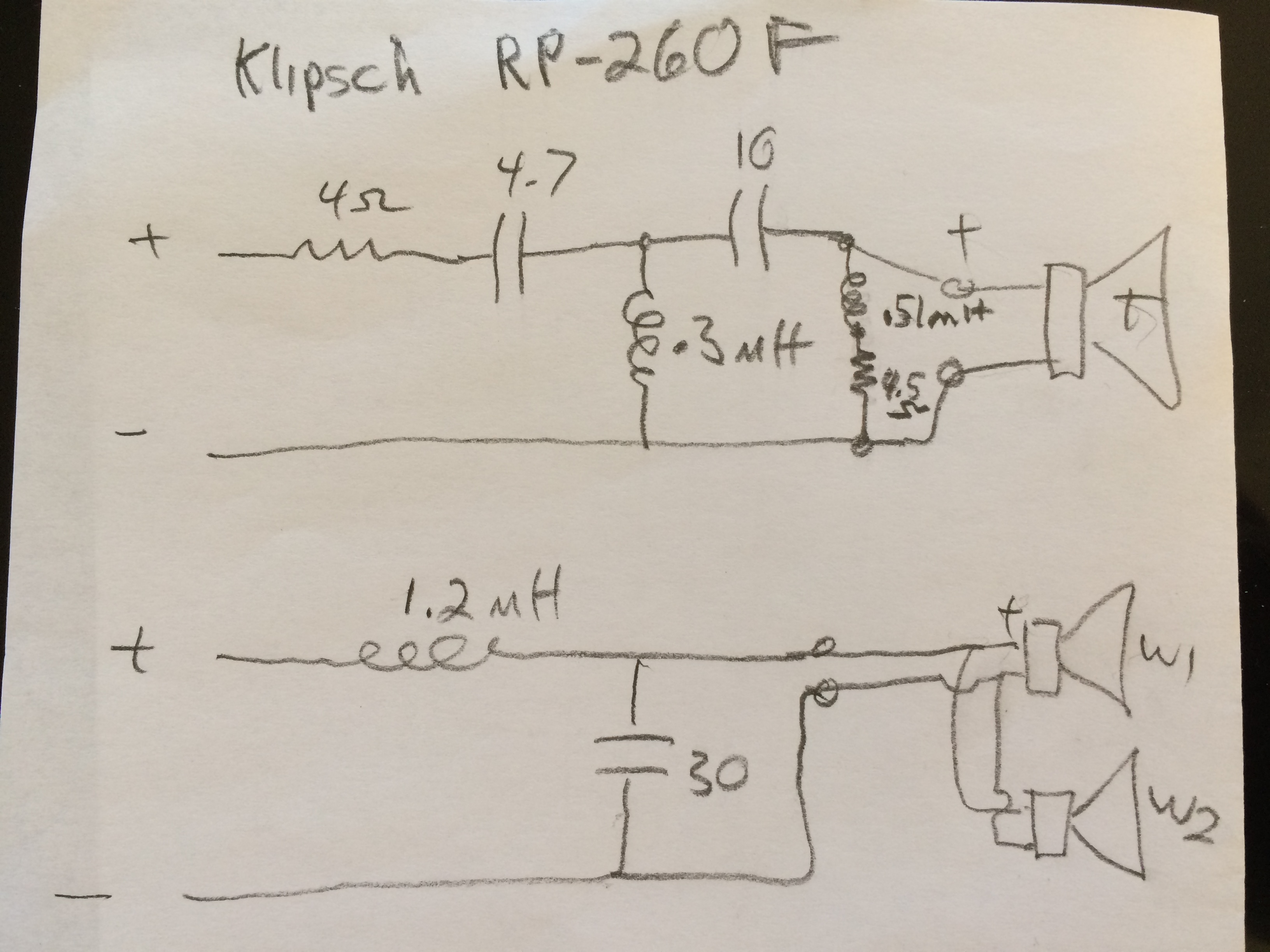
Can anyone tell me what the 0.51mH, 4.5Ohm LR network across the tweeter in the RP-260F crossover above is doing? Is this actually a 4th order xo or is something else going on here? This is my drawing from another thread. I extracted it from my speakers this morning. Thanks, Rich
-
Hey, do you guys know about the "Tissue Paper Mod"? I thought it was a joke, but it really works. Just hanging one single Kleenex tissue across the entire horn with a piece of tape and Bam! instant harshness filter. The only problem is, well, it looks like a piece of tissue hanging in front of my tweeter I want to see my beautiful horn. But seriously, try it if you haven't just for fun. It is no joke. From what I've read the method of attenuation is not absorption by the fibers but reflection back to the driver and cancellation. The basis for this assertion was that when the same tissue was placed over the microphone conducting the tests it had absolutely no effect and appeared acoustically transparent.
-
I don't know. I didn't measure the DC resistance. I should have. Next time I open them up I will. Btw, is it normal that the equivalent series resistance of the horns decreases with increasing frequency (16RSE at 1KHz and 8RSE at 10KHz)? I would have guessed being inductive/resistive they would increase. I wonder if there are some L or C components mounted on the horn driver itself that I can't see from the back port.
-
Thanks. It is good to know there is a place for collecting crossover schematics. I should go find this thread. Maybe they can tell me what the LR network across the horn is doing.
-
I tried the analog Loki 4 band as mentioned above, and the 31 band digital version in the ios app called SpotEQ. I only played with them for about an hour but they both seem to work well. The spotEQ app is really interesting. You can pretty much just drag your finger around the screen and put gain/cut anywhere in the spectrum. When you release your finger there is a sample point there and the EQ fills in the rest with a smooth curve. If you use Spotify it's worth a try. It allows for full Spotify access through the spotEQ app, but you give up the regular spotify GUI.
-
Mr Clean, I just talked to my son and I'm going to borrow his Loki again and give it another try. I like how it is all analog circuitry and very high quality for a great price too. I just got the specs for where it's filters are placed from someone who did some measurements on it. Thanks for reminding me of this little device!
-
Here is a pic of the crossover. Nicely made! Even the LP cap is film type. Serious wireing too. I'm impressed. Note: the skinny little black wires are for the L pad I just installed. They are temporary so I can run them out the rear port for experimentation.
-
Here is the crossover schematic. See what I mean by almost 4th order on the tweeter? What's up with the inductor in series with the resistor acress the horn? Can't be zobel unless horns are capacitive drivers, which I doubt. Anyway, I couldn't find this schematic anywhere online so hopefully this will be usefull to others as well.
-
I am using a simple EL84 PP tube amp. It is Class AB and is running in pentode mode currently. There are no tone controls. The preamp and PI sections are just a couple 6EU7 tubes and negative feedback is set to keep things as flat as possible. I am getting 15 watts RMS per channel on the 8 ohm taps of the output transformers. It sounds amazing with the RP-260's, it's just that the room is a little bright. More carpet might help. Also, every once in a while I get a song that is not so well recorded and come across harsh. These speakers are very revealing. Truly and amazing listening experience!
-
Interesting you should mention this. I just measured the horns and I get 16 ohms at 1KHz and 8 ohms at 10KHz. There are no other frequency options in between on my LCR meter. The pads I have are 8 Ohm.
-
Thank you! In the "old days" when I was a teenager, we all used cheap graphic EQ's, but along the years since then the consensus I was hearing from more sophisticated audiophiles was that tone controls were bad, but to really screw things up required an equalizer. I guess I've kind of subscribed to the thinking that the less tone control in the signal path the better, but maybe I should re-evaluate this. Are modern equalizers much better now? Are the still analog or do they convert to digital for the processing and then back to analog for output? I am currently using a home made tube amplifier and plugging in my iphone directly. Signal source is Spotify on highest bitrate. The amp is a customized EL84 push-pull similar to a Dynaco ST-35. There are presently no tone controls. I did experiment with treble and bass controls and a single tube preamp in this box but they seemed to make the sound better in some places but worse in others so I took them out. It did sound pretty good with the Loki though as mentioned above. The only digital EQ I have access to at present is the iPhone app called SpotEQ. It is a 31 band graphic EQ that is designed to work with Spotify. It seems to work great but is not easy to adjust on the little iPhone screen. I was wondering if digital filtering was a good thing. Is throwing math at the signal better than analog circuits (pots, caps, and resistors, etc)? Again, it would be so great if I could find a parametric version. The freq I want to attenuate most seems to be close to 3KHz according to this app. I'm not sure how accurate all these iPhone apps are, but it is a lot of fun to use the white noise generator and spectrum analyzer to listen to the room. No idea how well they've compensated for the mic, but at least it's fun to play with. Whoa! I see three more posts have come in.
-
Wow! Truly amazing. Thanks for this diagram. This brings up another question I have but didn't want to cram into my first post. Maybe I should start another thread? The question is regarding the Zobel network in this schematic. I have been reading so much about them. I understand how they cancel the imaginary component of the complex impedance of the speaker so the pair looks purely resistive, but I'm not sure if I should add one to my tweeter or not. How important are these? Since Klipsch has been working on refining the horn tweeter for 70 years I would think they must have tried this and would have included it in my current speaker for the cost of one resistor and a capacitor if it made a difference, right? I'm going to take a closer look at my crossovers soon. I seem to recall the HP filter was 4th order, which surprised me since I'v never seen a 4th order filter used, but maybe the last leg was a Zobel? I'll post back with the circuit after I inspect it.
-
Great. I am going to install the L-pads right now and will post back with my results. Though the two fixed-resistor solution is probably more pure, I do like the option of adjusting the level anytime I like. I suppose if I find I am keeping the L-pads at one particular setting all the time I could take them out and measure the two resistances and swap in fixed resistors of the same values.
-
Wow! So many replies! Thank you all so much. I will address a few here and yours is first. Believe it or not, I have tried the Loki 4 band EQ. My son owns one that he uses for his headphone setup. It is a really nice unit, but I don't like being limited to just 4 center frequencies. I have been looking for a parametric version but can't find one. Even a single band full PEQ would be wonderful, but I only seem to find them in guitar stomp boxes. It would be great to have one in a small box like the Loki.
-
Greetings fellow Klipsch owners. I would like to experiment with controlling the output level of the tweeter in my RP-260F speakers. Can this be accomplished by inserting a simple 8-Ohm L-Pad between the crossover and the tweeter? I've seen some fancy level adjustment circuits in other threads involving adjustable tap transformers and I was wondering why a purely resistive approach like an L-Pad wouldn't work as well. Thanks for any info, Rich