


JohnW
-
Posts
327 -
Joined
-
Last visited
Content Type
Forums
Events
Gallery
Posts posted by JohnW
-
-
12 minutes ago, captainbeefheart said:
I agree.
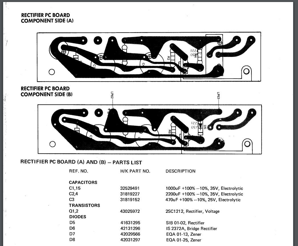
Start with C1 though C9. That's the power supply caps on all three rectifier boards (A,B,C).
Will do, eventually.
In the meantime, I have some raw birch La Scalas to stain and recap, maybe even build some AAs.
I'll do a thread about the recap when I get it.-
 2
2
-
-
If only I had corners.
-
40 minutes ago, babadono said:
Good point. @captainbeefheart @JohnW do you know how old the unit is? If it is +20 years I would go ahead and replace the electrolytic capacitors especially in the power supply section i.e. the rectifier boards. And get rid of that glue stuff as best you can. If you really insist on mechanically attaching use a little dab of RTV (silicone).
Just my $0.02
I believe these were only made 1976-77.
-
33 minutes ago, captainbeefheart said:
Awesome job!!
Okay so we know during normal operation you want to read around 700mV across R9, good to know.
You could have fixed a bad connection. I would go ahead and order the big gray capacitors on the rectifier boards and keep them on hand anyway, probably all of $20 including shipping.
R9 is saving other damage from happening, for instance if a capacitor is leaking not enough current to pop the fuse it can still build heat internally and that's where you will see capacitors bulge out or explode. Instead the resistor is designed with such a low wattage rating that it will burn up with a fault telling you something is wrong.
Happy endings are always the best.
Right after that video I posted, voltage stabilized at .6 to .7--right where it should be.
So I wrapped a piece of electrical tape around the resistor (original was insulated) and soldered it in.
Still a bit of ozone smell coming out of the unit, but that may just be all the dust that's been knocked loose on it's journey from Arizona to here (But I'll keep it in the garage, with a fire extinguisher nearby, until I feel certain about it.
There'a s $99 complete recap kit available on Ebay..but if you think all I need to do is replace the caps on the rectifier boards, that sounds like a lot less to screw up.
This thing sounds tremendous! Previously I was using a sub with my RB5s here in the garage, but this really doesn't need it! Thanks again!
-
2
-
-
Dumb luck, man. Lol. Story of my life:
-
-
6 minutes ago, captainbeefheart said:
I zoomed in on your meter and see what the problem is. You have your meter set to DC volts and you want to be reading AC volts since it's before the rectifier. Sorry I didn't make this clear before.
Dude, you are unbelievably patient. Thanks again.
-
6 minutes ago, captainbeefheart said:
You are absolute certain those are 8.2 ohm resistors and not something like .82 ohms? Can you test the meter and test leads with a battery or something to make sure the meter and test leads are working. Something is clearly way off in reading across the resistor. There is a lot of current passing through it which if it is actually 8.2 ohms then we should be seeing quite a bit of voltage across the resistor.
Something to try to see if the issue is the rectifier board or the load side of the regulator is remove LP53 wire and place a current limiting resistor in series, 100 ohms should do and see if that slows down R9 being smoked. If it does then we know the problem is not on the rectifier board.
Just tested voltage on a motorcycle battery. 12.45v.

-
1
-
-
-
Check out this item on OfferUp. https://offerup.co/ViBFqhzmEnb
-
1
-
-
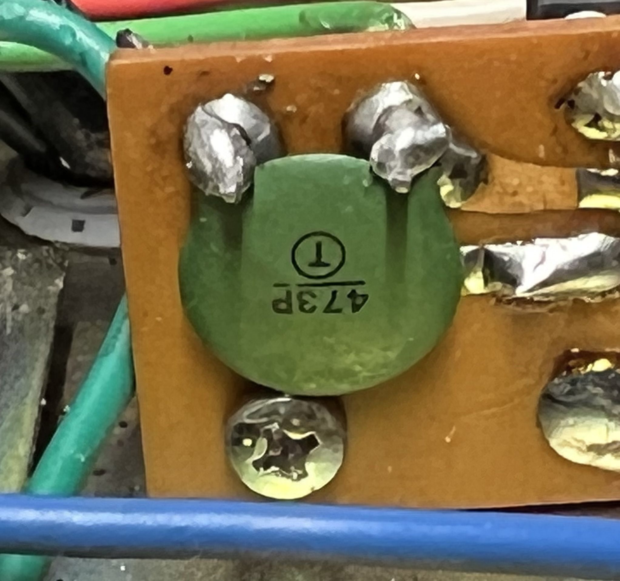
24 minutes ago, babadono said:
I think that green disc capacitor is an oops we gotta add this. it should be 47 thousand pico farads, hence the marking 473P. Any way can you unsolder the B3+ output wires and determine if the rectifier board itself is blowing the fuse or something further down the line.
This appears to be the next step. Though I'm not sure which wires to remove.
-
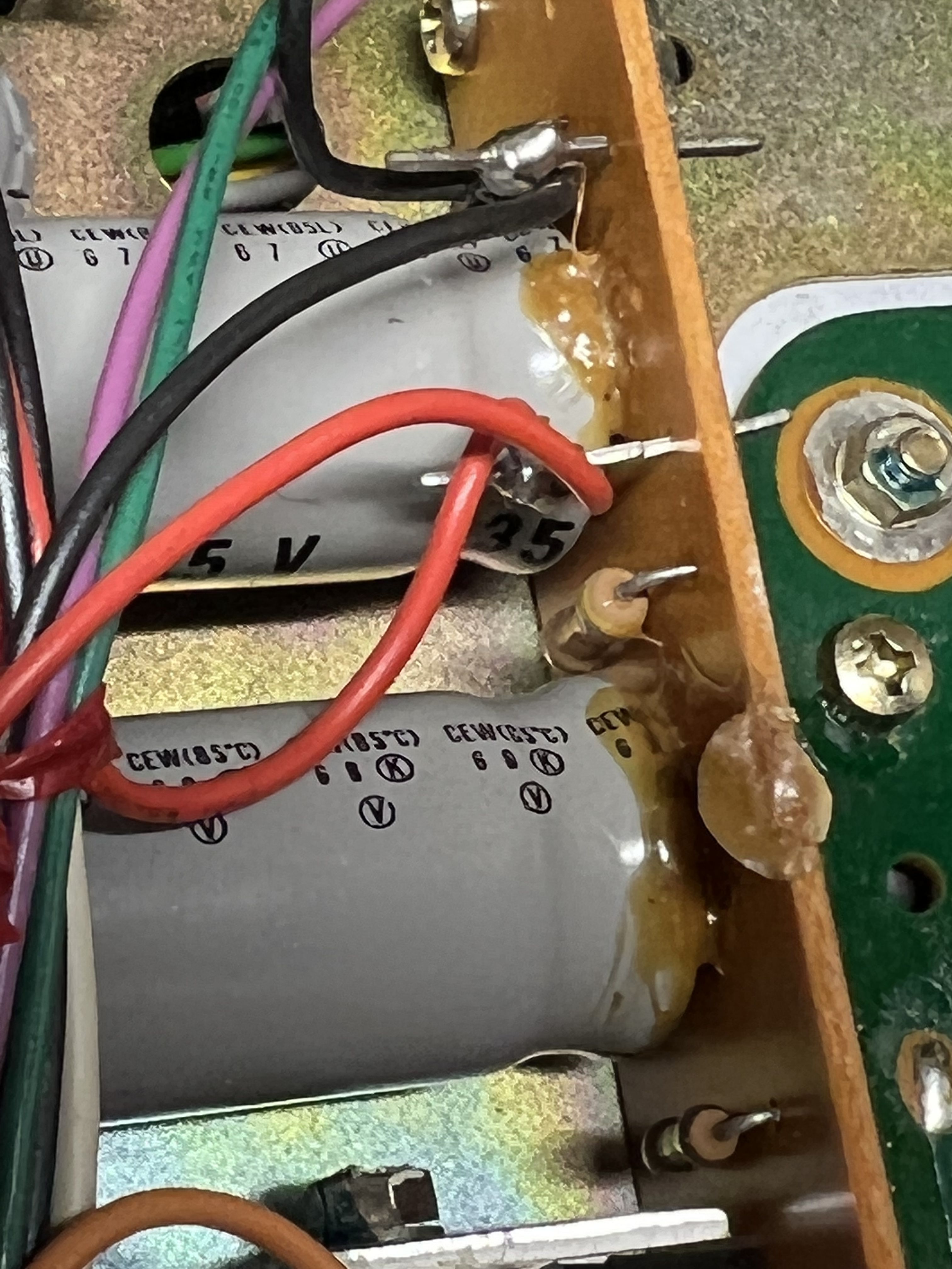
This is just glue, right?
-
Never mind, it has continuity with the next solder point on the board.
can’t seem to find a single short on Rectifier A.
-
I’ve ordered a used rectifier A board from EBay…only $30. Can’t hurt.
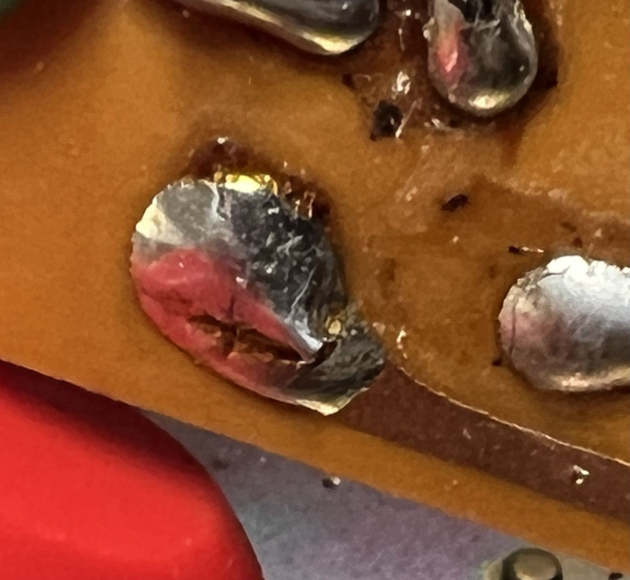
This solder looked cracked? Going to try to add a bit.
-
1
-
-
48 minutes ago, JohnW said:
Here’s a new discovery…
every diode, resistor, capacitor on Rectifier A board shows at least some conductance…
Except this little guy, which is the next link in line after the R9 resistor.
Ok forgive my ignorance, but what is this? The C5 capacitor (which seems to be conveniently missing from the HK parts list)?

No, it's in the parts list. And I just pulled it out. It's fine. Tested perfectly at 47uF.
-
And while the capacitor seems to be missing from the Rectifier Board A list, the list does include two zener diodes, which I can't seem to find anywhere on the board.
But I'm highly inexperienced, so maybe I just don't know what they look like.
-
On 2/12/2022 at 4:23 PM, Marvel said:
I'll go out on a limb here... are the lamps in the 430 in sockets, i.e., like fuse holders? I blew up a receiver once... put a fuse in a lamp holder. It took out to much for me to continue when the power came on.
Thankfully, no. These are for sure fuse holders. Labeled as such, and on the bottom of the unit.
-
 1
1
-
-
Here’s a new discovery…
every diode, resistor, capacitor on Rectifier A board shows at least some conductance…
Except this little guy, which is the next link in line after the R9 resistor.
Ok forgive my ignorance, but what is this? The C5 capacitor (which seems to be conveniently missing from the HK parts list)?
-
And I wouldn’t BEGIN to know how to check B3.
-
So if I read this right, there wasn't too much current going through the resistor...yet the resistor still cooked?
So...too much current? -
Thought this might be easier than explaining:
-
Holy shit, I actually followed that. Resistor in and voltage will be measured in the morning.
Note: Original resistor was insulated.
-
The fuse did not blow. I measured it without the resistor in the circuit. You’re saying I should put the resistor in before I measure?
-
Ok, multimeter across R9 set for 2 volts reads fluctuations from -.02v to +.02v
should it be fluctuating, or hold steady?
Harman/Kardon 430 Twin Recap List
in Technical/Restorations
Posted
Just resurrected mine (link attached). Sounds SHOCKINGLY good. Really curious how yours sounds, because if I can improve on this, I'll be...well, I don't know. I'm already amazed.