captainbeefheart
-
Posts
1422 -
Joined
-
Last visited
4 Followers


captainbeefheart's Achievements
Forum Veteran (4/9)
831
Reputation
-
Cheap Forum Amp by Captainbeefheart
captainbeefheart replied to MEH Synergy's topic in Talkin' Tubes
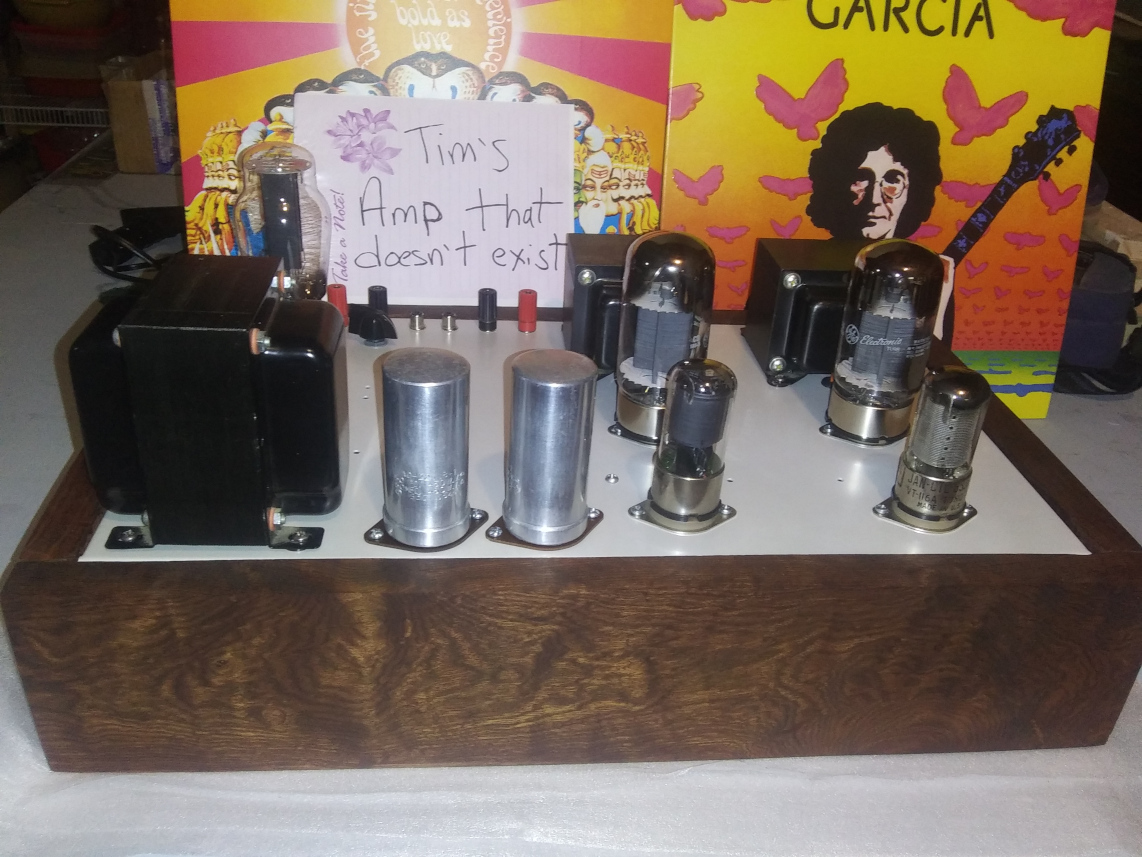
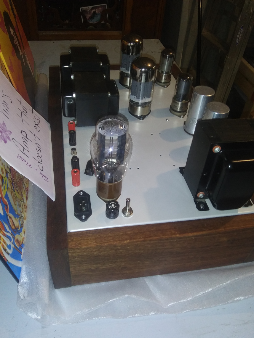
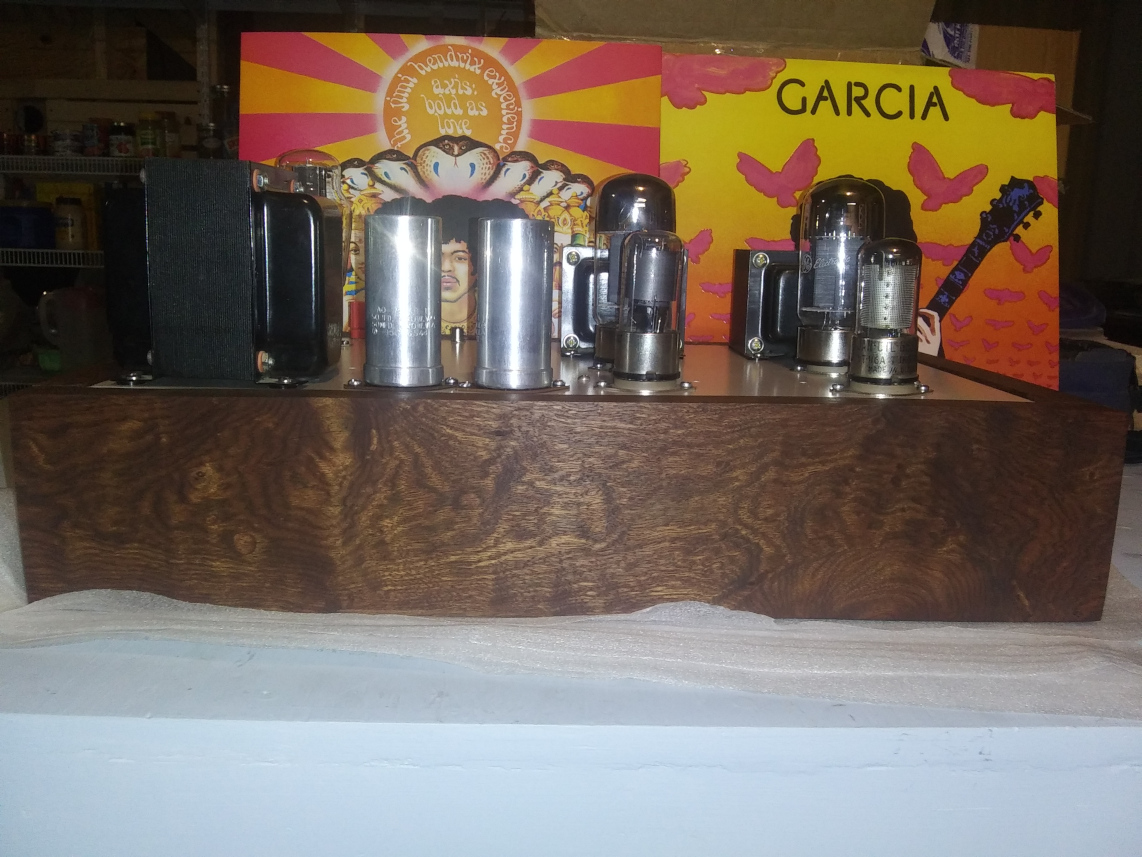
Shakey, stop lying to evoke sympathy from members on here. Be a MAN and tell the truth!!!! You called the police and sent me a text saying that you DO NOT want the amp anymore. I asked you one last time to be certain that you don't want it and here is your EXACT quote; "No, I'm done. I don't want the damn thing anymore. Just sell it, if it even exists, and send me my money." So now I am trying to sell it to send you the money and I'm the bad guy? Talk about a drama queen for attention. Stop the act and stop lying to people about the whole situation acting like you have no idea about me selling it when it was YOUR IDEA. -
Cheap Forum Amp by Captainbeefheart
captainbeefheart replied to MEH Synergy's topic in Talkin' Tubes
Since Shakey couldn't stop harassing me and his "gang" from here got me booted for lies on another forum I told him I wasn't going to send the amp off with the NOS GE 6550's and that I was waiting for current production KT88's to arrive before I ship the amp off. I was also having Linda finalize the owners manual with bias instructions with annotated images etc.... Instead he called the police on me and told me to sell the amp and send him the money so that's where we are at. The amp exists contrary to lies being spewed by people that cannot relax about getting an incredible deal on an amplifier so they don't get it anymore. Or should I say, they don't deserve it anymore. Others that say you cannot get a great amplifier for the price Shakey paid, you can, you just have to be patient and let the builder do what they do best. Especially since it's not their full time job and want to only send out excellence as promised. I'm done with this place but I won't have people spewing lies about this being fraud or a scam. That's completely made up by someone that didn't get what they wanted fast enough. At least Chris will get a killer amp and can laugh at all of you when he gets his. Chris is cool, he knows not to bug me and when I finish I will send it off and he will have at least a $5,000 amplifier for 20% of the price. Being patient has it's virtues.
-
Crossover A Klipschorn cap replacement help
captainbeefheart replied to Aoran994's topic in Technical/Restorations
I know there is some long winded technical posts in here, especially by me but the main takeaway points are; JEM caps are the easiest way for anyone to replace caps and get the intended sonic signature. Sadly the OP is in Italy and exporting them there is not cost effective so we want to try and get him something that will fit form and function to retain the intended sound of the speakers. The simplest way to achieve this is to use the same type of capacitor, in this case Mylar/Polyester which has specific properties that we want to retain the same electrical results. One major factor is not just that DF is high with Mylar/Polyester but it varies quite drastically depending on temperature. I.e. Capacitor quality changes with temperature. Paper capacitors have very similar properties which is another great option when choosing replacement parts. Other types of film caps like Teflon or Polypropylene are too high quality, the DF is far too low to keep the same sound and these caps are very consistent in quality vs temperature. I.e. at temperature extremes DF stays low. With Polyester or Paper at temp extremes DF will increase quite drastically. Simply put, brand has nothing to do with anything, choose replacements based on type of Dielectric. If in doubt find datasheet of said capacitor and look for DF in the datasheet given as a %. You want a capacitor that has a DF ~ .5% -
Sunday morning Type E crossover build
captainbeefheart replied to Wardsweb's topic in Technical/Restorations
A proper crimp tool will help make an optimal crimp for sure. Contacts that show the following conditions shall be prohibited: a. Cracks in the plating or base metal. b. Tarnishing or discoloration of the plating. c. Plating removal or flaking. d. Out-of-roundness of the wire well entrance. e. Exposed base metal I doubt a capacitor with thin tinned copper leads would be put into this style crimp connector in a deep space satellite. The crimp will most likely lead to exposed base metal in the cap leads with possible damage/cracks into the plating or base metal. Both have pros/cons, I wouldn't put one over the other generally. Nasa uses both solder and crimp in the last technical standards release I have; NASA-STD 8739.4A released to public in 2016 I completely agree. I only mentioned it because I have seen failures from people using these exact type of crimp connectors with electrical components thin leads in various Industrial control panels. They most likely used standard electrician crimp tools and probably didn't understand how to make a quality crimp connection like you. As you point out it's a simple fix regardless. Now that I know you have a solid background and know what you are doing I wouldn't have even posted. I figured I could possibly help someone that may not know anything about quality connections but you are a professional so disregard my nonsense. -
Crossover A Klipschorn cap replacement help
captainbeefheart replied to Aoran994's topic in Technical/Restorations
Yes indeed, that's why I said if they are sealed correctly they can last a long time. Unfortunately in many vintage receivers they are not hermetically sealed. I am a big fan of high quality PIO capacitors in certain applications. Lots of industrial equipment still use paper or hybrid paper/film. I was curious to try these in my Heresy Type E's but the price isn't great and I can get Russian military PIO much cheaper from Bulgaria. 2uF paper 1kV (2kV peak), good for high peak current/voltage and pulse applications so they should be excellent for audio. https://www.mouser.com/ProductDetail/Cornell-Dubilier-CDE/SCRN234R-F?qs=9I6i58cghus89mz%2F6eojrA%3D%3D -
Crossover A Klipschorn cap replacement help
captainbeefheart replied to Aoran994's topic in Technical/Restorations
I agree with films rarely fail. The metallized types that are self healing repair themselves but the "clearing" action of these failed spots cause a decrease in capacitance value since essentially that small section of dielectric film and plates have been vaporized and surface area has been reduced. Along with Aluminum Electrolytic caps paper in oil types are prone to fail from age due to the paper absorbing moisture. If the PIO construction has an excellent seal then they can last quite a long time but most of the regular molded paper types are junk now. -
Crossover A Klipschorn cap replacement help
captainbeefheart replied to Aoran994's topic in Technical/Restorations
That's what gets me, they inflate the claims so much that you almost feel you have to be doing this since it makes such a "huge" difference. I have seen the improvement first hand with caps that have terrible DA characteristics but that's pushing the capacitor into an area of operation to see the hysteresis. I.e. lots of signal across the capacitor. This would mean that signals beyond and below the corner frequency would be where the distortion arises. In a balance/crossover network application, the signals below the corner frequency are the ones we are filtering out and away from passing through the driver. So even if this is where we are starting to see some distortion from the capacitor it's kinda moot since these are not really frequencies of interest. The frequencies we want to pass through the driver aren't going to see the capacitor as a high impedance, and so there isn't going to be an appreciable amount of signal across it and therefore no distortion. We heard it from the horses mouth that the selection for capacitors in these networks were made to retain the desired transfer function and that was the primary criteria. I did not hear him mention low distortion as a major design parameter when selecting replacement capacitors for legacy products. As for what caps to use in the JBL 250, I'll be honest I don't have much experience with these speakers other than hearing them a handful of times. That, and I kinda chuckle at the schematic with all their bypass capacitors. For example on the woofer section they use smaller caps to bypass the larger ones but then tie all the grounds together and run them through a resistor back to the source. Why would you give the high frequencies a low impedance path around the larger caps only to impede them with a resistor? I figure the resistor is there to dampen some resonance but if they really wanted to give the high frequencies a low impedance path back to the source why also run them through the resistor? I can't see any reason to having these bypass caps for the mid-frequency or even high frequency drivers, but possibly for the ultra high frequency driver. Personally I wouldn't touch any of the capacitors unless they needed to be replaced and then I would simply stick with the same type of capacitor. It's a more complex network compared to most of our heritage Klipsch networks and so I really couldn't give an excellent analysis without sitting down and working through the entire design with drivers included. -
Crossover A Klipschorn cap replacement help
captainbeefheart replied to Aoran994's topic in Technical/Restorations
People may not be getting physically hurt, but in the audiophile world I do think there should be a little better consumer protection to not get financially hurt. Of course nobody is holding a gun to anyone's head to purchase anything but the sales literature I feel on many things is false advertising. Take a pharmaceutical company selling a pill for say flu treatment but it's only a sugar pill. There would be reviews of people claiming the pills worked and made them feel better from placebo effect. Then whatever agency finds out that the pills are a scam and they are just sugar pills. The company could claim nobody was hurt and people actually benefited from the placebo effect. Morally these companies are not supposed to conduct themselves in this way and there should be consequences. There is a certain amount of trust. Taking advantage of human behavior is wrong no matter what the industry in my opinion. If you spent your life educating yourself in a field and you use your knowledge to dupe people for profit then that's wrong. People read the sales literature and they make it very convincing due to the technical language and regular people that aren't engineers aren't going to know what they are talking about but it sure sounds legit. I'm not saying the theory isn't correct and with capacitors that have very high dielectric absorption there could be a benefit but I'm sorry, for someone to claim that it makes a "huge difference" with a capacitor that has a DA of .01% then I say that's rubbish. When we are talking about changing something that's -140db or lower it's just not going to make a lick of audible difference due to the transducers always being the weak link in the chain. We are all limited by our speakers, transducers are the weak link in the chain because driver distortion is always going to be far higher than the distortion in the electronics. Tube amps can sound excellent and they are known to have higher distortion than their SS counterparts. Tube amp people will argue distortion isn't everything in regard to sound quality in these situations so then why waste time with trying to improve a capacitor that is showing no distortion down to -140db? Especially when their SET amplifier is producing 5% THD at 2 watts do they really believe they are going to hear a change of .00001%? Essentially you are saying you can hear the difference between 5% THD and 5.00001% THD. See how silly that is? Since they have given us the mechanism, and it's well understood. The DA can cause distortions of the waveform around the zero crossing so then it should be easily measurable. The problem is that with a cap that has a DA of .01% most of us can't measure distortion down that far, let alone hear it. Especially when the transducer is giving us 1% THD and that's being fair. We call that a problem we don't need to worry about, there are bigger fish to fry in the signal chain. https://www.syclotron.com/capacitor-obsessions-the-zombie-awakes/ -
Crossover A Klipschorn cap replacement help
captainbeefheart replied to Aoran994's topic in Technical/Restorations
LOL I just read all that and it's exactly as I presumed, it's to remove hysteresis caused from the dielectric absorption. As most techs have noticed after you short an aluminum electrolytic capacitor to discharge it and then remove the short voltage builds back up. Just like dissipation factor, dielectric absorption is given in a %. The lower the % obviously the less DA the dielectric exhibits. With a film capacitor the DA is around .02%, actually polystyrene caps are a magnitude lower at .002% Aluminum Electrolytic caps will have a DA of 10% which is why you should bias them. With a film cap the DA is just so small it's not going to be audible but in theory it is present and measurable. JBL used this trick to allow using cheap Aluminum electrolytic caps in their networks and the bias lowers the hysteresis distortion down to acceptable levels. For 20v the DA would be; 20 * .0002 = 4mV film 20 * .1 = 2v aluminum electrolytic -
Crossover A Klipschorn cap replacement help
captainbeefheart replied to Aoran994's topic in Technical/Restorations
I found these. I haven't read through it yet but I will and report back. -
Let's see if the speakers and cables work. Disconnect the speakers from the amp at the back of the amp so the cables are still connected to the speakers. Then take a battery, doesn't really matter what kind of battery, I'd try an AA battery first and then maybe try a 9v if you don't hear anything with the AA. Each speaker has two wires, you are testing one speaker at at time with two wires. Hold one of the speaker wires to one side of the battery, doesn't matter + or -. Then tap the other speaker wire to the other side of the battery. You should hear thump noise each time you tap the wire to the battery. Don't hold both wires to the battery for a long time, you are just making quick connections on/off. Repeat with the other speaker. If you hear noise from the speakers then it's your receiver that's the problem. Essentially you are making a pulsed square wave signal to the speaker with a battery. Depending on the polarity of how you connect the battery the speaker will either push outward or pull inward each time you tap the battery with the wire. This is also a very useful trick to test phase of a speaker if you are unsure. Placing the + of the battery to the + of the speaker should push the cone outward.
-
Crossover A Klipschorn cap replacement help
captainbeefheart replied to Aoran994's topic in Technical/Restorations
I have never measured a single improvement from DC biasing bipolar film or paper types. The times I have asked people how this improves a bipolar cap I wasn't completely satisfied with their answer which was along the lines of "removing crossover distortion at the zero crossing". With a polarized capacitor the anode forms the dielectric oxide layer when charged so I can see how keeping the anode oxide layer formed all the time via a DC bias will help. If you have ever discharged an electrolytic and removed the short/load you will see a charge form up from the dielectric absorption. Also in testing you can see it reduces hysteresis so it's definitely helping matters. One thing is doesn't change the non-linearity but in a coupling capacitor situation distortion is no different than a film anyway so that's moot. Coupling stages usually block DC so the bias is already there. Many SS amps will have tons of lytic caps in the signal path and you don't hear people complain about the sound, it's way over exaggerated that polarized lytics are going to poison the signal. I can only say I have seen a DC bias improve polarized electrolytics. Really I think the issue is using the two polarized caps back to back to create a bipolar cap works but there must be a mechanism with this arrangement that just doesn't perform well enough for serious audio uses. I feel there is no point for me to spend a lot of time on investigating what's going on at a deep level here since I wouldn't ever use polarized back to back anyway in a crossover and if I had to use a very large value of capacitance because of a low impedance load in an amp there is often a DC element there to bias the polarized coupling capacitor anyway. Until I see a good explanation and some actual data showing DC bias helps bipolar film caps I'm not on board with that idea. -
Crossover A Klipschorn cap replacement help
captainbeefheart replied to Aoran994's topic in Technical/Restorations
@Travis In Austin attenuation, or insertion loss is different than distortion. With a loss, or attenuation - the shape of the waveform at the output is identical to it's input, only smaller. Distortion means that the waveform has changed it's shape, the output waveform is not the same original waveform that was at the input. -
Crossover A Klipschorn cap replacement help
captainbeefheart replied to Aoran994's topic in Technical/Restorations
Yes. That's exactly what DF is, the higher the DF % the more lossy the capacitor will be. That larger drop in voltage at the output across the ESR. -
Crossover A Klipschorn cap replacement help
captainbeefheart replied to Aoran994's topic in Technical/Restorations
I should have explained what you are seeing, sorry. Linear, line - basically the straighter the line is the more linear the cap is. With the ceramic you can see how as the line isn't straight, it has a curve to it. With the Tantalum and Electrolytic the hysteresis is so bad it hides the non-linearity. So nope Tantalum isn't the best, it would have high distortion. But who knows, people love amps that produce over 1% THD below 1 watt so someone might like the high distortion effect.