RealMarkDeneen
-
Posts
457 -
Joined
-
Last visited
Content Type
Forums
Events
Gallery
Everything posted by RealMarkDeneen
-
Yes. An iPhone 14 Max with 1TB is $1599.00 I'm sure someone is buying them. Uh, not me!
-
Not saying they are dead, but if they are they had a good run of about 53 years. Considering how specialized their market place is, that's PDG. In 1970, pretty much all young men were interested in audio gear. I'm from that era and I got my first "real stereo system" in 1969 - and so did all of my friends. I'm just spewing, but I would guess that today, a young man with $1500 will spend it on a telephone to carry around in his pocket before he would buy a piece of high end audio gear. "Tiny, plastic, portable, digital, cheap, and offshore" - - all the qualities that ARC amplifiers don't possess! I hope they make it. It is a great company with a great tradition of excellence. In 1974 when Bruce and I designed our first preamp at Paragon, the ARC SP3a was the "gold standard" for most who were in the know. Very intimidating.
-

Maybe You Have A Juicy Question?
RealMarkDeneen replied to RealMarkDeneen's topic in 2-Channel Home Audio
Hi-- For the green winding you set the DVM to AC Volts. Put one lead on each wire. You should get about 18V or something like that - I can't quite recall but something like that. Now then, if you do that by slipping the probes into the white molex connector, you might NOT get a valid read because on some units the spring terminal crimp goes bad and you won't get any volltage reading. If such happens, you have to unplug the green wires, "re-crimp" the spring lug, re-insert them and try again. It is VERY RARE for the green winding to be burnt out, but not too rare for the spring lug to go bad. Now, to check the LM350, just set your DVM to DC Volts, and place the black lead on the ground terminal of the chassis and touch the red lead to the top side shell of the LM350 which sits inside the 2" square black heat sink. This reading MUST BE at least 6.1VDC and can be as high as 6.5. If you get a reading like 5V, or 4.5V, that means the mounting has loosened up. There are four bolts holding it down. You have to retighten the 4 bolts to a "firm setting" but don't go crazy and tighten so much that the PCB flexes!! Be careful. That should bring the voltage back up to the proper range. If you need more email me directly at aroadrunner@protonmail.com. We'll get it figured out! Cheers, Mark -
Maybe You Have A Juicy Question?
RealMarkDeneen replied to RealMarkDeneen's topic in 2-Channel Home Audio
Bravo! Nice to hear of another "recovered" unit! -
Maybe You Have A Juicy Question?
RealMarkDeneen replied to RealMarkDeneen's topic in 2-Channel Home Audio
6H30 Upgrade The Merlin, BBX, and Peach have individually unique changes for 6H30. Because one of the PSU resistors needs to be changed to reduce plate voltage. Although the upgrade only involves a few parts, it can get tricky due to the many versions of each PCB. The plate & cathode resistors change on that tube socket, and at least one PS resistor. But, to be sure it is right, you have to be able to use a DVM to check voltages, and you may need to "adjust" the size of the plate resistor to match the board version you have. Also, yuo may have to VISUALLY trace the plate load resistor trace on the PCB back to the PS to see which LC is feeding it. Before anyone jumps into that, I will need to do some digging regarding the right voltages. I DON'T have a 6H30 unit here. My Peach is 6DJ8. Cheers! Mark -
Maybe You Have A Juicy Question?
RealMarkDeneen replied to RealMarkDeneen's topic in 2-Channel Home Audio
Fantastic. Looks great to me. I see you have some "curl" in your rear label. I peeled those off and then remounted them with Weldwood Contact Cement (the original Weldwood, not the one sold now in California). Also, see my post about adding vent holes to your cabinet. Cheers! Mark -
Maybe You Have A Juicy Question?
RealMarkDeneen replied to RealMarkDeneen's topic in 2-Channel Home Audio
There was only ever ONE transformer used by every JMA preamp. So, yes - no trouble at all. Cheers! Mark -
Maybe You Have A Juicy Question?
RealMarkDeneen replied to RealMarkDeneen's topic in 2-Channel Home Audio
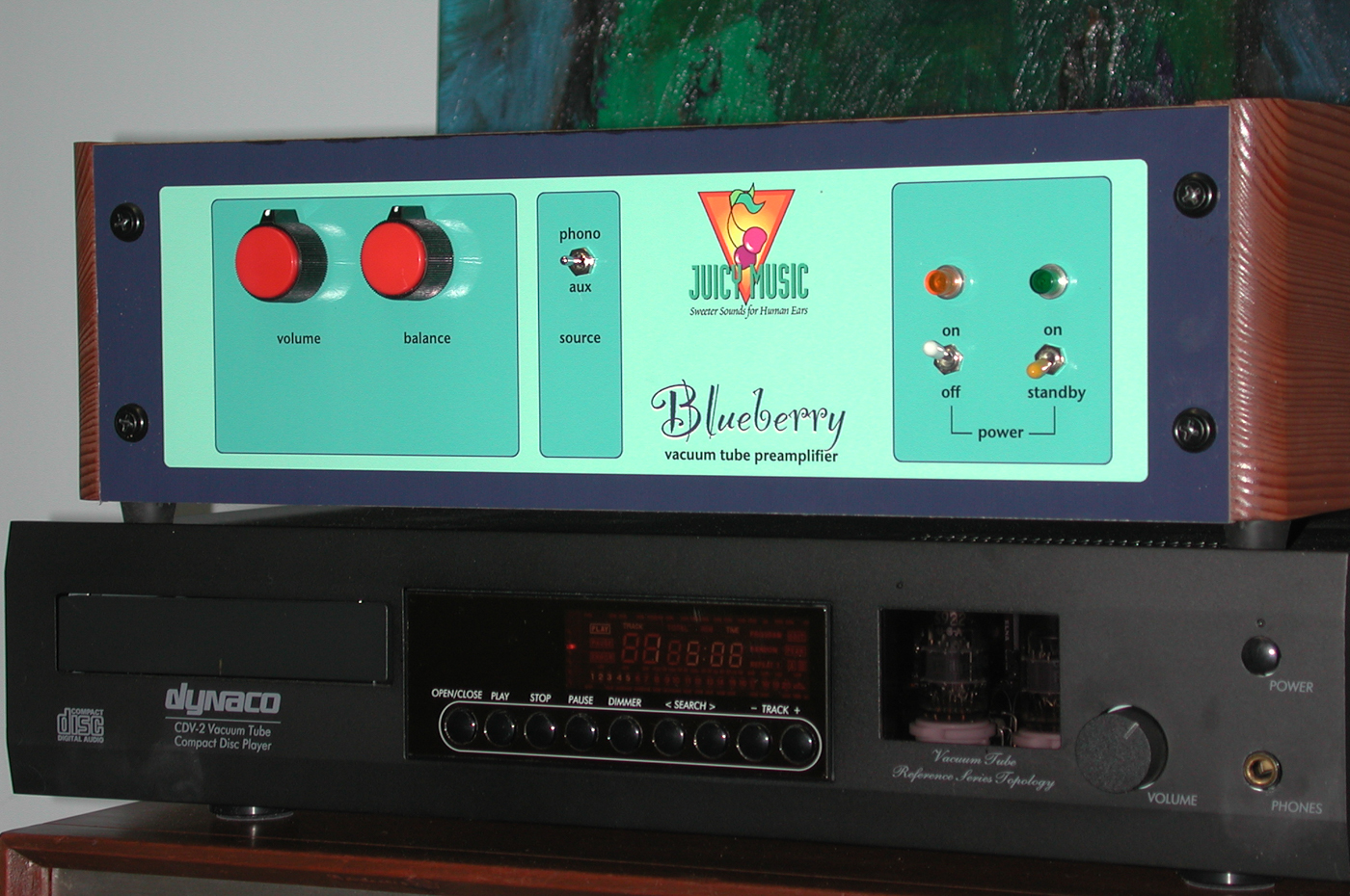
Yeah, those first ones generated a LOVE/HATE reaction. I was very happy with it - even though it was way toned down from my original prototype look. I built this mockup one weekend and most thought it was way too far over the top. I toned it down. But my heart was always in the more wild colorful playful version.
-
Maybe You Have A Juicy Question?
RealMarkDeneen replied to RealMarkDeneen's topic in 2-Channel Home Audio
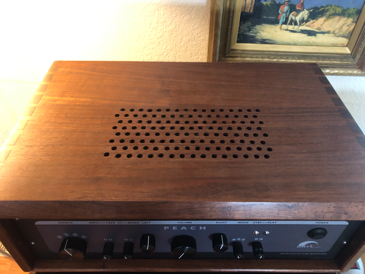
More Heat Relief While we are on the subject of heat. I highly recommend adding a hole pattern to the tops of any wooden box that might have come with your JMA Peach/BBX. Here is what I recently added to my "new Peach". It is simple enough and very effective what I can tell so far. I should put some probes inside and measure, but I haven't yet.
-
Maybe You Have A Juicy Question?
RealMarkDeneen replied to RealMarkDeneen's topic in 2-Channel Home Audio
Well done, John! Thanks for providing that info. I am sure others can use that as a guide. I usually mount the new rectifier on the bottom of the chassis behind the xformer, but your location looks perfectly fine. Cheers, Mark -
Maybe You Have A Juicy Question?
RealMarkDeneen replied to RealMarkDeneen's topic in 2-Channel Home Audio
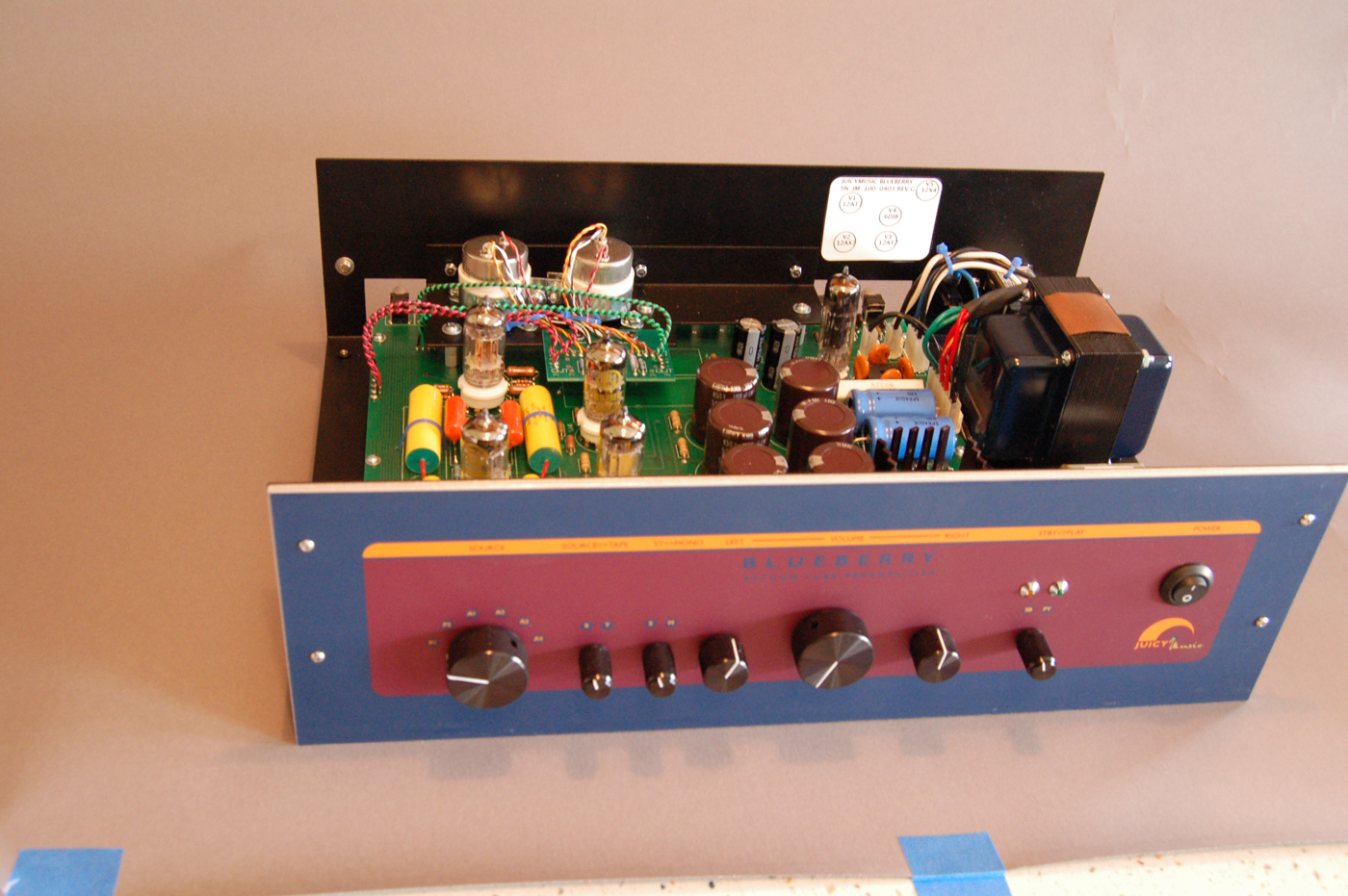
Here is a BBX from the inside. Notice that there is plenty of room above the PCB stiffener shelf (where the Cream sits) so drilling through is no issue even with a Cream unit.
-
Maybe You Have A Juicy Question?
RealMarkDeneen replied to RealMarkDeneen's topic in 2-Channel Home Audio
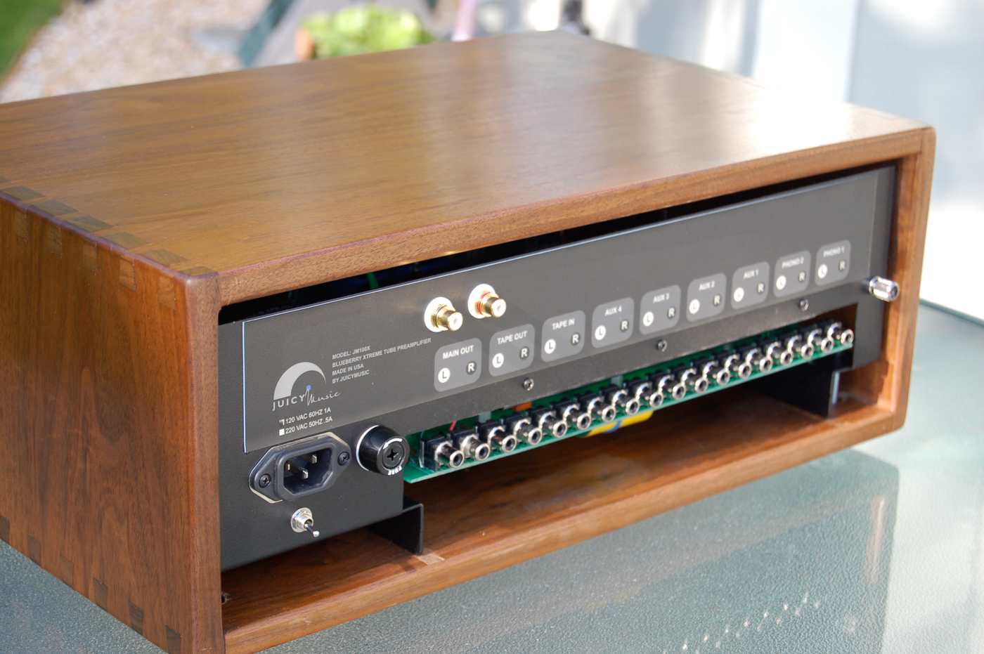
Here's one with a partial set of jacks. It's the only pic I could find. Plenty of room for the jacks. And then the bottom will remain open. NOTE: Before DRILLING into the back cover the PCB with plastic wrap and tape it down all around the edge so that do drilling chips get lodged under a resistor or something like that. As you can see here, I just drilled right through the label and left in place.
-
Maybe You Have A Juicy Question?
RealMarkDeneen replied to RealMarkDeneen's topic in 2-Channel Home Audio
Yes, that's my recommendation. I think they will all fail with time. Especially if it sits on for 8 hours at a time. I have had enough failures to believe they will all fail. Cheers! Mark -
Maybe You Have A Juicy Question?
RealMarkDeneen replied to RealMarkDeneen's topic in 2-Channel Home Audio
REPLACEMENT BRIDGE RECTIFIER DIGIKEY 641-1381-ND About $5. This should be done for all BBX and Peach models. Easy fix. Mark -
Maybe You Have A Juicy Question?
RealMarkDeneen replied to RealMarkDeneen's topic in 2-Channel Home Audio
RCA JACKS I have done at least 3 or 4 units in the past with panel mount jacks. I did NOT need to add an extra plate. There is sufficient room on the rear of the chassis above the opening where the rca jack protrude from the PCB. If you cut the upper part of the vinyl label off, there is just the right amount of space. (If memory serves). I know I never added any plate when I've done this in the past. If you do add a plate you will be eliminating some of the cooling. -
Maybe You Have A Juicy Question?
RealMarkDeneen replied to RealMarkDeneen's topic in 2-Channel Home Audio
Got it. I'll send some details to you in the morning. Mark -
Maybe You Have A Juicy Question?
RealMarkDeneen replied to RealMarkDeneen's topic in 2-Channel Home Audio
Not for dissipation. It's just that the aluminum won't shrink when the insides of the unit get warm. The nylon literally shrunk by about 1//10". NOTE: If you plan to replace the nylon for aluminum, you have to desolder the LM 350 and then resolder it. No biggie. -
Maybe You Have A Juicy Question?
RealMarkDeneen replied to RealMarkDeneen's topic in 2-Channel Home Audio
Fantastic! -
Maybe You Have A Juicy Question?
RealMarkDeneen replied to RealMarkDeneen's topic in 2-Channel Home Audio
I know a lot of this sounds dreadful with all the problems. BUT.......if one can do the mods and repairs (or have them done), they will run for a long time trouble free. There were some design mistakes, but nothing that can't be resolved. -
Maybe You Have A Juicy Question?
RealMarkDeneen replied to RealMarkDeneen's topic in 2-Channel Home Audio
There were really FOUR consistent failures. 1) The above mentioned Bridge Rectifier in either the BBX or Peach 2) The loosening up of the LM350 regulator on BBX and Peach. This is what would happen: The normal heat in the unit would soften the four NYLON standoffs that I used to hold the LM350 and it's 2" x 2" Heatsink to the PCB. They nylon would shrink down, the screws would loosen slightly, and the voltage would drop from 6.3 to 5, then 4 then the unit would stop working. One simple fix was to retighten the four screws. The better fix was to remove the nylon spacers and replace with aluminum and retighten. 3) The remotes in either of the ones that had remotes. The remote failure was simply this: The receptor sat behind a simple hole in the front panel, and it would get tweaked away from lining up with the hole. 4) The RCA jacks on BBX and Peach would get tweaked off the PCB. In many ways, this was the more regretful part of what I did. I wanted to hold the cost of the unit to well under $2 grand. And wiring 20 panel jacks was going to add a lot of labor. I saw these PCB mount jacks and an opportunity to save hours of labor and I designed it so there was no "wire" and used relays and a PC mount selector. It was all VERY LABOR SAVING, but just too fragile for reality. Big mistake. Now, those jacks are unobtainable. The solution is to drill 20 holes in the back panel, mount panale mount jacks, wire them into the PCB holes. Takes an afternoon to do it, but makes the unit bulletproof. I can't recall any repairs on Merins, and maybe a few minor ones on Tercel. Nothing "chronic" on either of those. The second version of Tercel was REALLY ROBUST. I don't think I ever saw one back for repair. pCAT had a few troubles, but not too bad. The welding on the chassis covers was shite. The fabricator did a crap welding job and the covers came apart in shipping. And on maybe two units a 2W resistor in the PSU burnt out. And the big star ground with big copper wires came loose from it's BOLT that kept it tied to the chassis on one unit. The biggest problem was shipping those things. Nearly impossible. Cheers! Mark -
Maybe You Have A Juicy Question?
RealMarkDeneen replied to RealMarkDeneen's topic in 2-Channel Home Audio
Replacing the bridge rectifier on BBX The next more common problem is the heater circuit BRIDGE RECTIFIER, and associated RC filter network. The rectifier is mounted directly on the PCB, and the spec was too low. They overheat and burn out. NOTE: if the bridge is burnt out, it might have taken the two large filter caps with it. Be alert for blown caps. Do this: --Locate the black plastic bridge rectifier – about 1.2” square near rear of PCB. --Draw a diagram for your self noting the orientation and location of the PLUS, MINUS, and two AC pin locations. --Desolder and remove the bad rectifier --Remove all ceramic noise capacitors and throw them out, do not replace them --Obtain at least a 25A 100V replacement bridge preferably with a metal base plate. --Attach 4 color coded 14ga wires about 8” long to each of the 4 bridge lugs --Drill a suitable hole through bottom of the Peach chassis near the PCB location where the old bridge was removed. --Mount the bridge with a sturdy nut and bolt and washer directly to the chassis to act as a heat sink. --Solder the 4 wires into the proper PLUS, MINUS, and AC holes of the PCB per your drawing. --Test -
Maybe You Have A Juicy Question?
RealMarkDeneen replied to RealMarkDeneen's topic in 2-Channel Home Audio
Hi-- Can you do a few voltage checks? 1. Check AC voltage across the two green wires. Should be around 20VAC or so. If not "bad transformer". 2. If that AC is ok, check the DC volts on top of the LM350. That is the large TO-3 device sitting in the middle of the 2" square heat sink on top of the PCB. That should be 6.3VDC +/- 1/2V. If NOT, you will need to replace the bridge rectifier which can be seen in the first photo. It is the 1" square black part near the long white resistor. I will have to provide you the instructions and the part # you need to buy. It is the #1 most common failure in the BBX. Bad choice of parts on my part. However, once fixed it will last a long long time. Email me with the results: aroadrunner@protonmail.com Cheers Mark -
Maybe You Have A Juicy Question?
RealMarkDeneen replied to RealMarkDeneen's topic in 2-Channel Home Audio
I think 20W @ 1% distortion, so it might be 25W before clipping. Something like that. There's no feedback so it clips very softly with rising distortion but not harsh clipping. Glad to know they are working for you! Cheers! -
Maybe You Have A Juicy Question?
RealMarkDeneen replied to RealMarkDeneen's topic in 2-Channel Home Audio
Witha little more thought....You can build "Super Basic Peach." Use a 6H30 input tube like Merlin, and then put the Peach's compound White Follower after it. Presto! -
Maybe You Have A Juicy Question?
RealMarkDeneen replied to RealMarkDeneen's topic in 2-Channel Home Audio
Simple - - -don't build a Merlin, build a "Basic Peach". The Peach is MADE TO ORDER for what you want to do. That SuperLoz Mode in Peach can drive a dozen SS amps at once. Yeah, it requires two more tubes than a Merlin, but that's no big deal. For what you want, that's the killer solution. You don't need all the extras of the Peach. You just need the three tubes, One input and multiple outputs. No switch is needed for the various "modes" in the Peach. Just brute force it to the SuperLoz Mode.