


senzlez2
-
Posts
28 -
Joined
-
Last visited
Content Type
Forums
Events
Gallery
Posts posted by senzlez2
-
-
On 5/17/2023 at 10:17 PM, babadono said:
I'm confused. We are measuring the ohms of the entire speaker with the crossover installed?
im confused are you a retard ?
-
 1
1
-
 1
1
-
-
On 5/18/2023 at 7:56 PM, babadono said:
So why are there 3 reds and 3 blacks coming off the right.....oh yea cuz it's mis wired.
why the F are you spamming my post with troll comments, you have nothing constructive to come with. are your life so miserable

-
1
-
-
On 5/18/2023 at 8:14 PM, mboxler said:
Oops. Missed that suggestion. @senzlez2 does this sound like something you're willing to try?
I gave up on crossover took the parts off, cleaned up 2 of my tweeter board that was salvageable and found 2 used bass section boards second hand used maybe i was lucky
") thanks for the help anyway
thanks for the help anyway
-
42 minutes ago, mboxler said:
@senzlez2, does the new layout make sense? As @wingletpointed out, the inductor was the biggest problem. The capacitor issue would have just made it sound different.
If my alphabet system works, I'll tag the tweeter circuit as I (we) see it should be just to be sure it's okay.
We all started out where you are. Don't be discouraged, it's a learning experience.
Mike
yes im about to follow your layout, on both crossovers, I will report back
 thanks for the help so far
-
27 minutes ago, mboxler said:
Rats! In my first post of this thread I said "I assume the bottom of the picture is input?". Is that not true? I'll rotate it and look again.
On my first cup of coffee, but I'll gradually wake up.
the bottom of the picture is the connection for drivers, top is the connection for terminals
-
12 hours ago, mboxler said:
My pair are set up for bi-wire, so I have the straps removed. I measure around 4 ohms on the woofer terminals and an open circuit on the tweeter terminals.
Sorry, but can you measure again with the straps removed?
I have measured without the straps its about the same, on tweeter and woofer, I also have measured if the tweeter have open circuit wich it does I get continuity through to the terminals , I think its on the woofer circuit its something wrong for its always when bass kicks in the amp shuts down
-
On 5/14/2023 at 4:36 PM, Maz4bz said:
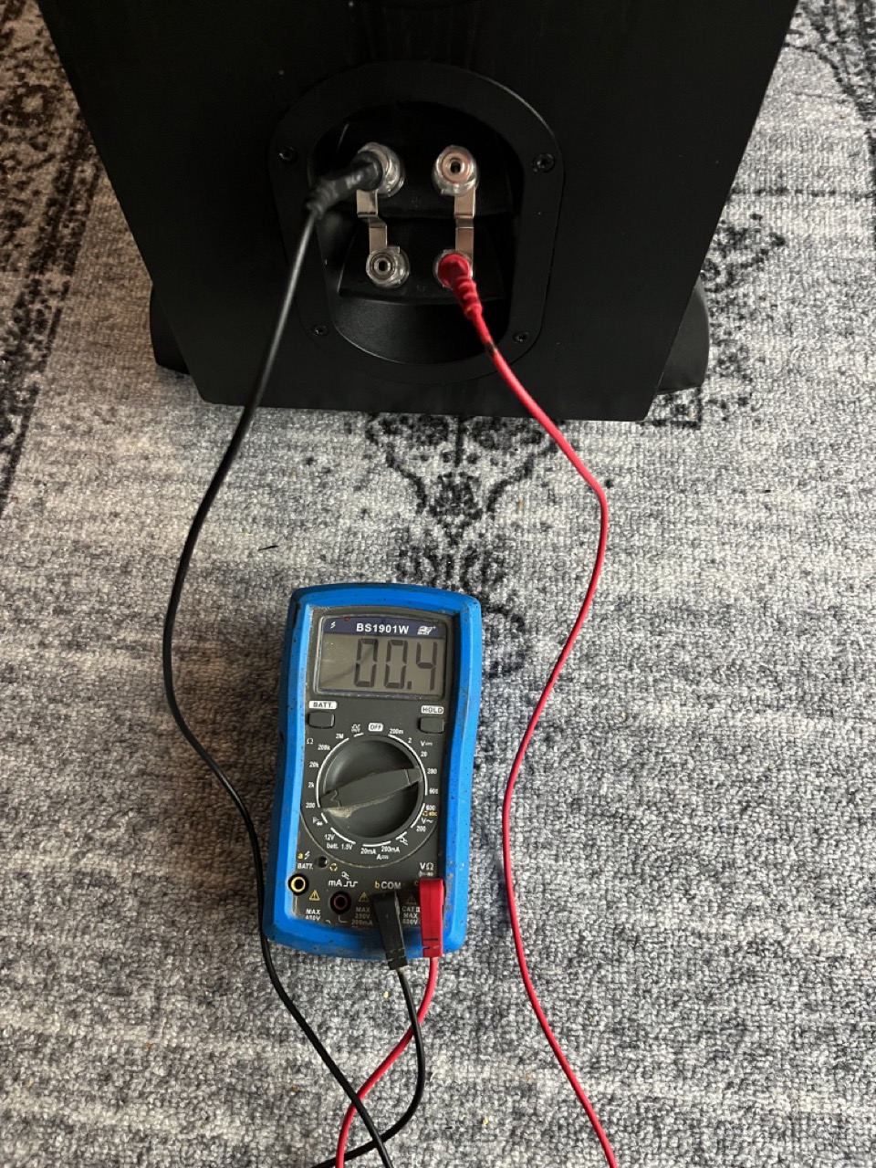
What's the measured impedance/resistance at the speaker binding posts when the crossover is installed and all the drivers are connected?
0.0.4
something isn't right
-
3 minutes ago, mboxler said:
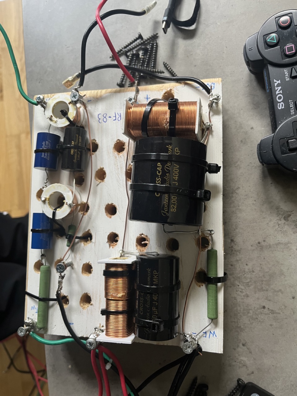
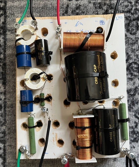
With the 8.2 ohm resistor "bypassed", the impedance of the woofer circuit drops to a dead short around 300hz. That's the resonance frequency of the 3.6mh in series with the 75uf capacitor.
I have desoldered and bent the wire upwards its not touching the resistor, I tried to measure the ohm impedance again its the same, on both 0.0.4 on speaker terminals I have them all connected on the floor drivers and crossover , should it not be about 8ohm total impedance on terminals all connected together ?
-
3 minutes ago, mboxler said:
You don't want a connection there. Can I assume that wire then goes to the - terminal at the top of the picture?
yes it does its one of the ground cables you pointed out I put on
-
14 minutes ago, mboxler said:
Is this a solder joint (red circle)?

yes it is
-
ok I have measured all the drivers from both speakers , all measure about the same so its nothing to do with the drivers, is there polarity on the coils? there is no polarity on the caps and resistors I used, can someone go over the crossover I built it should be right, im at wits end, maybe I should have just bought a second hand crossover
-
5 minutes ago, winglet said:
All 4 drivers measure like this?
yess it fluctuates but it settles at 0.0.4

-
with the same measurement ohms and 200 settings on multimeter as I measured the other drivers
-
7 minutes ago, mboxler said:
What ohm reading do you get on the drivers in the speaker with the new crossover?
it goes from 1.2 ohms at first and down to 0.0.4
-
I measured the drivers from the other speaker , the only reading I could get was in ohms and a 200 setting, tweeter 5ohm, and the bass drivers 9.7 ohm each
-
2 hours ago, mboxler said:
On the speaker with the new crossover, disconnect the speakers from the crossover and measure the DCR from the + wire through the tweeter to the - wire.
Do the same with the woofer(s). Hopefully there isn't a short of some kind.
ok so how do I measure DCR what settings on a multimeter, I tried searching around
-
I have only 1 speaker hooked up to my amp with new crossover,
-
14 minutes ago, mboxler said:
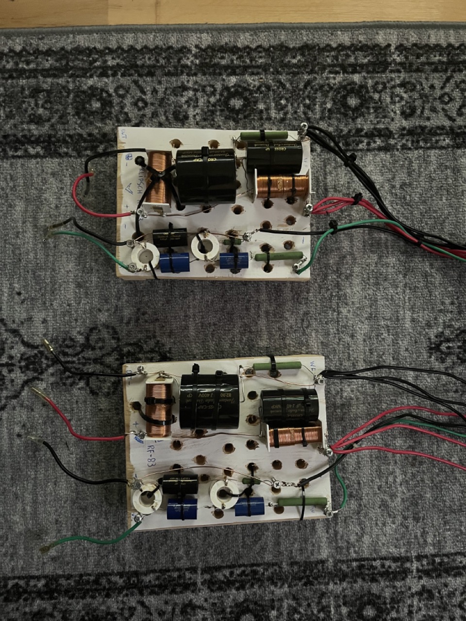
Hmmm. Can you post another picture of the new crossover?
Also, it might be a good idea to measure the DCR of the voice coils on all your drivers. Perhaps whatever damaged your crossovers also damaged a driver.
-
On 5/14/2023 at 3:39 PM, mboxler said:
Looks to me you are missing a common ground wire on each circuit. I assume the bottom of the picture is input? If you run another black wire from the bottom right screw to the top right inductor (where the other black wire is connected) the woofer circuit should work.
Likewise on the tweeter circuit.
Unless you connected them underneath the board???
Mike
hello again, I has attached ground on tweeter and bass section, its still cutting out when pushing the volume, maybe I have changed the impedance of the whole speaker ? im using a Yamaha a-s1200
-
thanks for the help mboxler, I have only used the speaker once with the amp, Im now in the process of disassemble and attach ground
-
I have posted this if you care to take a look at it
regards K
-
hello I built a new crossover for my Klipsch rf-83 my old crossovers was burnt on 2 of the boards, I just need to double check if this is right, probably not.
its coming sound out and the speaker lacking a little in bass, but when I push the volume up the amp cuts out, I followed this crossover schematic I just used the leads of the caps and resistors and. coils mostly, it doesn't look pretty I used the stock coils from the bad crossover boards, regards
-
hello again, i have built my own crossover for a set of speakers Klipsch RF-83 with new parts I followed the schematic. but when the volume and bass is set, the amp cuts out, do you have an email I can contact you to get you to look at the crossover if something I did wrong? , looks like you know your crossovers for Klipsch, if you can
-
what measurment gear are you using?

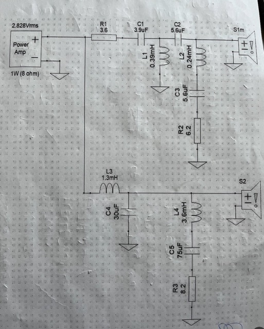
help with new made Klipsch RF-83 crossover build, amp cutting out when volume is increased
in Technical/Restorations
Posted
I got 2 used stock crossover boards for the bass section mine was burnt up, so I took the parts on that instead, speakers are back together") thanks for the help anyway
thanks for the help anyway