


Yankee Frank
-
Posts
29 -
Joined
-
Last visited
Content Type
Forums
Events
Gallery
Posts posted by Yankee Frank
-
-
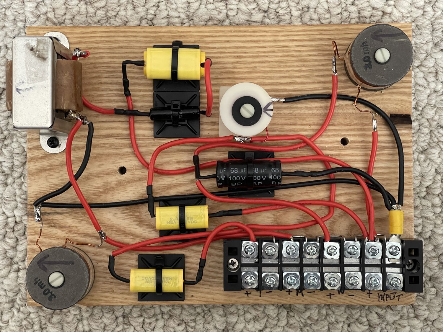
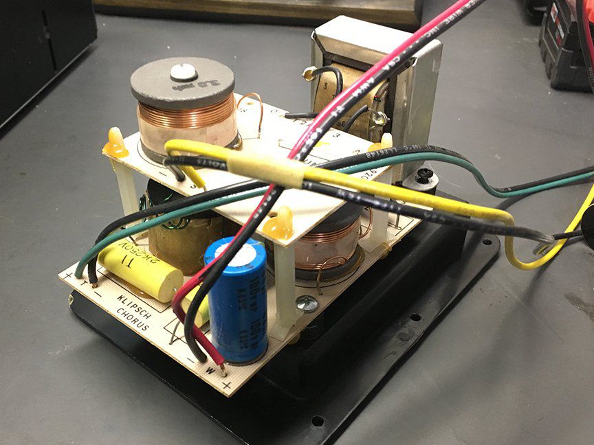
Here is my first Chorus 1 re-capped crossover. Let me know if you see anything that doesn't look right, before I put 'em in!

-
 2
2
-
-
1 hour ago, 001 said:
the JEM kit are composed of klipsch original capacitors , it's a plug and play solution for restoring the klipsch signature sound , and a search on the forum will show that all forum members who used them are very pleased .
Received mine from Jim at JEM and in the process of doing my Chorus now. I like the idea of going Klipsch supplied parts!
-
 1
1
-
-
https://rochester.craigslist.org/ele/d/rochester-klipsch-kg4-vintage-speakers/7434922767.html
No affiliation or interest.

-
1
-
-
On 1/17/2022 at 11:21 PM, tigerwoodKhorns said:
I finished the Forte crossovers with the caps mounted on a board. Posted pics in this thread. I will do the Chorus next.
Turned out well! Looking forward to seeing the Chorus... I have almost received all the components I will need.
-
30 minutes ago, Crankysoldermeister said:
I would tell people to pack like the box is being dropped kicked across the country, which it will be. Wrap in large bubble wrap, and pack dead spaces so networks don’t shift - with more bubble wrap or newspaper. No peanuts.
I am with you on this, but after getting his email I have resigned myself to doing it myself. Just need to wait for the parts to be in stock again.
-
3 hours ago, Crankysoldermeister said:
Maybe supply shipping instructions?Per JEM: Shipping services today are extremely rough on the packages and getting a claim for damages settled is an experience you want to avoid at all cost. Due to this situation, I am not offering installation service for the networks that contain circuit boards.
-
7 hours ago, Curious_George said:
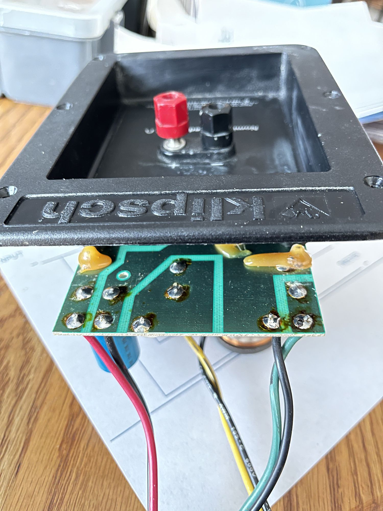
These PCB’s are definitely not multiple layer. Just single-sided.
Thank you. Never saw or heard of a PCB configured that way.
-
16 hours ago, RandyH said:
you're better off , sending the crossovers to @JEM Performance , they are the klipsch USA crossover repair center , they only use Klipsch Original capacitors for the optimal sound quality .
-2nd option is for you to purchase klipsch capacitors which you .......or a technician can solder -VIP , the capacitors MUST fit the crossover or it becomes a mess -do it right and you'll have great sounding speakers for the next 30 years - .
I already tried JEM, Jim doesn't want me to ship PSBs because the shipping process has damaged others that were either headed to him or back to the customer. Now, after reading a lot of other posts on the topic, I most likely will be buying their capacitor kit, since it is Klipsch approved. Unfortunately their Chorus capacitor kits are out of stock until (about) late Feb. Put the crossover back in today until then, I can't listen to the JBL 530s another minute longer if I don't have to!
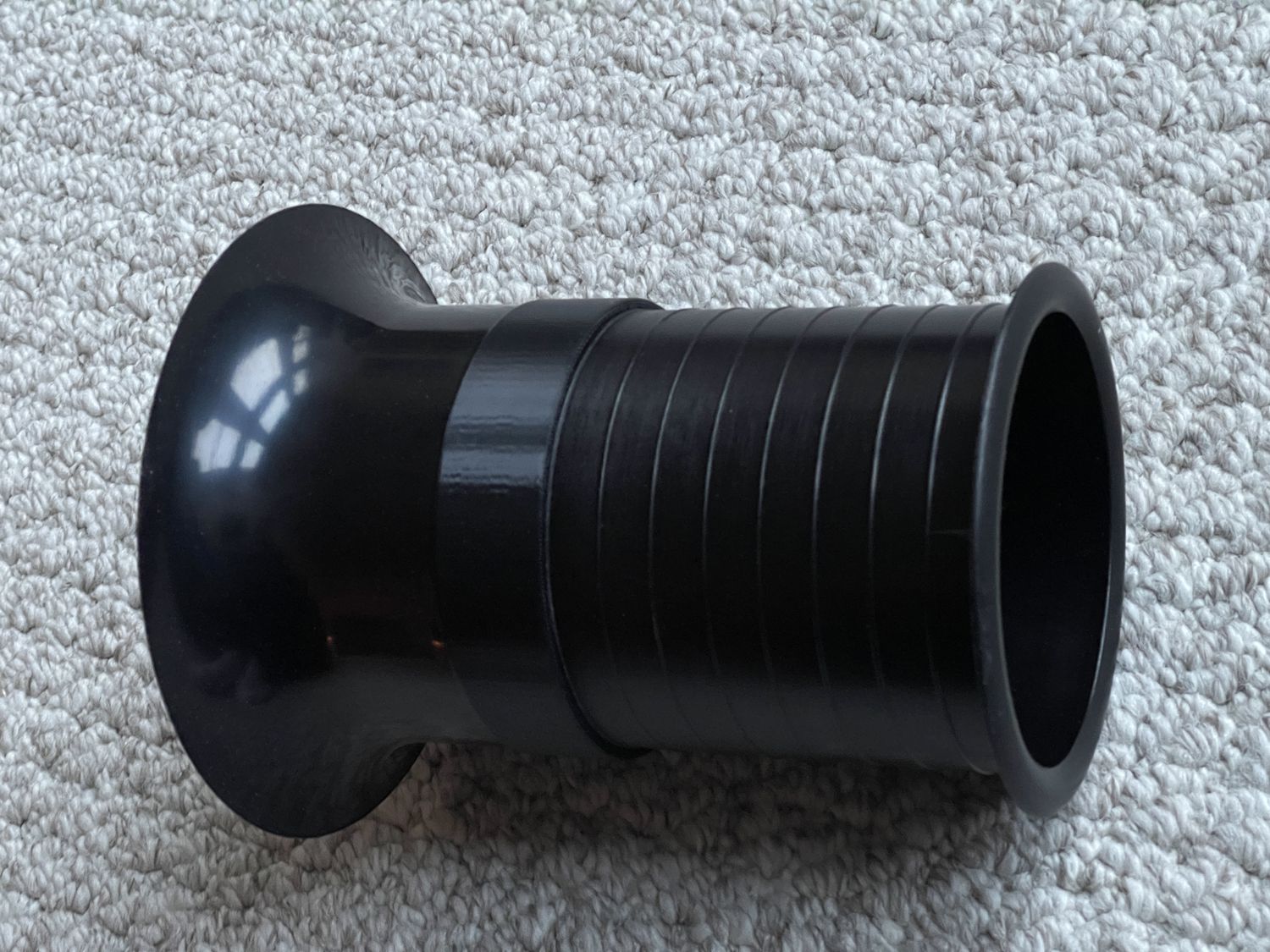
Loosening the autotransformer made crossover extraction and re-insertion MUCH easier and I was also able to install the port tubes from Parts Express while I had the 15" K48 out. I grew a thin union collar on our 3D printer at work to couple the 2 halves.
-
On 1/7/2022 at 6:31 PM, Yankee Rebel said:
So my questions thus far are these:
1) Is this what is really going on with regard to the PCBs? (zoned areas)
2) Is there a preferred type and gauge of wire I should use on the crossovers?
3) Has anyone else here done this for first generation Chorus before, and if so, would you have any pictures or tips to share, please?
My questions remain...
-
2 hours ago, billybob said:
Yes looks like my old Chorus crossovers. Glue holding the
top psb in place. Used Clarity caps, a Bennic, and 1 Mills resistor.
Saved the old caps.
Did you use the 1.8 uF and 6.8 uF Clarity instead of the 2.0 and 7.0 uF?
-
49 minutes ago, tigerwoodKhorns said:
I am doing this right now on Chorus II and Forte IIs (just received my last caps yesterday).
No need to discard the printed board. In fact, it will keep everything nice and organized. I plan to remove the printed board, attach it to a piece of wood, and then add my new caps elsewhere on the board to keep it all nice and clean. I will add jumpers from the speaker input plate to the board.
I can take pics when I have it all laid out and done. I did a pair of JBL L100Ts years ago. I attached a picture to give you an idea of what I am talking about. The white and blue wires were added by me down to the caps.
FYI, I am using Jantez caps from Partsexpress and electrolytes for the woofer bypasss.
Thanks for the alternative idea Tiger! I will think about how to un-sandwich the sandwiched boards to possibly achieve the results I am looking for. Not sure if Chorus II had the same sandwiched configuration as shown in the Chorus I photo.
-
2 hours ago, oldred said:
New to recapping crossovers...
I've done Chorus, Chorus II, Forte, Forte II, Heresy, Quartet, KG... All of them... Best thing for you to do is contact Crites and buy a crossover kit.... You can either get a Dayton kit or a more expensive Sonicap kit. You will need at least a 40 watt soldering iron (pencil), a damp sponge, solder, solder wick and a hot glue gun. Take your time. Make sure when soldering new ones in you get a nice solder joint around the terminal
George,
Thank you oldred. I do have a great Weller soldering station and the components I need will be ordered this weekend. I will work on my soldering joints!
-
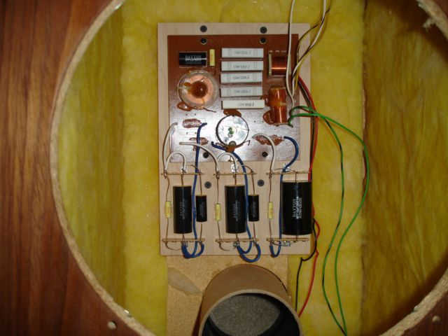
Hoping to get some help and insight for re-capping my Chorus. In the process I want to take out the printed circuit boards and mount the components similar to a Heritage type arrangement on a separate board. While I have the schematic, and believe I understand it, I am wondering if the existing PCBs are printed in a "zone" type arrangement, vs multiple layers and connections (see attached photo.). It looks to me as each "zone" has a non-conductive boundary around it and then various wires are soldered into that common area to connect the required components. So my questions thus far are these:
1) Is this what is really going on with regard to the PCBs? (zoned areas)
2) Is there a preferred type and gauge of wire I should use on the crossovers?
3) Has anyone else here done this for first generation Chorus before, and if so, would you have any pictures or tips to share, please?
Like I said, I believe I understand the schematic (although I wish I had a "road map")and have the skills and equipment to do the labor. I just want to understand the current configuration better so I do not to mess this up!
I will be taking the old inductors and autotransformers off off the PCB's and plan on replacing the capacitors and resistors. Once I have completed the first one, I will post another picture for review to make sure I didn't cross any wires!
Thank you for any advise or tips you might have!
YR
-
1
-
-
-
-
Thanks for the reply and all the good information!
-
I am going to do this port mod. Are you including the thickness of the 1" motorboard in the 7 to 7.5" length?
Thanks for your help!
-
-
All seems like an effort in futility... the seller does not seem to respond to any of it.
-
Dick,
We are all waiting for you to determine who has the first chance at these... I am ready to pick them up this weekend.
-
I am 2nd in line if they do not sell!
-
Dick will see that mine went out on the 2nd, at 10:50 PM.
by yankeefrank
05-02-2013 10:50 PM
-
So who has first dibs?
-
PM was sent out a while ago, please let me know if you still have these for sale.
Chorus crossovers
in Technical/Restorations
Posted
Link for wire is https://www.amazon.com/gp/product/B0975M7X3L/ref=ppx_yo_dt_b_asin_title_o01_s00?ie=UTF8&psc=1
I (obviously) have a lot left over. PM me your address and I will send you plenty to do yours and be happy to save you some $$.