


mboxler
-
Posts
574 -
Joined
-
Last visited
Content Type
Forums
Events
Gallery
Posts posted by mboxler
-
-
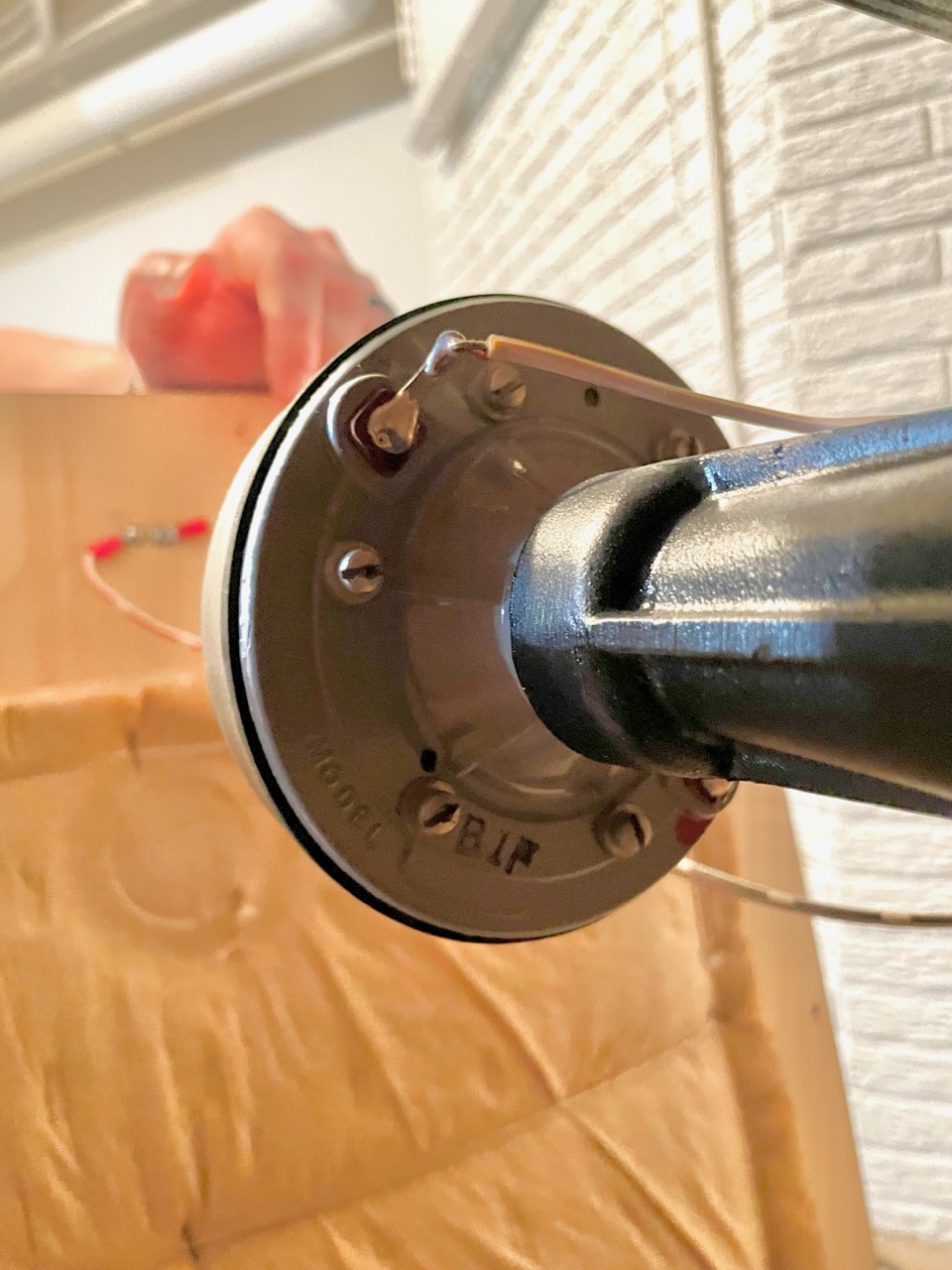
2 hours ago, salbake said:

Looks like you got the rare dual phase plug K-55V with solder lugs!
-
 2
2
-
-
Correct me if I'm wrong, but phase can play into this as well.
My memory may be fuzzy, but if an amplifier is driving a load with a -45 degree phase shift, only 70% of the supplied power is transformed into work. The remaining power is reabsorbed by the amp and dissipated as heat.
In other words, to supply 100 watts of power to a driver @ -45 degrees, the amp will need to supply 140 watts and absorb 40 of those "unused" watts.
-
50 minutes ago, SpeedLimit said:
it will be hard for me to find T4A autoformer ..
I'm a little confused. Do you already have an AL-3 crossover? If so, it already has a T4A.
-
1
-
-
5 minutes ago, Deang said:
Yeah, but are you sure? Like really sure, lol.I'm not sure what I had for breakfast this morning 🙄
-
 1
1
-
-
22 minutes ago, SpeedLimit said:
Yes .. but the Atlas sound is given to go up to 4500 Hz if i remember..
Sounds like we are in agreement. If the Atlas is only flat to 4500hz, and the AL3 tweeter filter has a steep 6000hz high pass, then there would be a hole in the 4500 to 6000hz range.
-
The squawker is allowed to drop naturally on the AL3...there is no 6000hz low pass.
-
I've always assumed that when Klipsch went back to the single phase plug K55, they added a 4500hz low pass to the squawker (AL4) to avoid the high frequency "shortfall"???
-
5 hours ago, SpeedLimit said:
Maybe the question has already been asked, but I haven't found on the site.
For which Squawker, was the AL3 crossover (La Scala) planned? ==> For the K55 Electrovoice or the K55 Atlas Sound PD-5VH?
The 2 drivers do not have the same usable frequency band .. The Atlas sound is a little bit short in the high frequencies compared to the Electrovoice
The dual phase plug K55M is flatter to 6000hz, then drops like a rock. I assume this required the change from the AA type tweeter filter, which crosses closer to 5000hz, to the steep elliptical filter in the AL and AK series crossovers that cross at 6000hz.
I would think that a K55V solder tab would work as well in the AL/AK crossovers, since it also is a dual phase plug.???
-
On 3/30/2023 at 1:47 PM, Dave MacKay said:
Like @mboxler, I'm confused too.
I've been trying to understand how the 1st order filters used in the woofer section of the A and AA networks work. The filter consists of just a 2.5 mH inductor. When I calculate the crossover frequency into the K-33E (which is rated at 4 ohms), I get a crossover frequency of 250 Hz, not the 400 Hz that I was expecting.
Even if the K-33E was 8 ohms, the filter would crossover at 510 Hz, not 400 Hz.
I know that driver impedance isn't constant, and that it varies with signal frequency. When I vary the woofer impedance based on a curve that @Trey Cannon posted sometime ago, I find that the crossover frequency varies between 220 Hz and 1210 Hz in the frequency range applicable to the woofer.
I had hoped for a nice clean drop-off starting at a specific frequency, but that doesn't seem to be how the filter works.
i thought that higher impedance = higher crossover frequency = more attenuation = lower SPL but that's not what my REW measurements show.
I must be failing to understand something. What am I missing?
As I understand it, there's a lot going on regarding the impedance of a K-33E in a Klipschorn...
Voice coil DCR
Voice coil inductance
The loading of the horn itself
Other things???
Bottom line, the impedance at 400hz ends up being around 6 ohms @ 28 degrees. That's equal to a 1.1mh inductor with 5.2 ohm DCR. At 800hz, it's 8 ohms @ 40 degrees, which equates to a 2mh inductor with 6.2 ohm DCR. It's a moving target that I assume shows up in your REW measurement.
Mike

-
1
-
 1
1
-
-
It looks like a hybrid Type A/Universal. The black inductor is probably 2.5mh(?). Can you read the capacitor values on the left side of the picture? I'll guess they are 2.2uf and 6.8uf? Are there any labels on the black and red inductors that indicate the values?
-
Looks like AP-350's.
-
1
-
-
12 hours ago, Escoffee said:
I swapped phase on my squawker today and retested. Seems like it was reversed which is odd, I don’t see any markings on it and the wires visibly are now backwards left to right. I suppose the back cover could be glued on upright and the connectors just rotated?
anyhow! The drop in 3-600hz is thankfully gone. Audibly better as well. This test compares original crossover to the jem kit installed properly (now).
I don't see any obvious wiring errors. Perhaps the issue was with the woofers instead of the squawkers. It is a little hard to see inside the bass bin.
-
3 hours ago, Escoffee said:
Not sure why the dip between 3-600hz (thoughts?).
That's the crossover frequency from the woofer to the squawker. Any chance you may have accidentally reversed the polarity to either of the drivers during the switch?
-
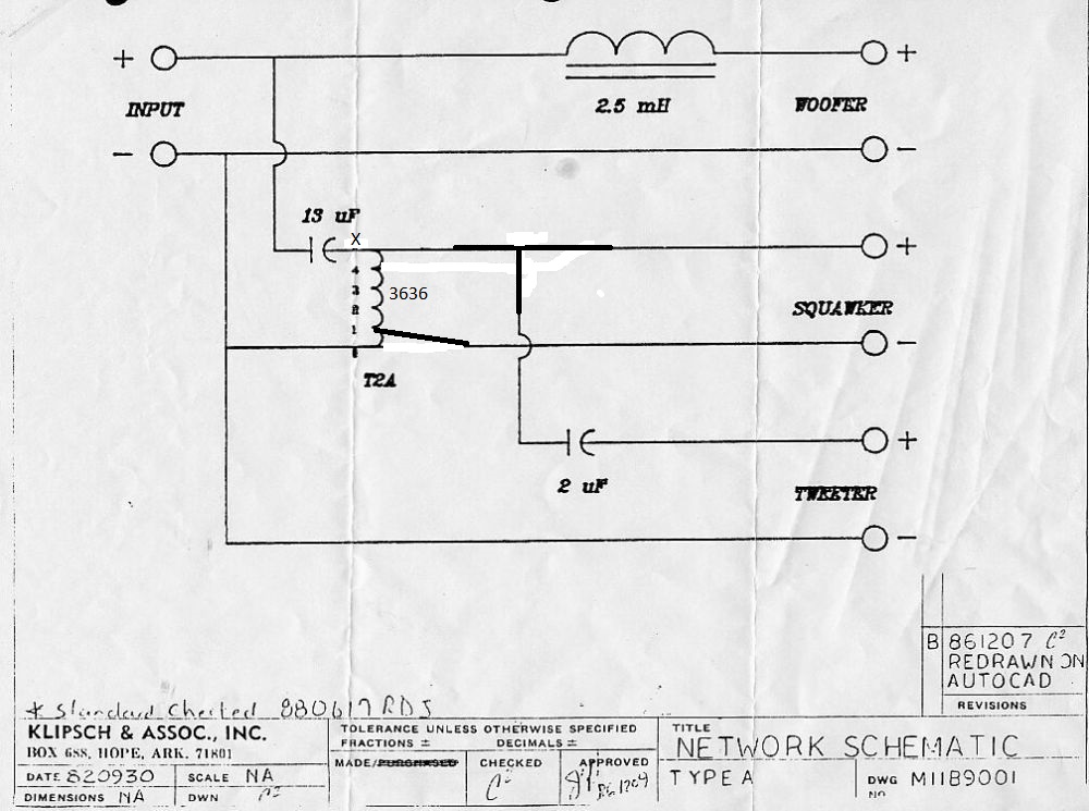
On 2/17/2023 at 8:18 PM, Ezwind said:
I'm a newbie putting together some homebrew La Scale and need the proper 3636 pin out for a simple type A crossover. Thanks for your help.
Depends on what you mean by "proper" 🙂
Crites will use input taps 5 - 0 and output taps 4 - 0 to achieve a 3db attenuation to the squawker. The T2A's tap 4 used in the Klipsch Type A is actually -3.3db. If you want what I would consider proper, use input taps X - 0 and output taps X - 1. This will get you -3.3db and get you really close to the inductance of a T2A. Hopefully my poor drawing helps. Notice that the tweeter circuit now uses input taps X - 0 and output taps X - 0.
Mike
-
1
-
-
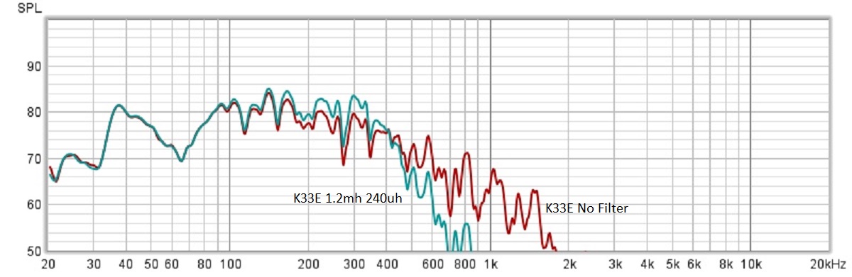
2 hours ago, Invidiosulus said:
Isn’t the mass roll off frequency on a K33 typically around 180Hz?
Looks like it. I'm playing with a severely underdamped filter consisting of a series 1.2mh inductor and 245uh worth of capacitance across the K33E. Seems to create a much flatter response up to 400hz compared to no filter at all.
-
1
-
-
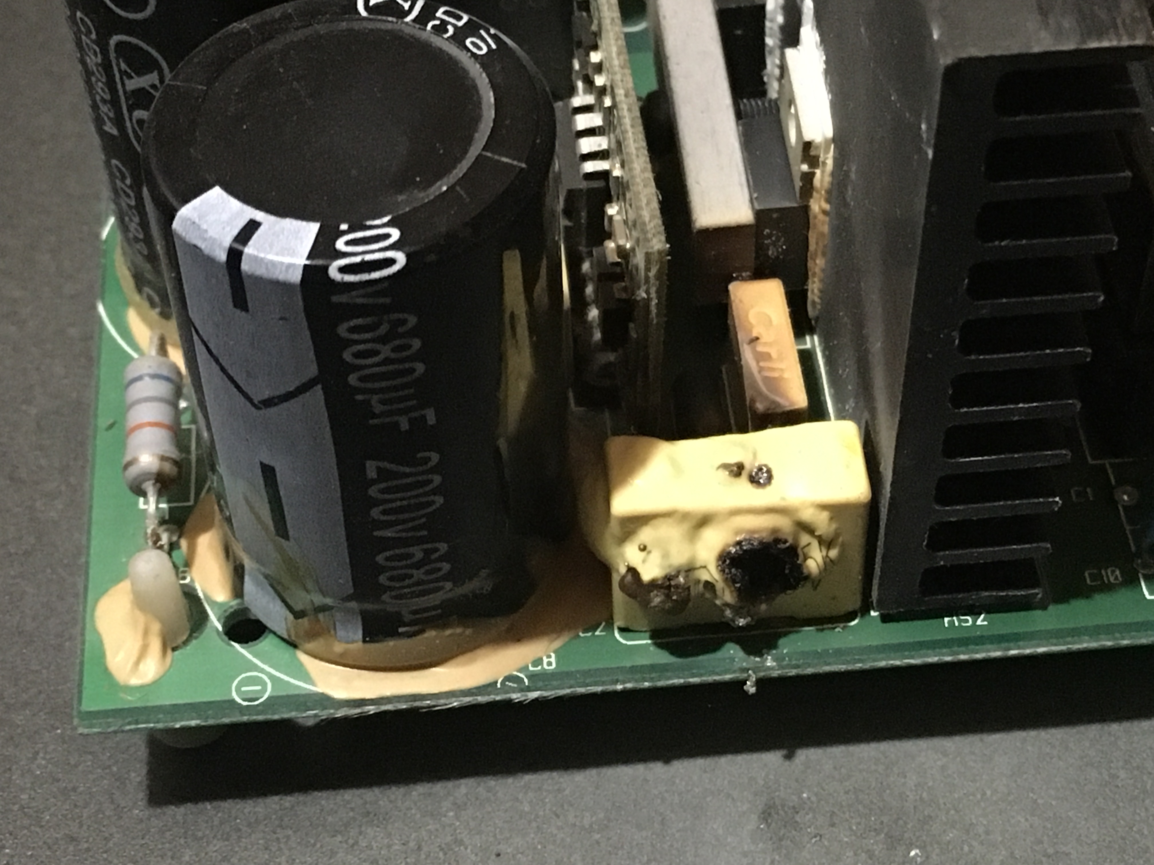
2 hours ago, Griggsfamily55 said:
I reciently hooked up my RSA-500 to a new sub. Unfortunately the sub wants a little more power than this amp can push. There is a component on the power supply that i cannot identify due to a hole through it. Can anyone with this amp please help me identify this component. It is one of the square yellow ones on the power supply board, specifically the one closest to the front of the amp.
Thank you
That looks like C2 on the pcb, so it's probably a capacitor. Hopefully you can remove it and find some legible markings to identify it.
-
1
-
-
4 minutes ago, geoff. said:
@mboxler, what tweeters are you used to listening to in your La Scalas(?)?
Within the past couple of months I built a pair of polyester capped AAs as a reference to compare other crossover builds to.
I am trying to assemble a second set of La Scalas to loan out to friends and family so they can see what the fuss is all about. Trying to keep it as close to original as possible, but after listening to aftermarket tweeters for years now I couldn’t get the K-77Ms to sound right either.
They are Khorns 🙂, but I've been listening to CT-125's. They are at least 6db quieter than the K77M.
-
1 hour ago, Klipschguy said:
1981 Klipschorns came bone stock with the K33E, K55V (dual phase plug), K77M, and AA crossovers. Mine sound very smooth and well balanced without even a scintilla of sibilance. In fact, if anything the tweeter sounds very slightly recessed in the mix (big room, hardwood floors, high ceilings). My Cornwalls (in a different room) sound a tad brighter yet they have the K77 alnico tweeters with the B network.
As you know, room differences can make a big difference in frequency response. I have a grand piano in a smaller room that did not sound its best, so I used a number of room treatments including drapes, an acoustic panel, and a rug; it took a little experimenting but the room went from pretty bad to great. My piano tech liked the results very much and commented “it is better to treat the room rather than the piano.”
Respectfully,
Andy
Thanks, Andy
That kinda blows my theory out the window. I'm very tempted to buy a pair of alnico K77's just to see what's going on.
-
1
-
-
Thought I'd post my conclusions here for so I can easily find my results.
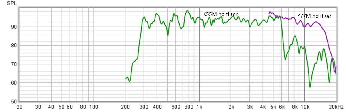
Like Dean said, it appears that the AA Network was designed for the K77 alnico tweeters. Research indicates that the K77M is hotter than the K77. I'll assume the AA was also designed for the K55V single phase plug drivers, as they are not as flat as the K55M from 4.7 to 6khz(?). Again, I don't have these drivers, but I'll assume my AA build is correct for the K55V/K77 driver combination.
I am surprised how hot the K77M is. I finally got the idea to measure the raw frequency response of the K55M (200 to 20000hz) and the K77M (4500 to 20000hz). Around 4.7khz the K77M is actually 1db hotter than the K55M. The tweeter circuit of the AA isn't designed to handle the K55M/K77M driver combination. The steep slope of the AK tweeter filter, on the other hand, knocks off most of the voltage to the K77M below 6500hz.
Mike
-
1
-
1
-
-
15 minutes ago, mark1101 said:
Now this looks significantly more correct for an AA decay of the K77M compared to Sweep 3 above.
Would you agree that it's odd that the SPL graph on Sweep 3 is different than the voltage graph?
-
13 hours ago, mark1101 said:
Something doesn't look right with the K77M having so much energy below 6K. Sweep 3.
Are we sure the AA network is operating correctly?
I believe so. This morning I ran a few more tests to ease my mind.
My LTSpice model vs the REW plots come out very close. One thing that's difficult to model is the K77, as I believe it resonances in the 4 - 5khz range. I'm not smart enough to determine if that's why the SPL peaks sooner than the voltage.
I appreciate all comments. Perhaps I'll install new diaphragms and try again.
Again, thanks.
Mike
-
30 minutes ago, BeFuddledinMn said:
@mboxler - excellent work and observations. While the midrange and tweeter issues between network and driver variations are more well known, the woofer to midrange transition in a KLIPSCHORN is less understood. Your woofer polarity swap with a gentle 6db slope network is a great example.
It would be great to get Chief Bonehead’s insight on that issue.
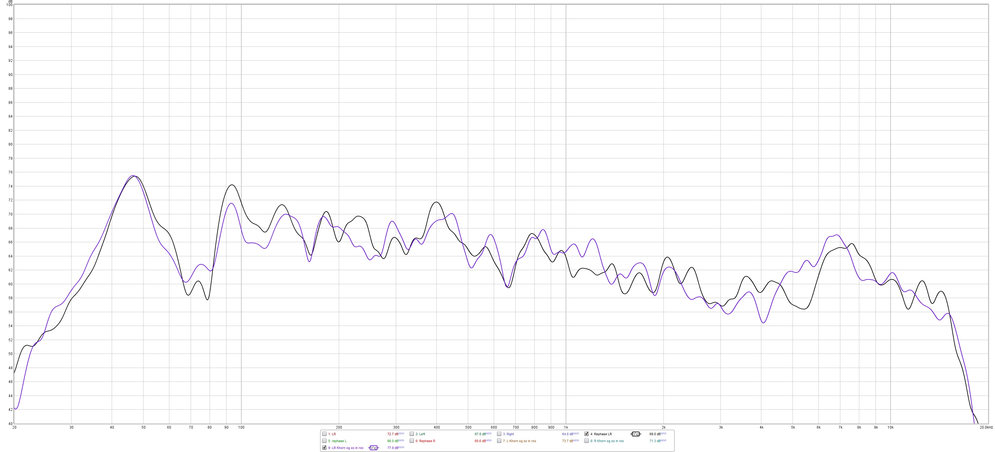
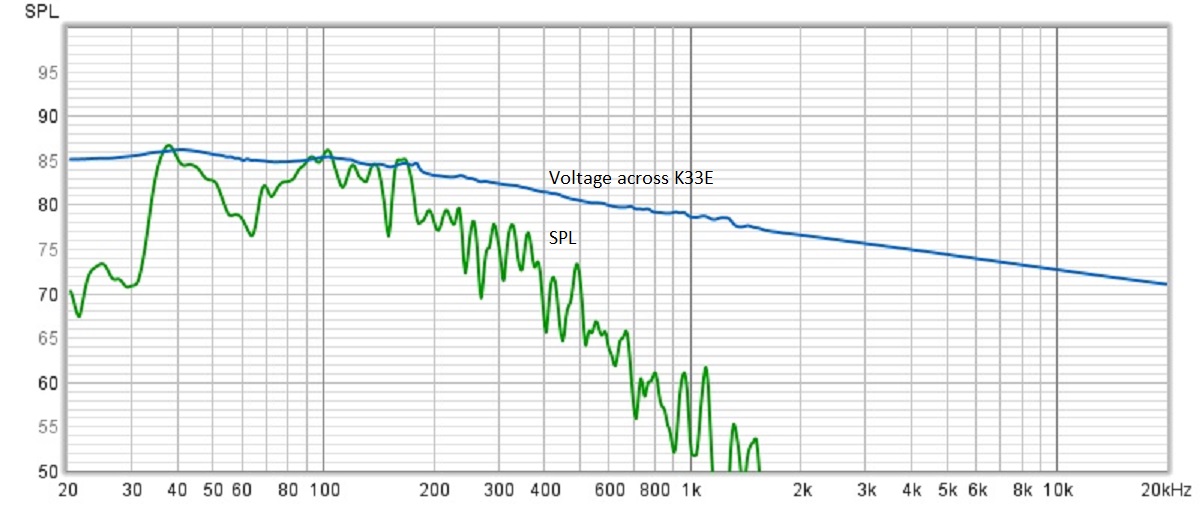
Thanks for the kind words. Your post is a great seqway to another measurement I took this morning (sorry Dean 😎).
Without a zobel across the K33E, there's really no way to achieve a classic first order 6db per octave low pass. The inductance of the voice coil continuously raises the impedance of the woofer as frequency increases. With a series 2.5mh inductor, the result electrically is a much flatter transfer function (blue plot). Then there's the SPL itself. Even without an inductor, the SPL drops dramatically after 180hz. In my room, with a 2.5mh series inductor, the SPL is down around 12db at 400hz (green plot). I believe this creates my dip in frequency response between 160 and 410hz???
Mike
-
1 hour ago, wvuvt1 said:
I could be wrong but on the back of the fives you can switch from phono to line, allowing an analog input other than a turntable?
That's confusing but you may be right. I assumed the switch dictated phone or aux. The manual isn't very clear.
-
9 hours ago, wvuvt1 said:
There is some debate on other threads about being able to bypass the dac on the fives by using an external dac
My thinking is, If I have an external dac, say the blue sound node and use the analog inputs on the fives (like the phono input) how is this not bypassing the internal dac, the signal the fives are receiving is analog ?
Without a schematic it's impossible to know. That said, it appears that the fives use DSP for crossover/equalization. If that's the case, I would think that an analog signal would first need to be converted to digital, processed, then converted back to analog. An input digital signal would not necessarily need the extra ADC step.
FYI, don't connect anything other than a turntable to the phono jacks. A phono preamp is expecting the very low voltage generated by the phono cartridge which then gets amplified/corrected to a line level voltage. Use the aux input for line level input signals, such as your DAC.
.png.a67644f05052479ba1876793e3c5b442.png)

.png.ae152687864ba2a5f68e96d1f33066a3.png)
Crossover Values
in Technical/Restorations
Posted
Poking around on the Web, it looks like there is a switch on the front to control the tweeter? Perhaps it's a variable series resistor to pad down the tweeter? Also, sounds like the original capacitor was a 2uf non-polar electrolytic. If so, it's probably dried out and not functioning properly.
I'd replace the capacitor with a 2uf polypropylene, and check the switch to make sure it's not faulty.
BTW, a 2uf capacitor at 2500hz is around 32 ohms. The switch could be adding 24 ohms to an 8 ohm load to achieve that crossover point.
Mike