xrk971
-
Posts
14 -
Joined
-
Last visited
Recent Profile Visitors


xrk971's Achievements
Member (2/9)
2
Reputation
-
University Classic/Dean Horn profile need driver choice help
xrk971 replied to moray james's topic in Technical/Restorations
Nico, First of all, let me say that your build /mods of the Classic look fantastic. The deeper bass has more to do with the length. The aperture or throat in front of the driver affects the HF extension in combination with the size of the front chamber and rear chamber. Get a mic. Even a cheap one is better than nothing. If all fails, use the built in mic on your laptop. This one is only $16 and fits your phone. http://www.parts-express.com/dayton-audio-imm-6-calibrated-measurement-microphone-for-iphone-ipad-tablet-and-android--390-810 -
University Classic/Dean Horn profile need driver choice help
xrk971 replied to moray james's topic in Technical/Restorations
Edgar, That looks great. Can you point me to which plan you used for the dimensions in the model? -
University Classic/Dean Horn profile need driver choice help
xrk971 replied to moray james's topic in Technical/Restorations
Grindstone, Thanks for the comments and questions. I think that this horn has 50Hz output and plenty of it - it's just 10dB down from the max level and for something that can hit 130dB peak 120dB is still no shame. I actually like this horn and think more people should like it for what it can do to reach the upper bass and mids to integrate with a mid horn. Given that the path length is what it is and Hornresp and Akabak have similar predictions I would have to say I trust the sims as accurate. Until someone provides measurements, I just can't see how this box has a corner frequency anywhere close to 50Hz. The boxes (especially FLH and TH's) I have modeled - the corner frequency is very close to measured - within less than 5Hz. It's really the physics of the 1/4-wave length. No corner reflector or compound oblique angle walls near the throat is going to change that. It may affect ultimate SPL or flatness but not extension. I could easily put a corner reflector but my experience tells me it is a negligible effect given we are looking for deeper bass. X -
University Classic/Dean Horn profile need driver choice help
xrk971 replied to moray james's topic in Technical/Restorations
Djk, Interesting design there. For push pull to work properly doesn't there have to be symmetry in how they are mounted? The rear chamber of the top driver also needs to be same volume as the triangular chamber of the bottom one. Also, the goal of having a higher xo point to reach a 1in CD would mean being able to go up to 1kHz. Above 500Hz, sounds going through sharp corners, magnet baskets, and reflecting off narrow throat channels won't sound good - too colored and reverberant. I had a great folded bass horn that worked in the 30Hz to 300Hz range. I made a mid version of it by scaling it smaller to go from 100Hz to 1kHz. It sounded awful - nasally and reverberant. All the corners and narrow passages and reflections on the many turns. Mid horns need to be round and smooth. -
University Classic/Dean Horn profile need driver choice help
xrk971 replied to moray james's topic in Technical/Restorations
Yes, I come from the sub woofer forum on diyAudio and there, they are all about Max SPL. Probably a 50 watt woofer is all you ever need. I built a full range tractrix synergy and it is so efficient that I never turned it up past 10 o'clock as it was too loud at 108dB at 1 watt. http://www.diyaudio.com/forums/full-range/261427-presenting-trynergy-full-range-tractrix-synergy.html -
University Classic/Dean Horn profile need driver choice help
xrk971 replied to moray james's topic in Technical/Restorations
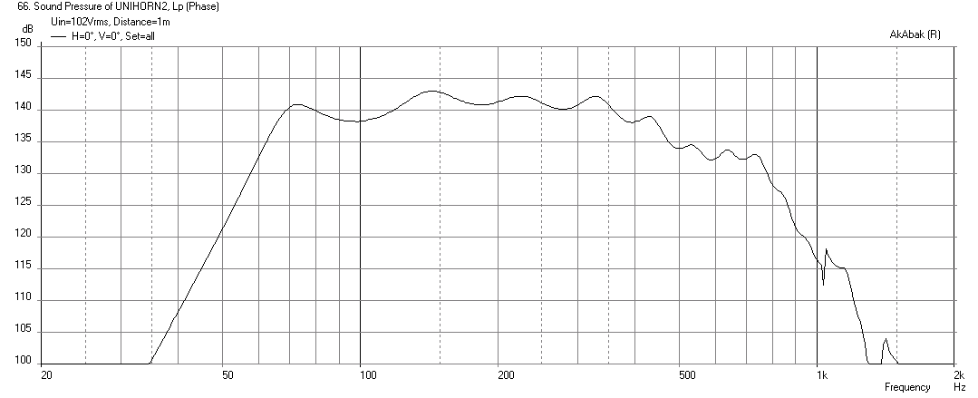
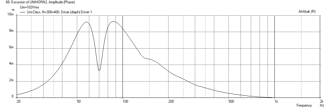
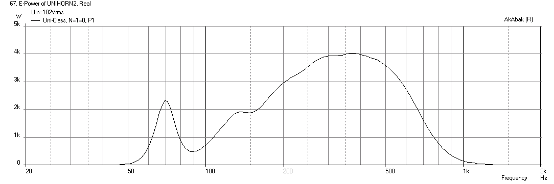
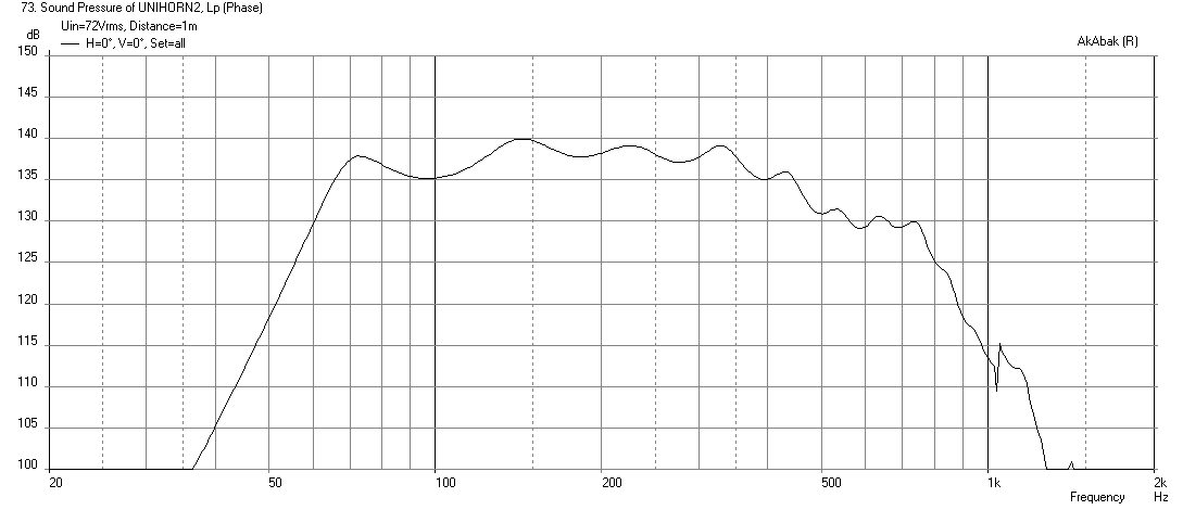
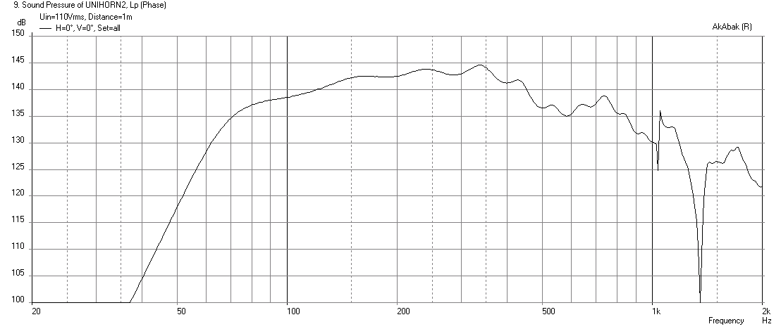
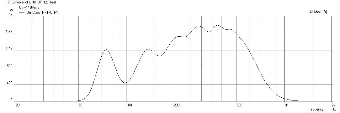
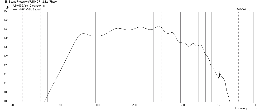
You want dual drivers? I'll give you dual drivers... hehehe... One of my favorite 12in sub drivers is the Faital Pro 12HP1030, rated at 2kW peak, 1kW rms, with 12.5mm xmax and 95dB sensitivity. Let's put two of these in parallel for 4 ohm nominal load. Increase the throat from 13in tall to 26in tall, and increase the height of the first segment of the horn appropriately to 26in tall expanding to 30in tall at the corner and skip the compound curves (which I argue are not even necessary for a good single driver design). I still like running max SPL sims because as a pro audio sound reinforcement system, that is what it's all about. For home use, you don't need drivers and horns like this as 10 watts would have the cops calling. Ok, so here is the predicted peak SPL limited by 4kW (max) thermal rating: This is some serious SPL with 140dB capability from two 12in drivers in a single box. This is the corresponding cone displacement, only 9mm of the 12.5mm allowed: And here is the electrical power input. As usual, 24dB/oct LPF and HPF are used at 60.5Hz and 700Hz, respectively: For sustained max SPL, we limit the drive to 72 volts RMS for 137dB - still pretty crazy high: Yes, window frames and plaster walls would all be obliterated inside a regular home if this was applied. Kind of like a demolition machine for renovation work...
-
University Classic/Dean Horn profile need driver choice help
xrk971 replied to moray james's topic in Technical/Restorations
I think if you line the chamber with enough egg crate foam on all walls and add some polyfill, it probably won't "see" any of the parallel walls. In reality, with appropriate padding and stuffing the output should be smooth. Ok, no more math today. Does anyone have measurements of a Classic to see if the predicts here are reasonable? This is a pretty simple horn so I trust Akabak pretty much on this one that it is correct, as long as I put in the correct geometry. I am pretty amazed at the SPL's this thing can reach if thermal loading was not an issue. On the B&C driver, it is only getting to maybe 7mm for a 13mm xmax driver - but topping out on the 1800 watt rating at 7mm. -
University Classic/Dean Horn profile need driver choice help
xrk971 replied to moray james's topic in Technical/Restorations
Thanks for the drawings Grindstone - great to see actual University blueprints! I found a mistake in my area, your so-called, "hard number to get". Isn't that just the area of a trapezoid which is the average of the parallel edge lengths times the height? Or 0.5*(13.00+16.27)*6.25=14.63*6.25=91.47 square inches? Your drawing shows 112 square inches. Anyhow, I reran the sim with 91.5 square inches and 80 liters rear chamber with an acoustical depth of 6.5in (will need baffles in there). This is with the original horn length (no additional stub). The output is much smoother now and reaches quite a high level when driven to xmax at 7.6mm with 110 volts. With a 65.5Hz HPF and 700Hz LPF (both -24dB/oct), this translates to a peak power of about 1.8kW. This driver is not rated for that high so probably compression and overheating would prevent such high SPL's from being reached. Now is the time to look for the expensive high end B&C monster drivers. Here is the predicted SPL at xmax with no LPF: Here is the predicted SPL at xmax with 700Hz LPF: Here is the predicted electrical power input with 700Hz LPF: Here is a B&C 15SW115 pushed to max thermal of 1800 watts (only half of xmax reached):
-
University Classic/Dean Horn profile need driver choice help
xrk971 replied to moray james's topic in Technical/Restorations
Ok, thanks for the careful calculation of the rear chamber volume. 80 liters it is then. -
University Classic/Dean Horn profile need driver choice help
xrk971 replied to moray james's topic in Technical/Restorations
The "doghouse" is the rear chamber? Based on the triangle height of 23.5in (derived from geometry of 67 deg isosceles triangle with a 18.375in base) the volume is = base*height*depth/2 = 6477 cu inches = 106 liters. I don't see how a driver would occupy 26 liters of volume - that is almost 1 cu ft of driver. What do you mean the models were wrong when you built it? It did not work as advertised? -
University Classic/Dean Horn profile need driver choice help
xrk971 replied to moray james's topic in Technical/Restorations
Edgar, That's interesting that you don't have all those back chamber reflections by your setting the Fr large. I am just in the opposite situation, I use Akabak so much that I have to re-learn HR everytime I use it. I find its notation very cryptic and confusing - like what is the back chamber volume and area vs the front chamber volume and area. Typically, I use more than 5 segments and often have complex multiple channel horns or drivers located at different locations (for example, a synergy horn with all 9 drivers and ports in a 3-way configuration with XO's). My biggest stumbling block with HR has to be the TS parameters - manufacture data is very straightforward to put into Akabak and I keep a running base of all TS params that I have used (over 130 drivers and counting) and can cut and paste instead of entering into dialog boxes each time, and not having to convert the manufacturer's standard notation to Cms etc. It's all what we are used to I guess. The PRV 15W1600 is 5.3 in deep, so I set the rear chamber depth at a practical 6,5in for clearance and still get some variation that is different from HR (plotted out to same 20kHz upper limit as you have) - I wonder if this is due to the extra folds? Of course, in reality, the woofer cannot move in pistonic mode up to 20kHz so it will follow measured response curve which falls off at 1.5kHz. Regards, X
-
University Classic/Dean Horn profile need driver choice help
xrk971 replied to moray james's topic in Technical/Restorations
Edgar, Are you applying a low pass filter? As you don't have all that higher frequency hash that I have. Thanks for the feedback and confirmation that my quick and dirty dimensions are within ballpark. There is another easy mod to this box that can really bring the fb down. Working on that now. X -
University Classic/Dean Horn profile need driver choice help
xrk971 replied to moray james's topic in Technical/Restorations
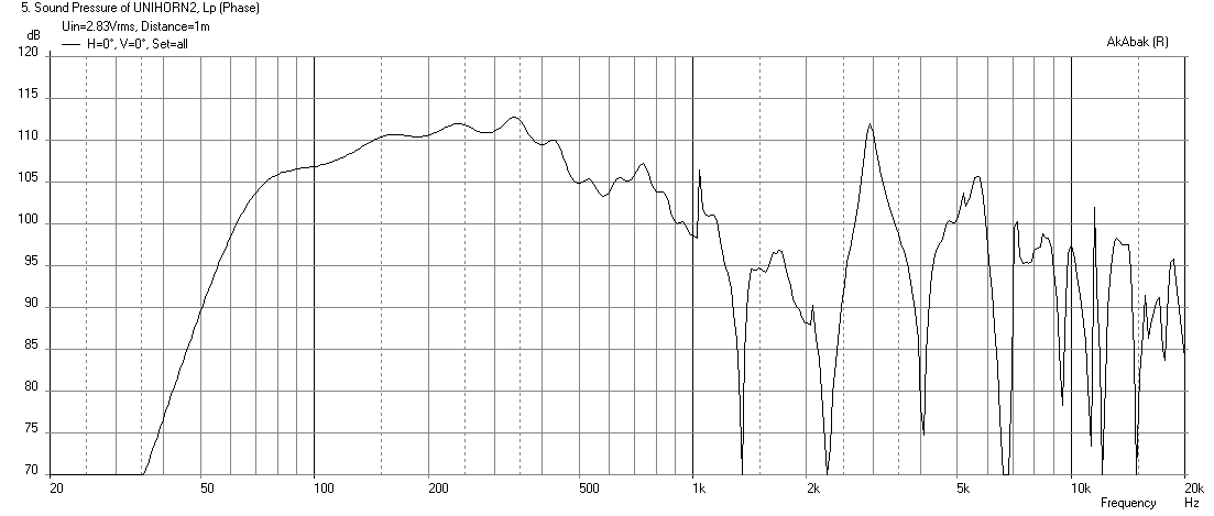
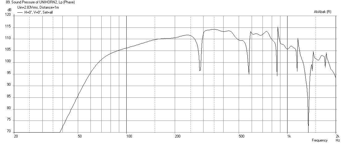
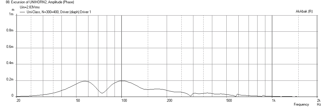
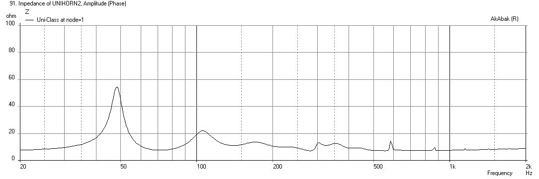
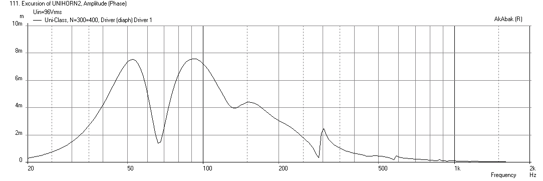
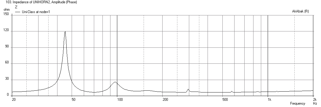
Here is the drawing that I got from Moray James with which I based my dimensions from for the model (shown annotated in color). I modeled it as 7 segments with starting and ending faces of the "waveguide" element shown in green. The distance (in red) units are in inches and refer to the cross-sectional areas and lengths. Near the throat, there is a 3d expansion and the height of the channel (nominally 30in) is shown in parenthesis and dark blue. Annotated sketch of model: Here are the driver parameters that Moray James provided me. Probably a University C15W dual VC driver as measured using DATS: * Piston Diameter = 330.2 mm * f(s)= 69.98 Hz * R(e)= 6.63 Ohms * Z(max)= 74.00 Ohms * Q(ms)= 3.708 * Q(es)= 0.365 * Q(ts)= 0.332 * V(as)= 91.420 liters (3.228 cubic feet) * L(e)= 1.41 mH * n(0)= 8.19 % * SPL= 101.20 1W/1m * M(ms)= 58.27 grams * C(ms)= 0.09 mm/N * BL= 21.58 These simulations are for 2.83v of driver with mic at 1m away in 2pi space, with speaker sitting on floor and mic at exit mouth centerline height. Freq response: Cone displacement: Impedance: Here is prediction for modestly priced ($160) modern 15 inch pro audio driver, the PRV 15W1600 which has a 0.37 Qts, is 100dB sensitive, and provides 7.6mm of xmax. Instead of using the same geometry, if we simply extend the space from the throat to front of the horn and add a 11.5in stub (shown in light blue with yellow cross-hatch), we can extend bass response deeper at the expense of a little less max SPL and a more prominent dip at the first reflection null around 300Hz. For many sub woofer duties or bass horn duties, this is perfectly sufficient. Here is performance at max SPL with 96 volts drive. I am running -24db BW high pass filters as needed to optimize the xmax. Here, the HPF is set at 58.5Hz. Freq response - the new fb is about 67Hz and if one were to EQ this flat at 133dB, the -3dB extension is 57Hz which is really quite amazing for a $160 driver and minor mod: Cone displacement: Impedance: I have tried one other driver, a budget Dayton PA for $70 and it works quite well still. Given the excellent cone motion control of this design, it would be best to pick high thermal power rated drivers with high sensitivity. Although lower priced drivers with less thermal capability can be an excellent choice for the budget minded user who doesn't need 130dB is also fine. At 1 or 2 watts of drive is about all you will need for most home listening applications. Hope this was helpful. Regards, xrk971 You can see more of my work on diyAudio in the Foam Core thread here: http://www.diyaudio.com/forums/full-range/223313-foam-core-board-speaker-enclosures.html Current projects: http://www.diyaudio.com/forums/full-range/268524-xki-xs-ab-initio-karlson-6th-order-bandpass.html http://www.diyaudio.com/forums/full-range/271011-rockin-kazba-dipole-k-aperture-z-baffle-dipole.html http://www.diyaudio.com/forums/full-range/239338-mini-karlsonator-0-53x-dual-tc9fds.html http://www.diyaudio.com/forums/full-range/270614-subjective-blind-comparison-3in-5in-full-range-drivers.html
-
University Classic/Dean Horn profile need driver choice help
xrk971 replied to moray james's topic in Technical/Restorations
Hi, First post here - Moray James asked me over in diyAudio to take a look at the University Classic and reverse engineer the driver parameters. I have built the Akabak model with all the turns and expansions and contractions - this horn is super efficient, with a decent driver it can make 130dB+ at xmax but problem is the tuning frequency is a modest 75Hz. I find it rather tolerant of different drivers and certain modestly priced modern pro audio drivers can really make it rock. I will post results tomorrow. There is a very simple mod that will take this down to 60Hz without too much loss of sensitivity. Cheers, X