Alexander
-
Posts
1364 -
Joined
-
Last visited
-
Days Won
1
Content Type
Forums
Events
Gallery
Everything posted by Alexander
-
grills/frames with or w/o fabric on them wanted Tangent 5000
Alexander posted a topic in Garage Sale
I know this is a long shot but you never know. Looking for a set of grills or even just the frames for Tangent 5000's. Or maybe plans to make frames would also work if necessary. Anyone? -
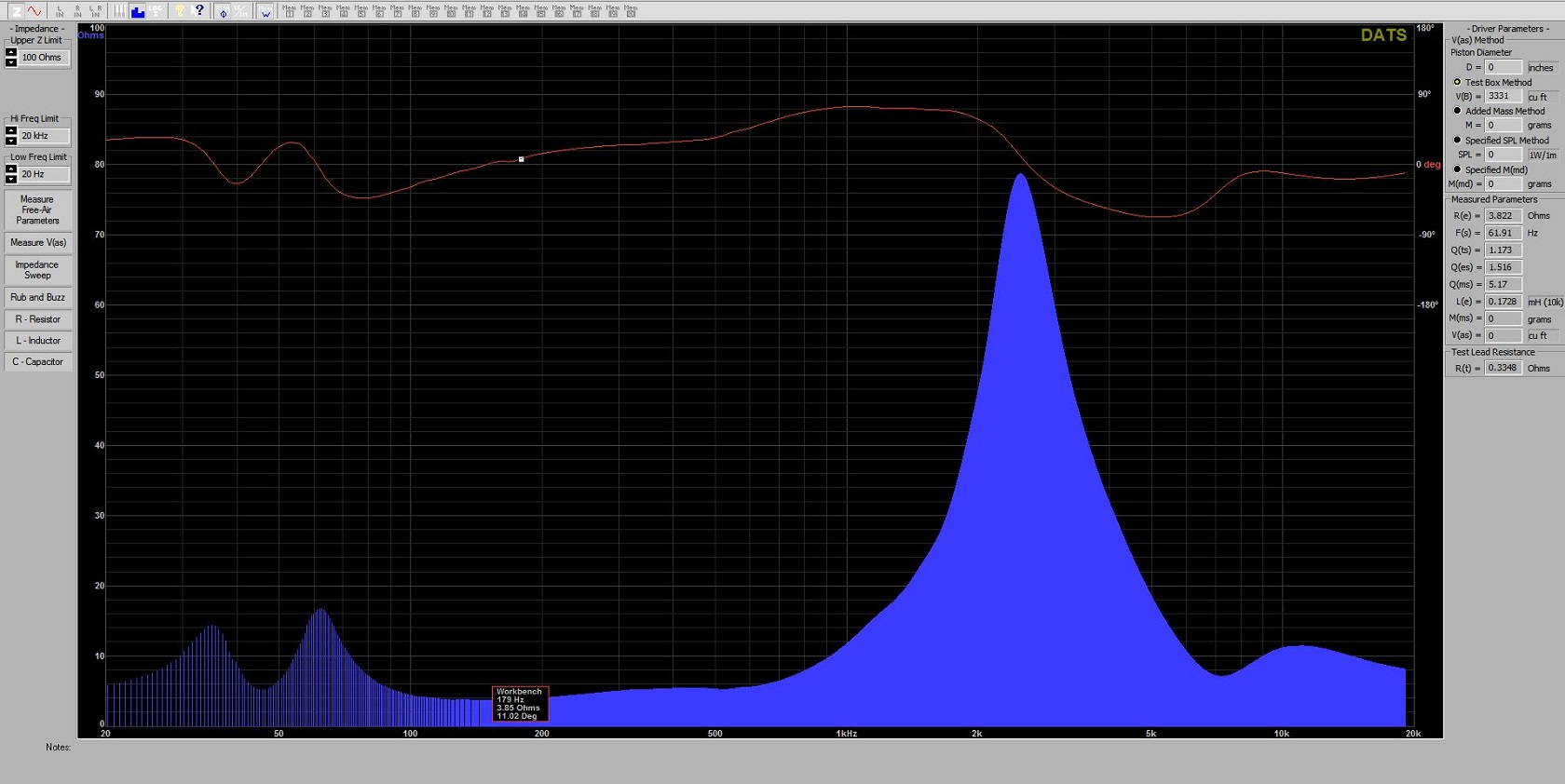
Here is one from a forte II same deal as above, new parts using stock schematic and values.

-
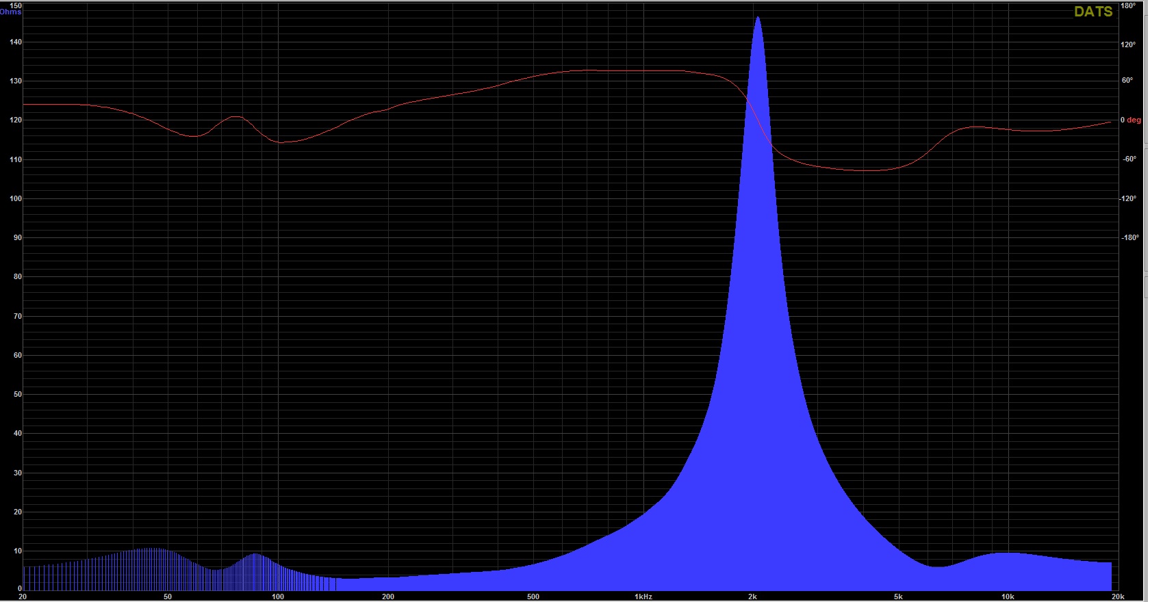
Would like to learn some of the basics in reading the data of a impedance plot like this one to consider improving on a xover. This one is from a T5000 with updated parts still using the stock schematic values.
-
How to capture DATS screen for posting
Alexander replied to Alexander's topic in Technical/Restorations
Thanks gents, WMcD - embarrassed that I had not thought of that The Snipping Tool is perfect. Thanks everyone again. -
Want to be able capture the screen image(s) on the DATS program being used to plot the impedance curves of a few Klipsch speakers so they could be posted here for review. The format DATS saves them to is not recognized by any of the current software on my Win7 PC , any help on this?
-
effect of 2.5mh vs 3mh inductor on same load?
Alexander replied to Alexander's topic in Technical/Restorations
Got to finish up one speaker. Geoff, the motor board was like you found on yours. It looked like the brace blocks were doing the bulk of the work holding it in place. The seams were extremely narrow - say the thickness of a piece of paper but they were there none the less. Gorilla white glue was used, it is very runny so the cabinet was tilted letting gravity do the work. It did take longer this way but it is what was on hand. Tried hot glue but just could not do the job the way I wanted it to be done.
-
effect of 2.5mh vs 3mh inductor on same load?
Alexander replied to Alexander's topic in Technical/Restorations
Thank you Geoff for the kind words -
You will be just fine with that avr-x2300w, most damage to speakers is done by being under powered (clipping) than too much power. Just don't use anything less than 16 gauge wire for hook-ups & for long runs step up the gauge - 14 gauge has always been my minimum. Also avoid "CCW" copper clad wire too. My sig below has a few good sources for wire
-
effect of 2.5mh vs 3mh inductor on same load?
Alexander replied to Alexander's topic in Technical/Restorations
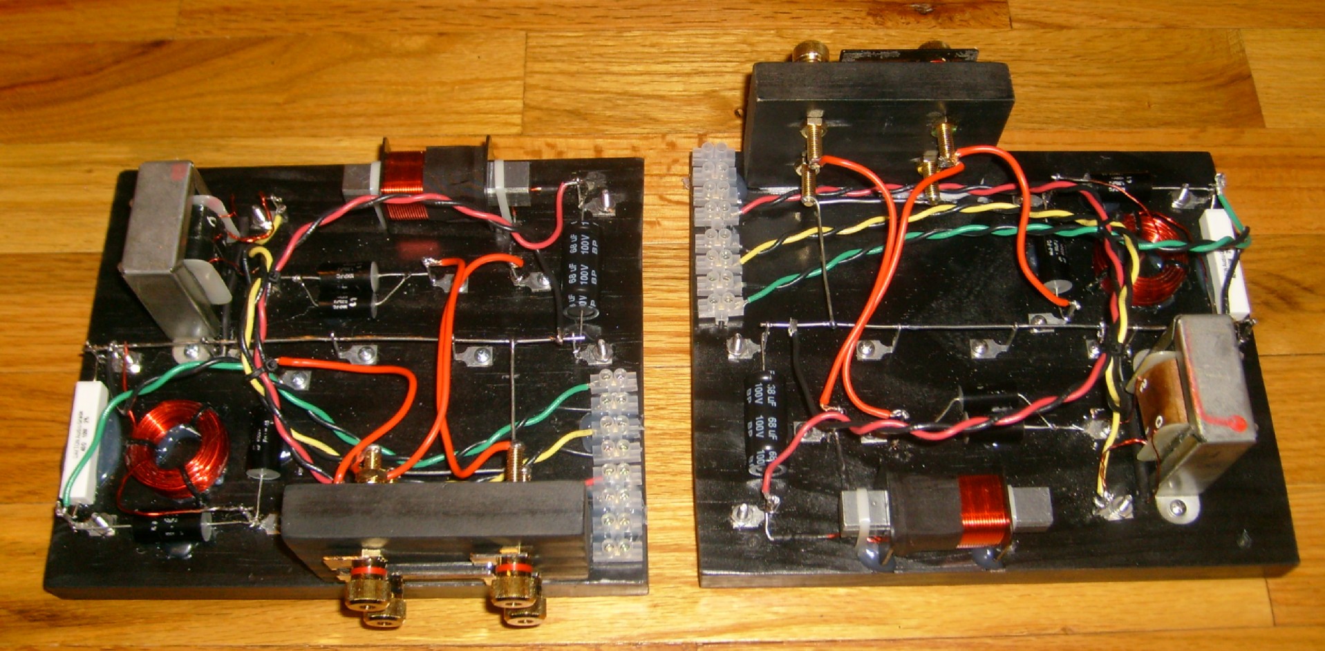
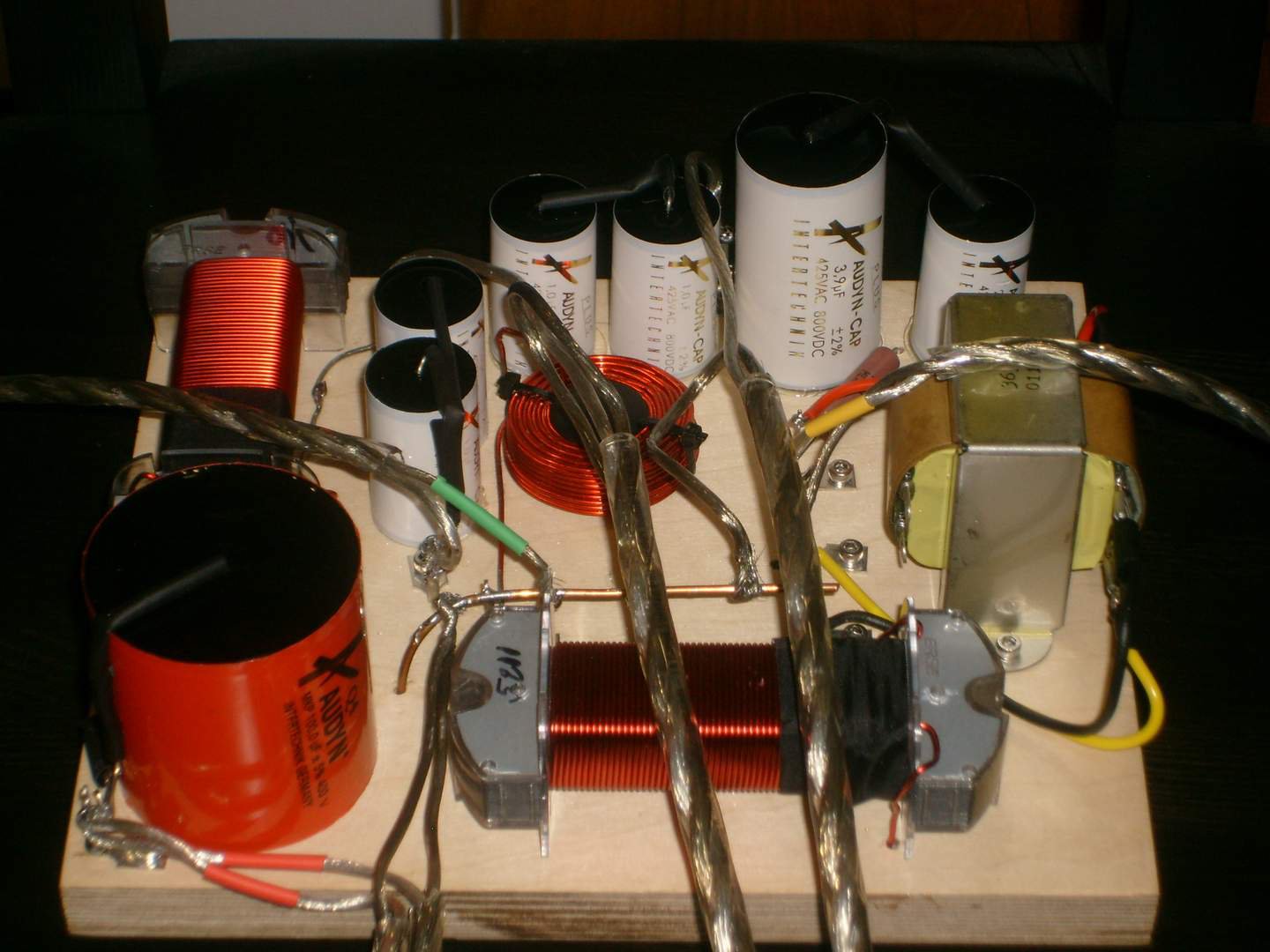
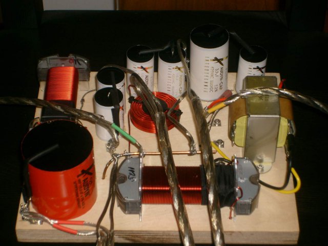
Here are the xovers finished, all hardware was either brass or stainless. Maybe we can have them mounted & wired before the end of this weekend.
-
effect of 2.5mh vs 3mh inductor on same load?
Alexander replied to Alexander's topic in Technical/Restorations
Geoff, I have the same xovers and the one missing screw as you have. Your woofer is a 4 ohm k28k, the replacement driver is also shared with the k23k & k25k of the Forte I/II family. I will put a light in the cabinets to look for "leaks" - hadn't thought of that . In stock form they sound very good and as you mentioned they are very similar to the Forte II's - a great speaker for less than Forte's if you can find them and do not mind the size. Looking forward to putting the upgraded xovers in and see how they sound, most of the original components were off spec by well over 10% -
effect of 2.5mh vs 3mh inductor on same load?
Alexander replied to Alexander's topic in Technical/Restorations
thank you for the links -
effect of 2.5mh vs 3mh inductor on same load?
Alexander replied to Alexander's topic in Technical/Restorations
Any one(s) that you might point me to that is better and/or easier than others? -
effect of 2.5mh vs 3mh inductor on same load?
Alexander replied to Alexander's topic in Technical/Restorations
I agree, the T-5000's are a sleeper value wise - they have the same drivers as the Forte I but in a bigger box. May try building a set of Forte I xo's to see how they sound. Curious if you have gone into your enclosures yet? Compared to the inside of my Forte II's they look to share all the same reinforcements & wood thickness.- 31 replies
-
- 1
-

-
- tangent 5000
- t-4000
- (and 2 more)
-
effect of 2.5mh vs 3mh inductor on same load?
Alexander replied to Alexander's topic in Technical/Restorations
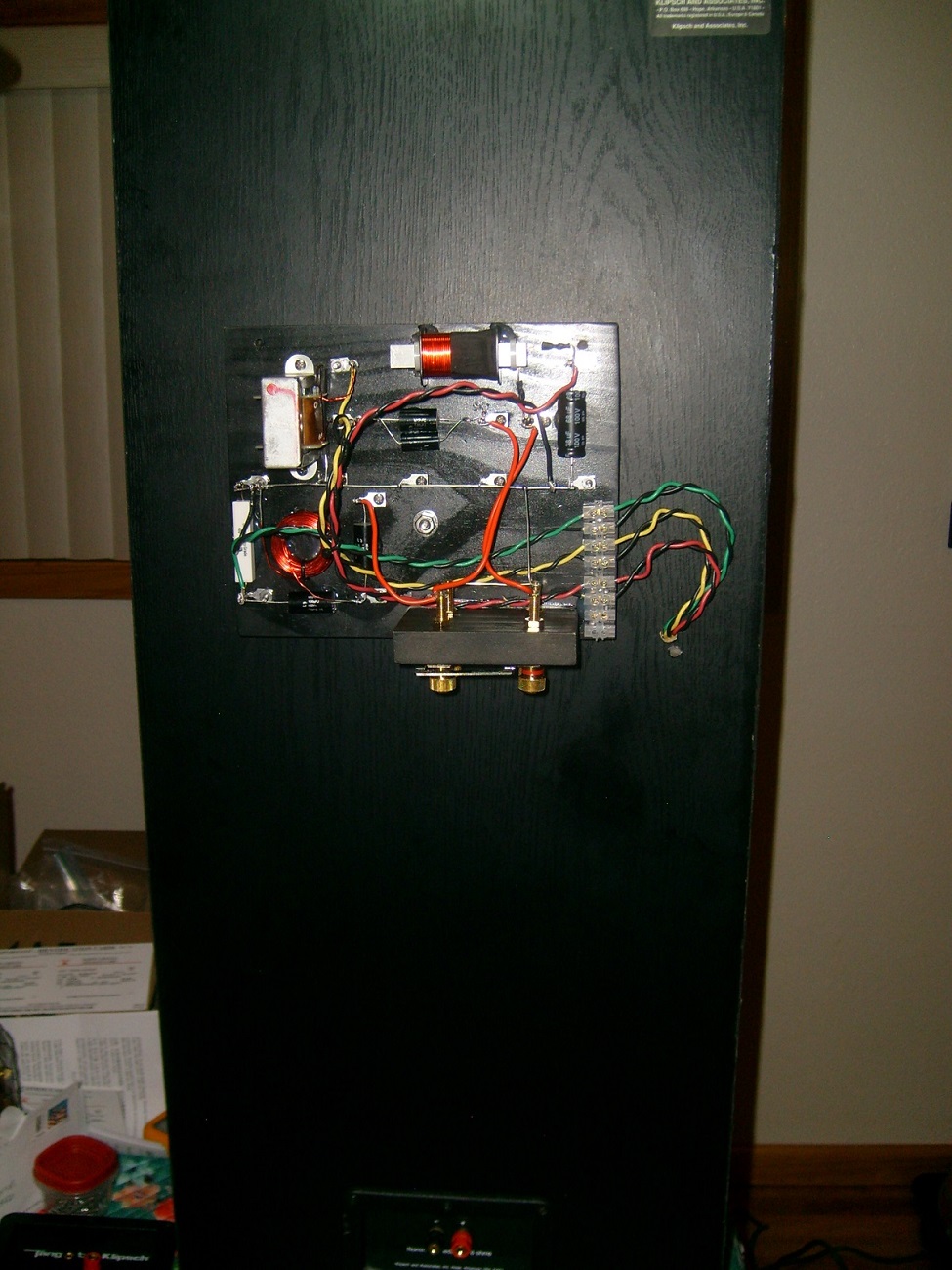
I should add that the plan is to hang these xo's on the outside back of the enclosures so changes could be done easier hence the binding posts. -
effect of 2.5mh vs 3mh inductor on same load?
Alexander replied to Alexander's topic in Technical/Restorations
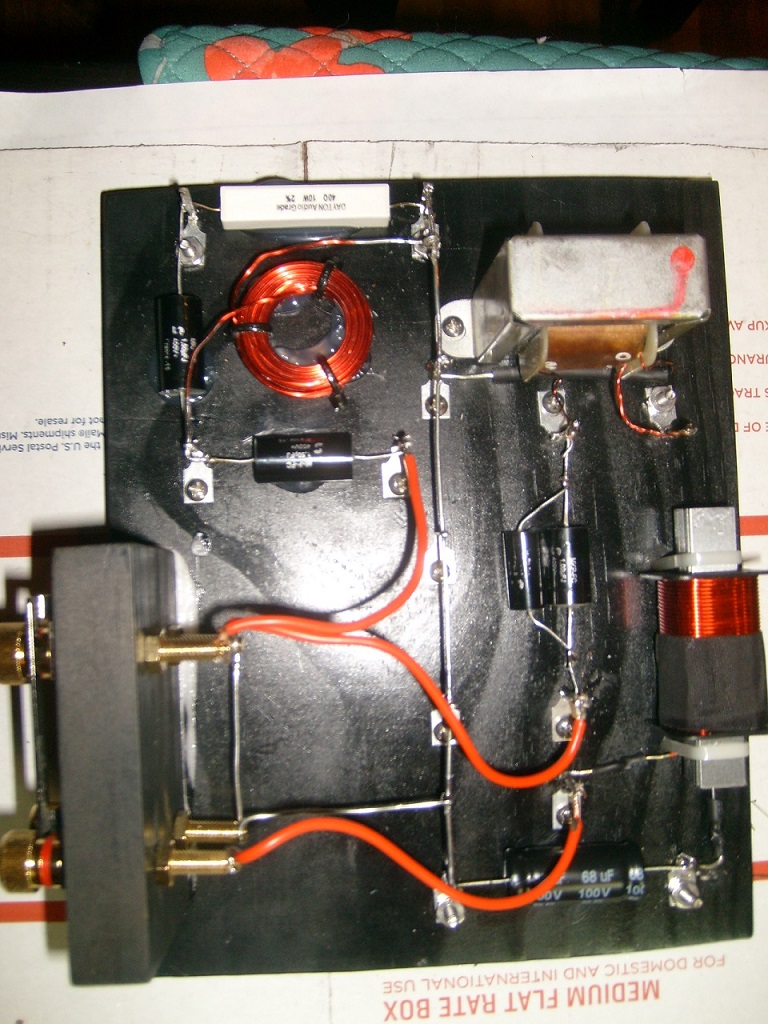
Been busy of late but finally got back on task. Finish building one xo off of the schematic, wanted to have it look real nice but too many goof ups and cruddy soldiering killed that. But none the less it will be functional. Did add a resistor at the tweeter and wired for bi-amp should the desire struck. Will be building the second one and maybe we can have a better looking version.
- 31 replies
-
- 1
-
-
- tangent 5000
- t-4000
- (and 2 more)
-
Fantastic! Been looking for this for a few months. Thank You
-
When measuring the lf inductors on my Klipsch OEM x overs I get 2.11mh & 2.17mh. I am curious what some of you would interpret these values to to be - 2.0mh or 2.25mh or? I can not find a valid schematic for these Tangent 5000 x overs so I have to "guess a mate" what their original intended values. As been posted else were we have a 68uf, 1.25uf for mid and 1.5uf x 2/.016mh for hf. The autotransformer's have zero markings on them btw.
-
f3 crossover Synergy F3's with damaged crossovers
Alexander replied to NightHawkATL's topic in Technical/Restorations
deang should be able to supply the schematic if he had built yours and no longer building for others, then one would be able to build a new set of x-overs from scratch if needed -
T-5000/4000 schematic shows : 2.5mh + 47uf, 1.0uf & 2 x 1.5uf + .16uf Markings & or actual measurements : 2.04 & 2.15mh + (68uf) 72.4/76.8uf , (1.25uf) 1.23/1.28uf, typical HF values Drivers are k75k, k53k, k23k & kd13k (passive radiator) (Tangent 5000 & Forte I use same drivers) no markings of any kind on the autotransformer's other than typical 0, 1 & 2 - will re-use Will be building an all new x over from scratch and my gut tells me to just follow what was actually on the original boards just tighten up specs, curious as some of you might consider anything different.
-
re-visited - posted schematic vs on board value
Alexander replied to Alexander's topic in Technical/Restorations
Finally actually pulled the x-overs out and am finding there are 68uf compared to the 47uf listed along with the 1.25uf in place of 1.0uf list originally in the schematic. These are still OEM BTW. Haven't checked large inductor yet to see if it is also different. -
effect of 2.5mh vs 3mh inductor on same load?
Alexander replied to Alexander's topic in Technical/Restorations
Thanks WMcD for your reply, the reason for my question is that I will be building a new OEM/Crites style x over for my t-5000's but if I were to want to try and sell them at some point down the road there would be virtually no market. On the other hand if I were to build Forte I x overs I would have a better chance of turning them. Hench the comparison of the two x overs as to how similar they are to each other. -
Looking at both the Forte I and T-5000's I see that they both share both the K-75 & K-53 drivers. Also the Forte I k-23 and T-5000 k-28 share the same replacement driver. So this brings me to the point that the two speakers other than the difference in cabinet volume they are essentially the same. So here is the question, the two schematics are the same other than the Forte I a 40 ohm resister and 3mh inductor and the T-5000 has no resistor and a 2.5mh inductor. I understand the resistor but what is the actual difference created with the two different inductor values?
-
Someone asked what gauge wire was used, the input wires from the terminal cup posts is 14ga and all the stock 18ga driver wires was upped to 16ga
-
Not a stupid question, that is how we all learn. You will need to measure any component out of circuit.
-
Are you measuring the caps in circuit?