Neandertal
-
Posts
54 -
Joined
-
Last visited
Content Type
Forums
Events
Gallery
Everything posted by Neandertal
-
Need help in finding hardware for a build project
Neandertal replied to Neandertal's topic in Technical/Restorations
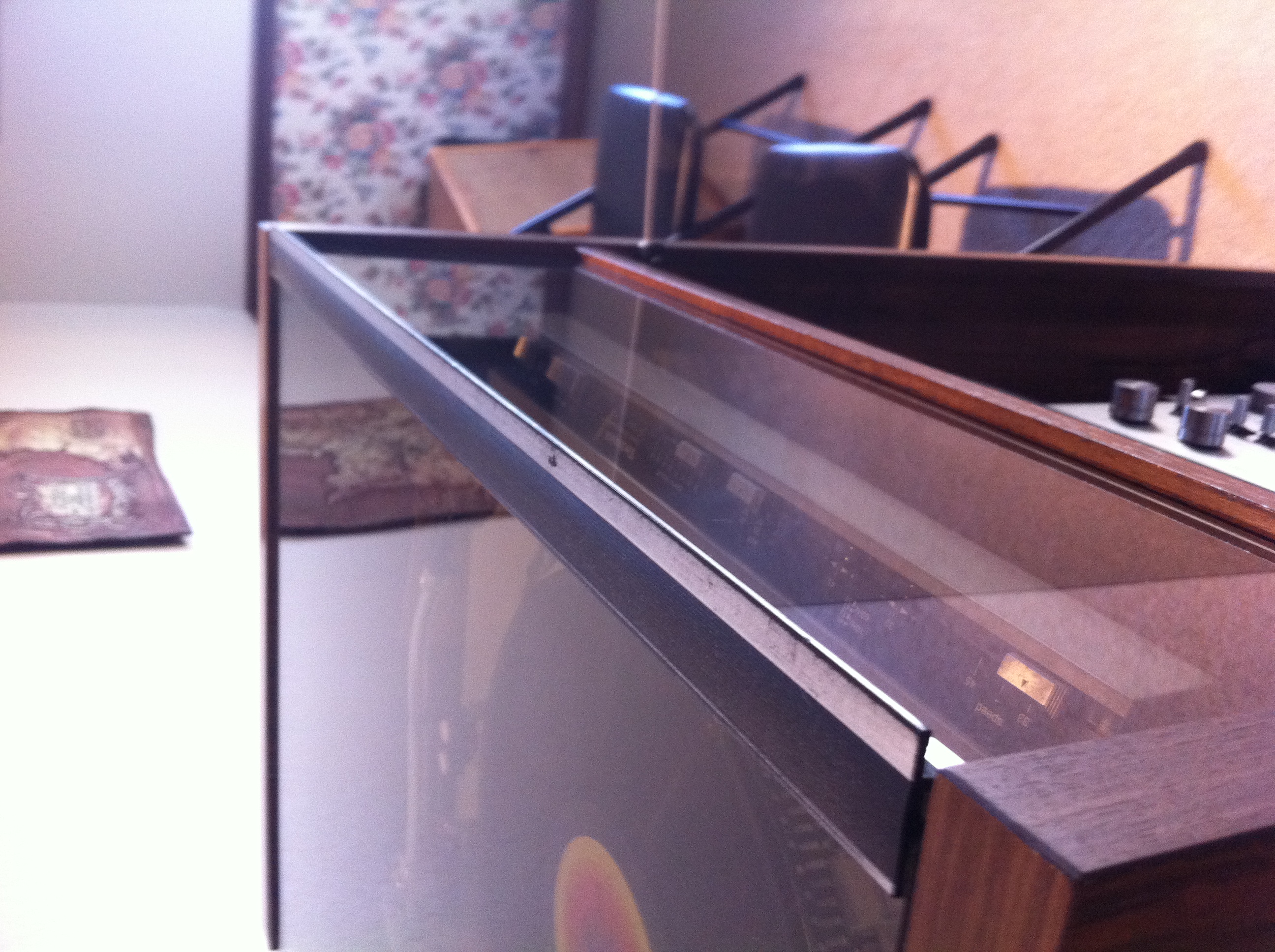
Last photo:....... Thanks folks,
-
Need help in finding hardware for a build project
Neandertal replied to Neandertal's topic in Technical/Restorations
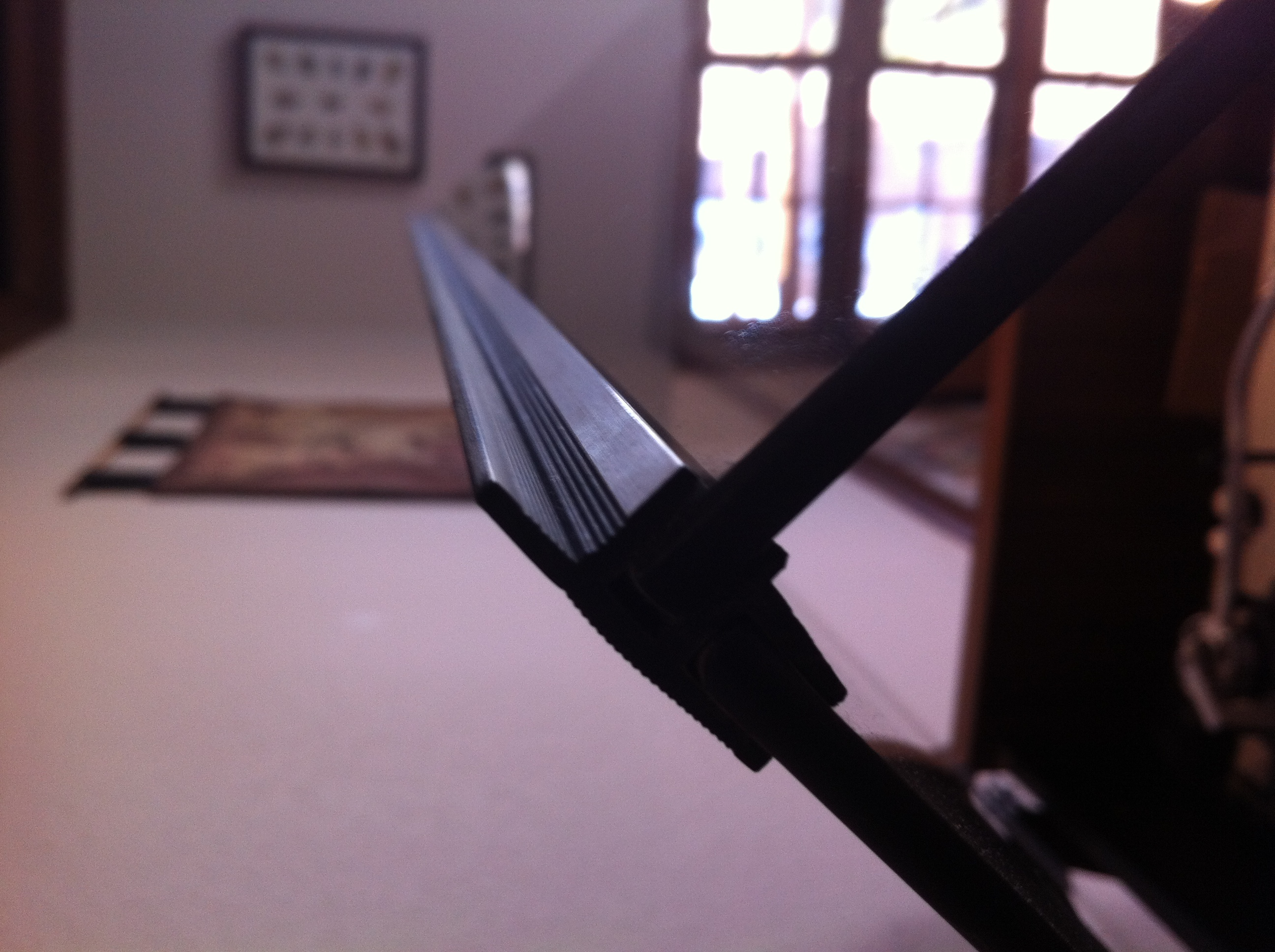
Front frame/lift edge:
-
Need help in finding hardware for a build project
Neandertal replied to Neandertal's topic in Technical/Restorations
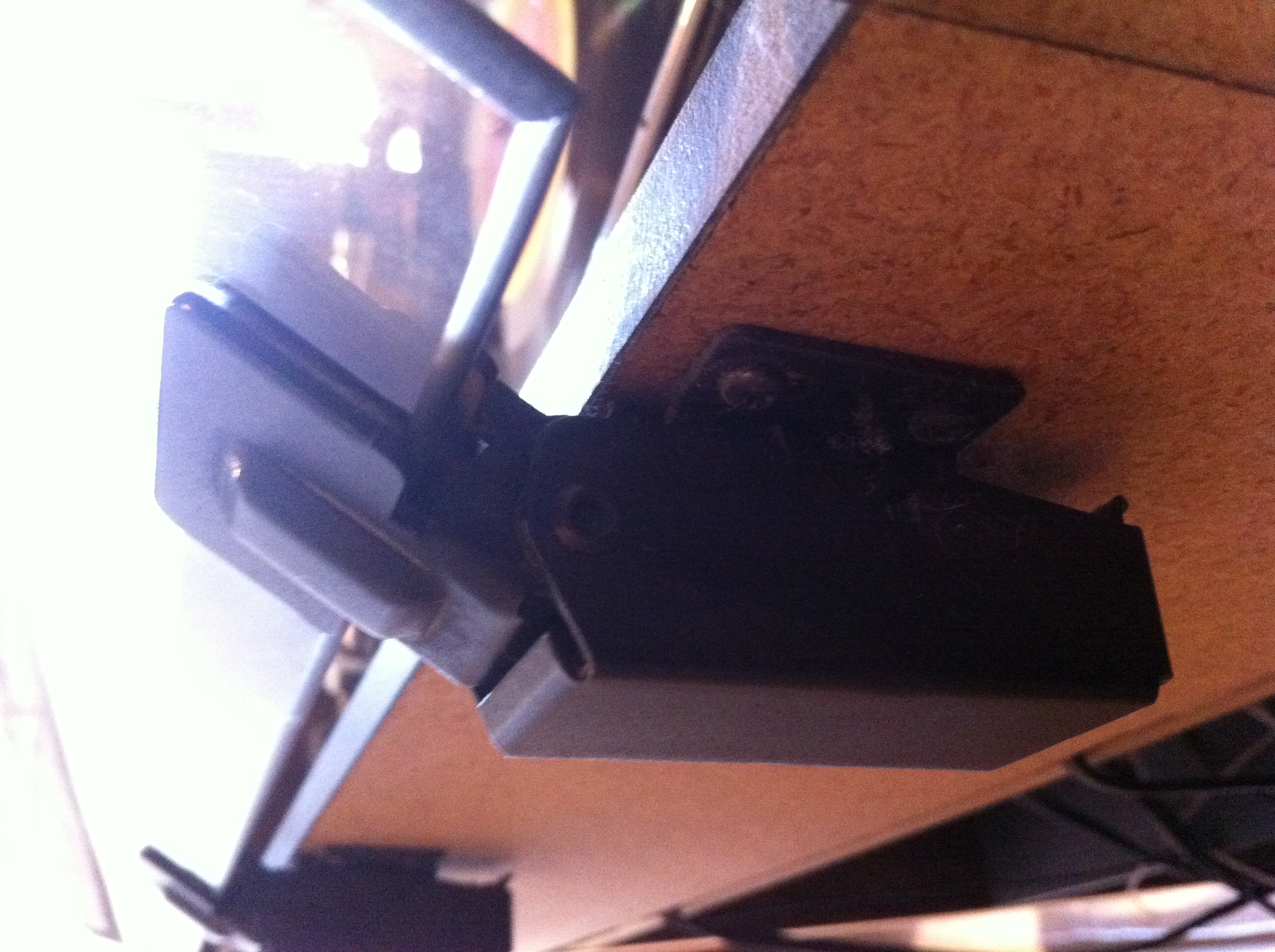
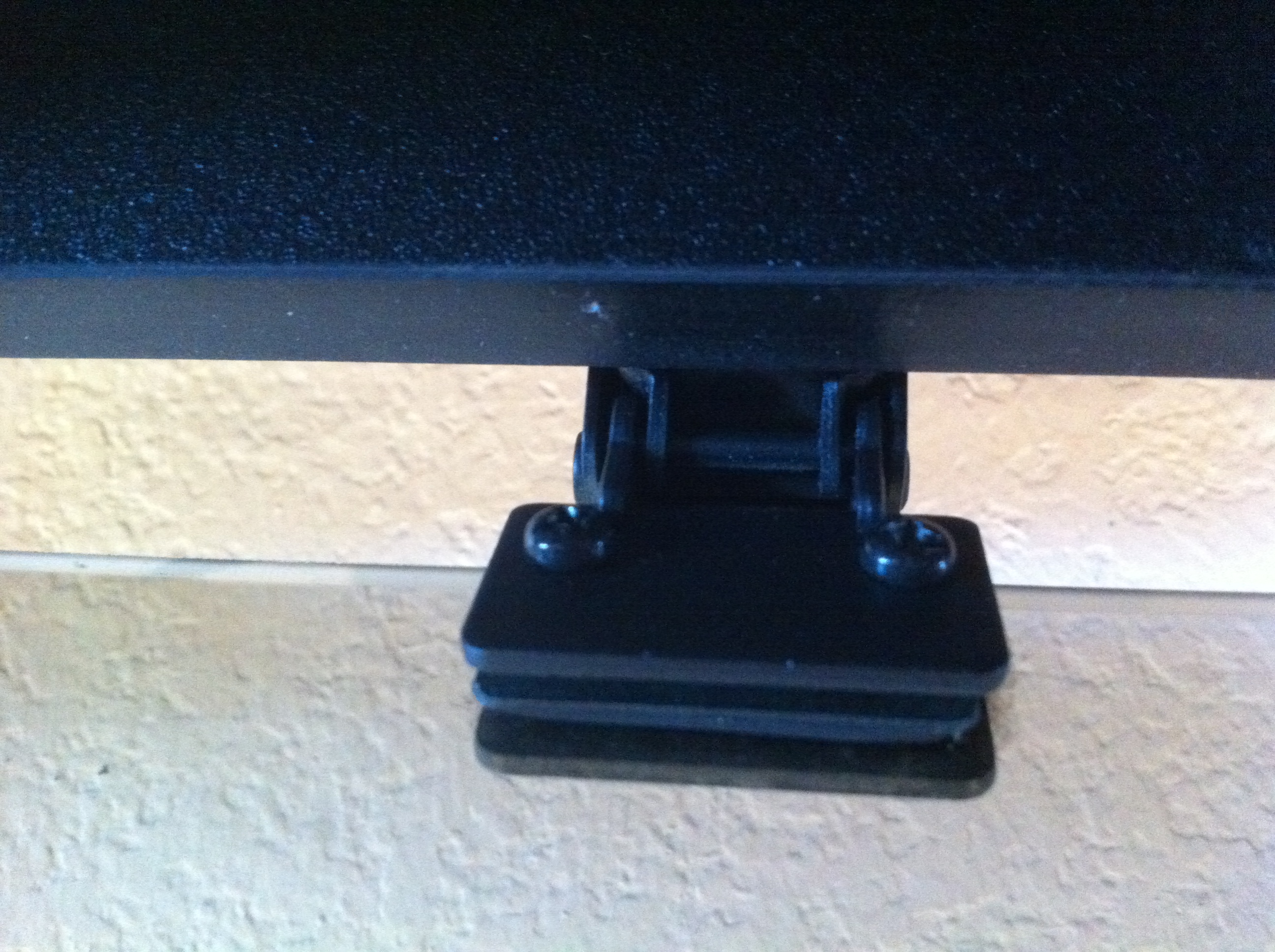
hinges again:
-
Need help in finding hardware for a build project
Neandertal replied to Neandertal's topic in Technical/Restorations
Hinges
-
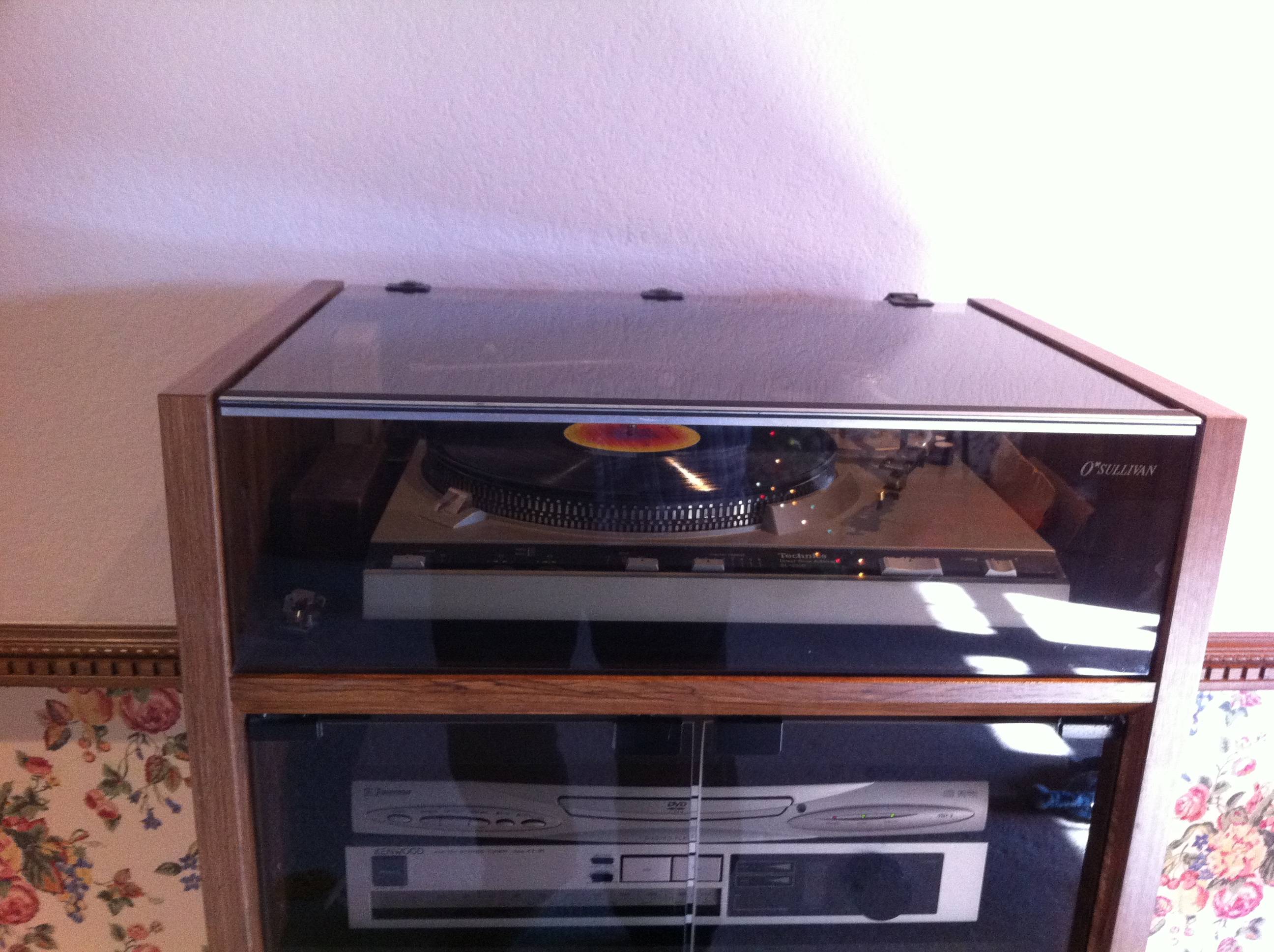
Hello folks, I am looking to re-build/re-work my old stereo cabinet for my new theater room. I have an old O'sullivan AR-177 stereo cabinet that has served me well for over 25 years. I now wish to rebuild it as a lower, double wide unit for my current hardware. What I am needing is more of the spring loaded, rear, glass top hinges. I have three from my current unit but am looking for 3 to 5 additional hinges for my new design.............................. .................................................................................................................... I also hope to find a supplier for the glass cover lift edge. That is the 90 degree frame piece which allows the glass top and glass front to form an enclosure for the top located turntable and/or the tube amp. I have posted pictures of what I am looking for at: ................................. .................................................................................................................. neandertal.imgur.com (May yet be able to post them here if I can figure it out.) ................................ ................................................................................................................... If I can not match these exact pieces, does anyone know of a source that can provide similar functioning units? I am intending to build a cabinet which is "double" wide and will allow me an opening turntable top on one side and an opening cover for the tube amp on the other side. Any help to guide me to these pieces would be greatly appreciated. ................................................................................................ I am finally able to build my long desired theater room and I am planning to build a new hardware cabinet with the veneer matching my speakers. Will take several months of work and I would be happy to share the progress if any are interested......................................... Thanks, Bert
-
Where is the thread on reverse-engineered Jubilee??
Neandertal replied to bhendrix's topic in Technical/Restorations
Also, I need to add I do not know who did the PDF drawings. I work in AutoCad and the drawings I posted were as jpgs. The first ones inserted in this thread are the ones I drew. I also would appreciate a zip of all the data that has been collected for the Jubilee in case I have missed something. Bert -
Where is the thread on reverse-engineered Jubilee??
Neandertal replied to bhendrix's topic in Technical/Restorations
Hello, I am "neandertal" and the drawings for the Jubilee are mine. I was working on reverse engineering the best match to Paul's dream of the "best" possible Klipsch speaker. I used the input from all members who had any exposure to the Jubilee prototypes or any possible suggestions. I (we) produced the design drawings from a composite of ideas. The well dried up and no further suggestions resulted in the project dying before we completed the whole package. The base bin was fairly well resolved but we never did come up with a hardware list or any cross-over ideas. I will have a set built by the end of the year to prove-up all the assumptions made in the design process. I will be glad to continue work on a final set of drawings if we find a renewed interest. Bert -
Jubilee - D.I.Y. drawing project (work in progress)
Neandertal replied to Neandertal's topic in 2-Channel Home Audio
Hello again folks, I hope we are not yet finished with this effort. No response, ideas, or input for a few days. Have we hit a brick wall or are you folks doing "detailed research" and will provide outstanding data for us to bask in? Anyone close to Hope, Arkansas that could visit Mrs. PKW and research (spy) on the Jubille? Trey.....any offer of helping us? Any "formal" response at all from Klipsch Audio Technologies? Trey...does Klipsch WANT to sell the LF bin to the general public in any volume? Anyone want to discuss the driver hardware? Network ideas? I will produce drawings of the board cuts (including angles) after it becomes obvious that no changes will be made to the "final" design. Bert -
Jubilee - D.I.Y. drawing project (work in progress)
Neandertal replied to Neandertal's topic in 2-Channel Home Audio
Hello again, Gil...I patent searched the following names and words: Klipsch Klipsch, Associates Delgado (co-author on the Jubilee paper, Delgado was noted in patent #5,000,286; "Modular Loundpseaker Design") Hope, Arkansas and a few others If the Jubilee is patented in any form it would not have been by PKW, Delgado, Klipsch and Associates, Klipsch Audio Technologies, or any combo of the Klipsch name. Bert -
Jubilee - D.I.Y. drawing project (work in progress)
Neandertal replied to Neandertal's topic in 2-Channel Home Audio
Here is the motor board in it's most simple form. No drone and the drivers centered. Easy and well balanced but does cut the A-B throat distance to a value less than that of the reference numbers. Bert
-
Jubilee - D.I.Y. drawing project (work in progress)
Neandertal replied to Neandertal's topic in 2-Channel Home Audio
Here is the motor board with a 12" drone. This is a work in progress. I still do not have a good idea of what the drone is doing. Need your imput folks. Bert
-
Jubilee - D.I.Y. drawing project (work in progress)
Neandertal replied to Neandertal's topic in 2-Channel Home Audio
Current (April 4) plan veiw of the LF bin. This is the design using the 5"x9" driver slots in the motor board. Does this look like what you folks believe it should appear? Bert
-
Jubilee - D.I.Y. drawing project (work in progress)
Neandertal replied to Neandertal's topic in 2-Channel Home Audio
An open answer as to what I am trying to achieve with this design effort. A few points are: 1) Attached is a drawing of what I believe may be the greatest benefit of an avaliable Jubilee for the unwashed masses. The beast need not be perfectly fit into a 4' deeep corner to work. The attached drawing shows how if would be easier to use than a Khorn for the same (better?) sound. Khorn quality sound without the need for corners....i'm interested. 2) I would like to generate a set of plans for THE speaker Paul was interested enough in to spend his retirement days designing. This would be the 2-way design with a drone in the LF bin. 3) A 2-way design without the drone in the LF bin This would be the bin currntly available from Klipsch but we would also have the data of the HF horn and 2 way crossover. 4) A 3-way design with or without the drone in the LF bin. I have a personal interest in a 3-way design using the best LF bin design we can come up with and the squawker/tweeter upper combo from a Heresy to top it out (the Jubilee bin would allow a 700hz crossover and hence a K-700 horn from the Heresy). This would give me Khorn that I could use on the wall in which I lack the proper corner for a Khorn and have a best tone match with my Heresy surround speakers in a 5.1 setup. Maybe not a purest intent...but one which best matches may current needs. 5) Any other combo any of you may have a need for. P.S. Anyone inform as to how I may place a drawing in the text? Thanks, Bert
-
Jubilee - D.I.Y. drawing project (work in progress)
Neandertal replied to Neandertal's topic in 2-Channel Home Audio
Hello again, I have been working on the drawings this weekend and have several updates that will follow. I would first like to address Trey's comments. 1) This effort is for D.I.Y. usage. I have no intend to build and sell any speakers. I also do not have any interest in is selling a drawing set (this is a group effort in an open forum). This project is to educate ourselves in what may be the best home sized speaker Paul Klipsch ever designed. Since it has been made very clear that Klipsch Inc. will not build them....let us who have the some skill and time try to best honor the man and the design which Paul worked on as his last/best effort. He had a need to design it....some of us have a need to hear it. 2) I have searched and do not find a patent on the "Jubilee" design. I checked back to 1978 and find only 4 patents awarded to Paul between 1978 and his death: #4,138,594 The LB-78 speaker (Little Bastard) #4,210,223 Low-freguancy folded horn (Looks to be the commercial KPT-MWM prototype) #4,237,340 Crossover network for the "Little Bastard" #4,387,786 Anechoic Chamber Arrangement 3) I am aware Klipsch is selling the commercial LF bin from the Jubilee. What we would like to see is the design that does include the drone (for home use) as may be considered to be the "ultimate" Klipsch speaker. Also need to see if we can develope the two-way design by determining the HF horn design and network details. Maybe we can help generate a sales market for the available LF bin if we could match it with the remainder of the Jubilee design for home use. 4) Trey...any offer of data from your end to support what is an attempt to promote the legacy of Paul Klipsch? As noted above....maybe we can help you sell a few more LF bins without cutting Klipsch out of sales of a speaker you admitt won't be sold. Bert -
Jubilee - D.I.Y. drawing project (work in progress)
Neandertal replied to Neandertal's topic in 2-Channel Home Audio
Hello again, I have read, I have thought, I have calculated. Here is how it MAY be with regard to the slot opening at point A. PKW's design data has the throat at .029 sq.m. The .pdf drawing measures the opening at 4.916" so lets bump it to an even 5" (the pdf drawing has been pretty darn accurate so far). The resulting half throat created by the splitter is 2.5" which is the same as the A-B flare width. This would also meet D-man's comments about having the slot opening match the following flare width. Also matches the concept of the splitter acting as a two sided reflector. With the Point A throat at .029 sq.m (for BOTH the upper and lower drivers combined...all the other measured throats have been combined numbers) which equals 44.95 sq.in. and a width of 5"....the height would be 8.99" or just about 9" if we are a touch sloppy when the slot is cut. So we now have a 5" by 9" slot split into two halves and doubled by having two drivers. Now to the A-B flare length. By making the slot wider....the length shortens because it is measured from the center of the bifricated(sp?) slot at point A. I now calculate this to be 7.436" or .189m horizontal. We are short from the PKW design of .209m. Now remember this is in the horizontal plane. Now follow into 3-D. With the assumed LF bin at 38" tall (PKW's number)...the interior motorboard is going to be 36.5" tall. Asigning 12" to the center drone, this leaves an upper and lower 12-1/4" for the drivers. Centering a 5"x9" slot in this area gives us a Point A which is 6-1/8" from the top and bottom of the motor board. Each driver's horn is at 18-1/4" wide (2x 18.25" = 36.5"). The CENTER of EACH horn is 9-1/8" from the top or bottom. The VERTICAL distance between the 1/2 slot A CENTER and the center path of an individual horn is 3". Now to geometry...the horizontal path is 7.436" and the vertical is 3"....the linear path is 8.018" or .204 m. This does compare well to PKW's design value of .209 m. I will draw this up if the majority agree this is a sound path to follow. Once the horn flare passes Point B the two individual half horns are full height in the body of the LF bin. These assumptions will have the A-B flare being built with asymetrical(sp?) wings. Still need to know if the drone opens in any shape or form into the horn path. Any quesses as to how that thing works? Anyone have a clue as to what drone is used? Will draw more soon. Keep feeding me ideas. Bert -
Jubilee - D.I.Y. drawing project (work in progress)
Neandertal replied to Neandertal's topic in 2-Channel Home Audio
D-man...thanks for looking and input. I hear what you say on the 10" vertical opening for the 12" driver. Unless someone else has a better idea I will assume that the 10" vertical component will be now accepted "standard". I will be making new drawings (I am sure many new drawings) when WE come up wth a better understanding of how the motor board looks. This is going to be interesting..... Bert -
Jubilee - D.I.Y. drawing project (work in progress)
Neandertal replied to Neandertal's topic in 2-Channel Home Audio
Here is the fun part...how to get two 12" speakers and a x" drone in the motor board. The atached drawing show the most "simple" way of placing two speakers only. This would be correct for a LaScalla type placement. Problem is... no drone. Also note that the point A to B distance is short compared to published values. If one makes room for the drone..the two drivers must move to the top and bottom of the housing. A-B path will distort but will become longer. The A point throat can become larger and better sized. Will draw up a three port idea when you folks help out with possible suggestions. Need to know.... How large is the drone? Does it have open air path to the main bass outlet path? (or does it open only into an area 2-1/2" wide as trapped by the flare pathes formed by the two drivers?) Also...where, what, why, when, how do we get info on what the drone is and how we may btain one? I would like to see some horizontal (along sound path) bracing between the doghouse and the inner "wall". I know that there are two braces between the inner and outer "walls" of the final outlet path. A single 3/4" plywood brace in the middle of the LF bin would be great if we knew what the drone was doing. Input and comments from you folks may yet allow us to see and hear a live Jubilee. I will do the drawings as per group input on this forum. Someone needs to track down hardware and x-over details. Bert
-
Jubilee - D.I.Y. drawing project (work in progress)
Neandertal replied to Neandertal's topic in 2-Channel Home Audio
O.K....here is where it gets fun. I have now adjusted, pulled, twisted, shrunk, expanded little bits of the pdf tracing to BEST match the publish data. I did have to assume some things to do this. Now we are at the point to make suggestions or corrections. I would like to list the points where assumptions had to be made: 1) Height of the LF bin: From the published data and the conversion from metric to english I have set the bin height at 38" exterior and 36.5" interior. The back volume is dead-on for these numbers. I believe this confirms the "doghouse" is correct in size and proportions. 2) Point A: A real guess here. Need height of trhroat opening and width (location may also be an issue and will talked about it in the motor board drawing). To keep the A-B distance as correct as possible, I need to keep the throat vertically narrow. Even as shown the lenght is slightly short. The shown area for A is correct only if one assumes both throats togther, both sides (halves) together, and a 6" tall opening. I do not like these assumptions (and yes, I do know what happens when you assume something). We need a wider throat but this kills the A-B length unless the A-B path is not measured horizontal?...hummm?....hence motor board questions later. 3) A-B length is a little short (see above). 4) Point B: Point B is a dead-on match if one assumes that the measured point in an average of the entering path width and the leaving width. Since the A-B path is flared along the motor board face (as in the LaScalla), the beginning of the B-C path could and should be wider (no more vertical occuring flare). An assumption yes...but it calculates perfect and does follow the pdf tracing quide. 5) Point B reflector: I have the reflector sized at 2-1/2" as per the A-B path width to better match the previous postings that suggest that 45 degree reflectors should be full width. I agree with this engineering. If one overcomes the belief that the corner is now contricted by the larger reflector, it should work much better. Need to remember that the sound waves are pressure waves reflected by the angle and not waterlike flow through the corner. Not restricted but reflected. 6) Point C: No real problems here....followed the pdf tracing and adjusted a few millimeters here or there to make the numbers match. 7) Point D: Numbers end up real close. Total length will be a better match if the A_B distance can be extended. All calculations have been measured in the CAD program at the shown micro measurements. I have then made the adjustments to carpentry units measured at 1/16" accuracy. (As close as most of us really cut the projects we build.) These can be posted at 1/32" measurements if any should want them that accurate. Next... the real problems begin. Bert
-
Jubilee - D.I.Y. drawing project (work in progress)
Neandertal replied to Neandertal's topic in 2-Channel Home Audio
This is the same modified tracing of the J.A.E.S. drawing with throat paths measured for length and the A,B,C,& D evaluation points calculated. This was done to compare how the .pdf drawing matched the engineered values provided. To be considered in this evaluation was: 1) How accurate the original drawing was for the published paper and: 2) How much distortion had been introduced in transfer to the article formating, publication, .pdf scanning, ect... I admitt I was surprised at how well the tracing matched the published numbers with no adjustments beyond those previously mentioned. Any forum member who know how to directly post these drawings into the body of this thread are asked to do so. I do not know how and personally hate to have to open the attachments and then try to read the subject text. Bert
-
Hello, I have decided to invest time and thought in producing an engineered set of Jubilee drawings. My hope is to reverse engineer a design which matches the original designed by PWK and that can be built by us "handy" types. The attached file is my best attempt to reproduce the Jubilee as found in the .pdf files previously posted on this site. Using the J.A.E.S. document imported into AutoCad I traced the .pdf print. I "best" interpreted the slightly distorted lines, made all intersections square where appropriate, set all boards at exactly 3/4" thick, ect.... The intent was to best be able to see what the J.A.E.S. drawing had to offer. The drawing was then scaled to match the .540m front width as stated in the body of the article. I hope to dirive from the fellow members of this forum help and suggestions to allow us to come up with enough data to generate a set of plans that will allow us to build the Jubille. The following drawings are a work in progess. Thanks, Bert
-
could I make "mini lascalas" using 10" drivers?
Neandertal replied to Binkstir's topic in Technical/Restorations
Hello, Just for fun and a little mischief I built a 1/2 scale LeScalla. I posted the info and photos on on the forum (I believe it was the "modification" forum). You will lack the lower "bass" output with a smaller size but could and would have something useable. I would think that with your width limitation but no height problems that you could build at least a 75% to 80% sized LaScalla by distorting the base bin into a 16" by 24" profile with the 24" vertical (90 degree rotation from the norm). The low freq sound in not directional (or at least lesser so) and the rotation should not be a major problem. This idea would possibly allow you to up to a 12" driver. I am currently woking up a little project to try this basic idea out with an LB76 varient I am planning. This could be done with a 10" or 12" woofer. The mid and tweeter would be from a Heresy and I would would use a 10" or 12" "single" wedge bass horn. May also build it as two bass drivers with opposite looking bass horns and the mid & tweeter in the middle. This would be a "low" height and "long" profile speaker that would serve as an all horn center under a widescreen TV. Would give up some at lowest base but would horn load all the audio range of most center channel output in a 5.1 or higher theater system. Something to do in the shop to keep busy! Bert -
Hello, I would be glad to offer my services to engineer design a fully scaled set of drawings on AutoCad for the Jubilee. I have built many a speaker and I engineer design on AutoCad each and every day for a living. My limitation here is that I have never seen (much less touched or heard) the Jubilee so I would be totally dependant on forum members to feed me measurements and details. We could develope a full set of plans as per the Belle set recently developed on this forum. Once the design is finished, I could post the finals in .pdf, .dwg, .dxf and several other formats so any and all could refer to them. Let me know if you folks would want to go to the effort to "engineer" a build set. I personally am intersted in building a set if we could determine what will be the cabinet design and if we could generate a parts list for the speakers and crossover. Bert
-
Build a La Scala using Heresey components ?
Neandertal replied to Dan MacLean's topic in Technical/Restorations
Hello, Funny you should ask. Attached is a photo of just what you may have been thinking. I have details and additional photos in the "2-Channel Audio" section of this forum. Bert
-
Half scale La Scala built and tested
Neandertal replied to Neandertal's topic in 2-Channel Home Audio
A back view of the two spaekers.
-
Half scale La Scala built and tested
Neandertal replied to Neandertal's topic in 2-Channel Home Audio
A better view showing the relative size of the mini-scala with a Heresy II.