henry4841
-
Posts
2370 -
Joined
-
Last visited
Content Type
Forums
Events
Gallery
Everything posted by henry4841
-
I've seen plants inside a LaScala more than once in my time. I will assume after significant other had passed away and she was left with speakers.
-
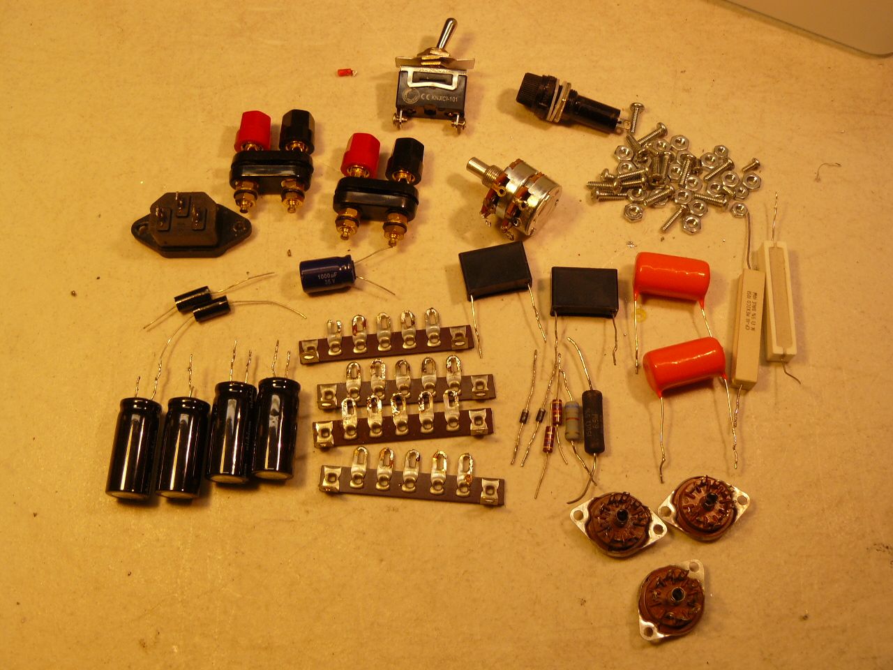
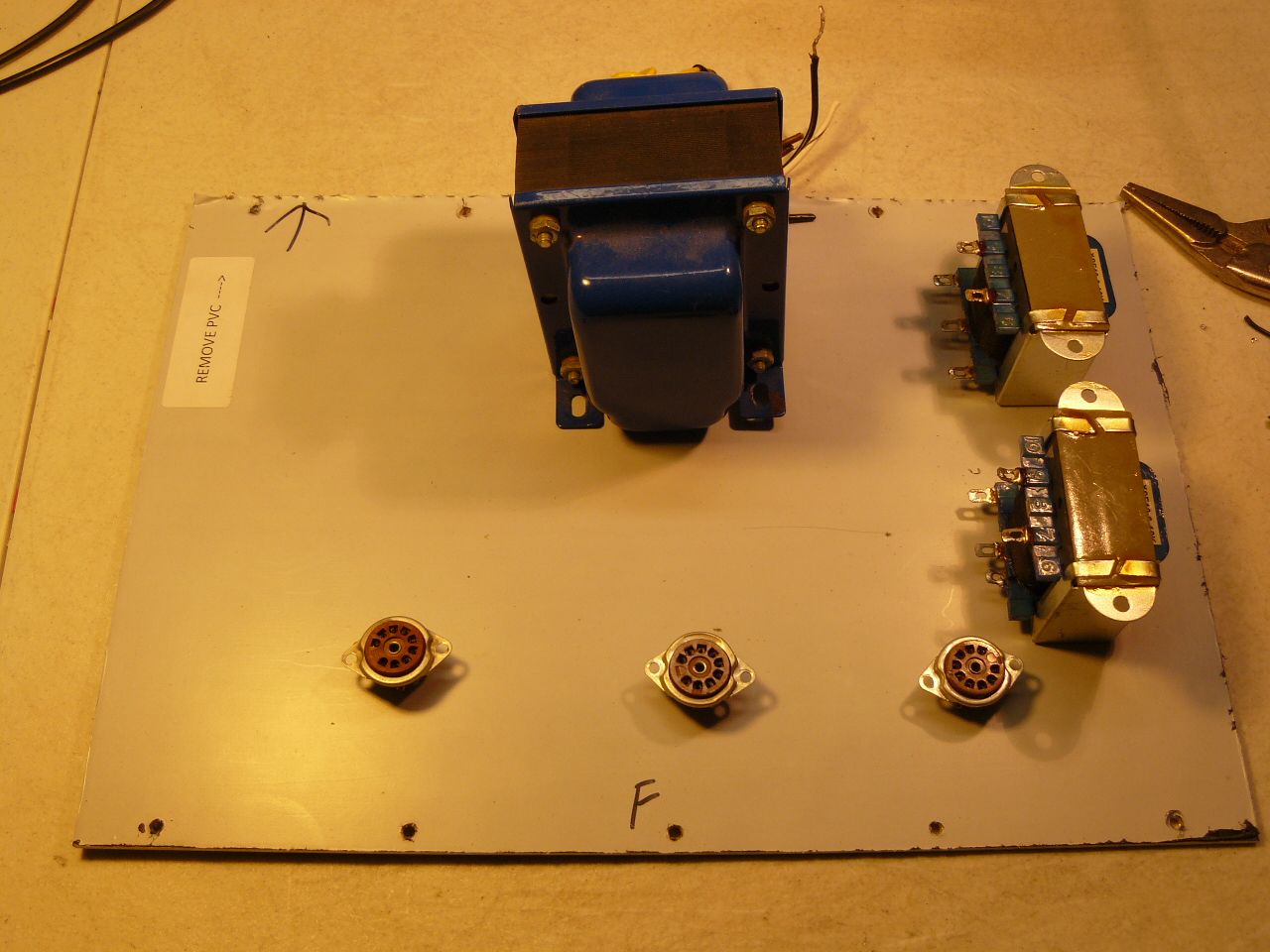
I have been busy with chores at 3 houses the last few days. I have a GF that lives on my street a few houses down that I have been seeing for 14 years. This year her single daughter moved on the very same street between her and myself so now I have 3 houses to take care of. I consider myself blessed to still be needed at 74 but it does take away from my shop time. Monday was installing ceiling fan in GF's daughter house, yesterday cutting grass at my house and GF's. This morning fixing leaking sink at GF's daughters house. But later this morning I did manage to sit down at my bench at start cleaning up the parts I am going to be using on this project. Not a glamorous job and time consuming but necessary. Also started layout of pieces on top plate. Of late I like to put all the AC lines, PS components and PS transformer on one side and the audio section on the other side keeping them apart as much as possible. For appearance sake though I am going to install the PS trans in the center of the amp with the wires going to the PS part. Being on top with the audio OPT's underneath will provide adequate distance to not be a problem.

-
Fevoman and myself PM regularly and I saw your setup. You are my kind of guy, I like what you have done. Excellent work.
-
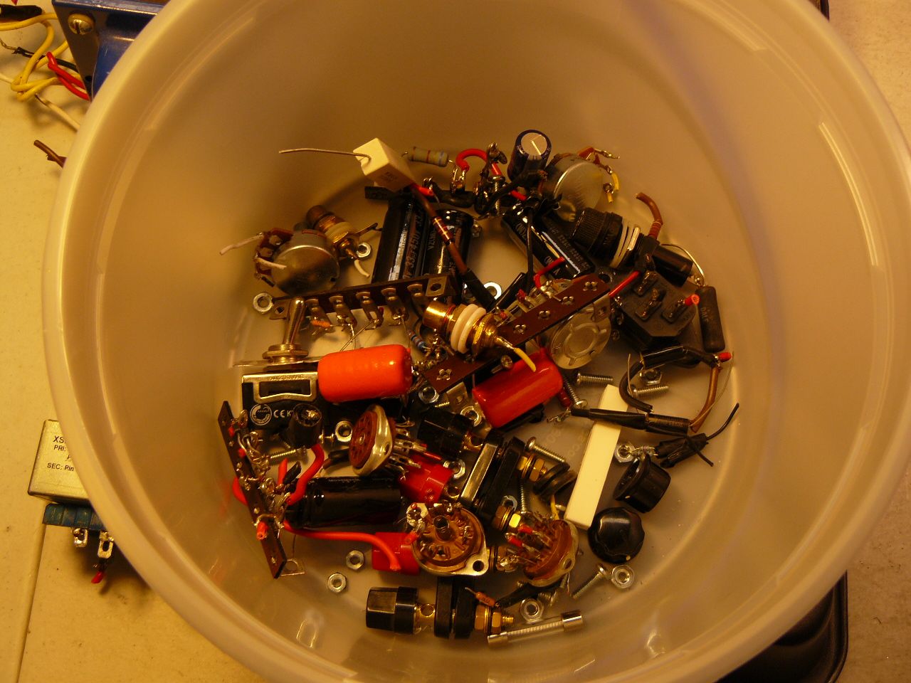
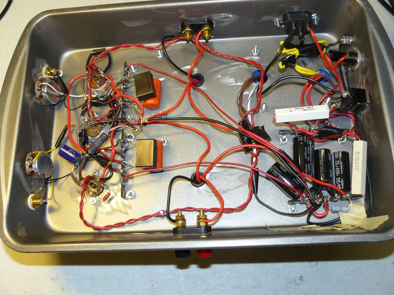
Old amp on cake pan taken apart. Another coat of linseed oil put on wood case this morning. I used Nichicon capacitors in the power supply so I will recycle them into the new build. I have so many working amps, last count I believe was 25 but I gave one to my son lately, that I am sure the caps have very few hours on them.
-
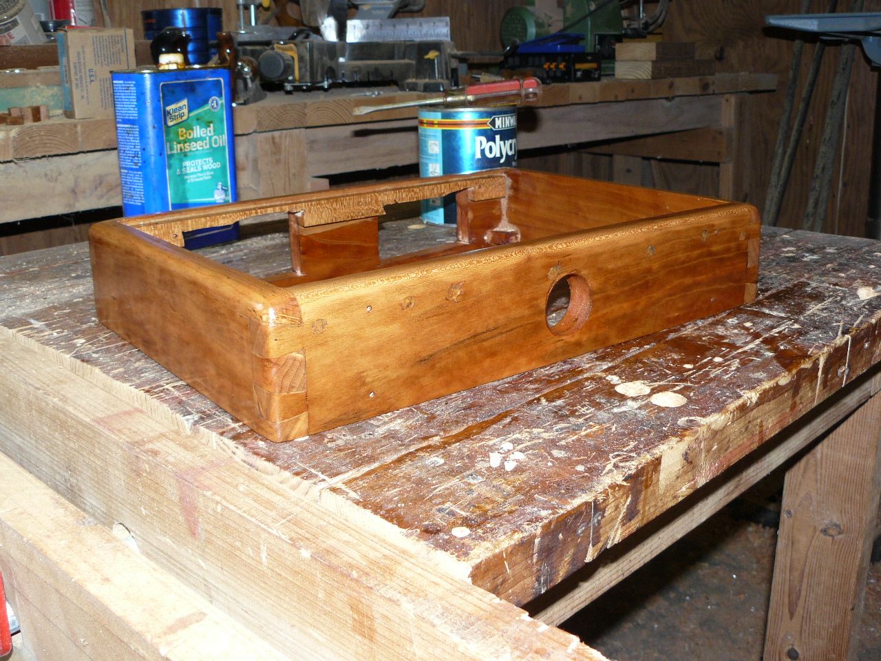
Wood part is almost done. All I need to do now is put on another coat or two of linseed oil to seal the wood and then I can start work on the aluminum sheets drilling holes and cutout for the IEC connector. Before I can do that though I need to take the cake pan amplifier apart.
-
Some more work on the chassis. One can avoid all what I am doing by purchasing from this guy on Ebay. I have thought about purchasing one myself instead of going to all the trouble I do making a wood chassis. But it does give me a reason to go in my wood workshop. Also is a link for the plate aluminum I have been of late. I really like this covered plate from this seller. https://www.ebay.com/itm/114550529401 https://www.ebay.com/itm/264760460739
-
Remarkable high frequency hearing.
-
I have a grandson that can hear a dog whistle. No one else in the family can. He cringes when he hears it.
-
Works fine for those on a budget but still want to learn and build and do not want all the components sliding around on a bread board. A bread board build is the term used by techs when testing a new circuit before committing to building in a proper case on just a piece of board. I made a number of amps and line stages on cake pans when I retired wanting to hear what an amplifier sounds like and not sure if I wanted to keep it.
-
Payed for more watts than needed for sure but in this original poster's case he already had the extremely high end Pass Labs amplifier before purchasing speakers. I expect anyone with good enough hearing can hear something with ear to speaker. I have amps and like Shakey and cannot hear a thing but that does not mean others might. Guy at Pass Labs gave the best answer to the question. I would not give it any thought myself if one cannot hear anything, or practically nothing, a few feet away. It only annoys me when you can hear noise on a quite passage from my listening position. It may well be the OP has excellent hearing and others may not hear a thing. An old mechanic gave me a good answer when I was complaining to him about a rear end noise on a car. After he heard it he just said turn the radio louder and it will go away.
-
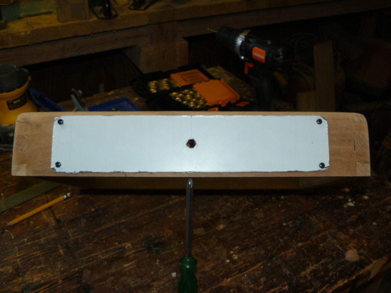
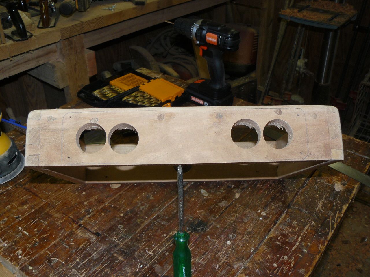
I dried fit and drilled holes for the front and back plates this morning. It pays to be careful of layout before one starts drilling. Then I drilled a hole big enough for the volume pot that is going to attach to the front plate in the wood chassis. Also drilled big holes in the wood for the accessories needed on the back plate components. I will cut out the rest needing removing with my jigsaw on another day. All for today. I am happy the way the front of the amplifier is going to look. The two holes inadvertently punched in the front now appear to be just a fault in the wood itself. I did have to alter what I usually do on the back panel to one long sheet instead of two seperate 3" X 3" plates to cover the holes mistakenly punched through the wood.
-
That amp should not hiss with our speakers. That is a monster amp and I understand the reluctance of shipping it these days having gorillas handling it. The inputs do need to be shorted for testing to see if hiss is internal or just picking up hiss on the input. Something like these work. Pass will want to know if and when you ever talk to them. https://www.amazon.com/VANTRONIK-shorting-Terminators-Reducing-Insulation/dp/B0833S6X1B/ref=asc_df_B0833S6X1B/?tag=hyprod-20&linkCode=df0&hvadid=459618435588&hvpos=&hvnetw=g&hvrand=8605458350157429580&hvpone=&hvptwo=&hvqmt=&hvdev=c&hvdvcmdl=&hvlocint=&hvlocphy=9052440&hvtargid=pla-942094768696&psc=1
-
Short the inputs on the power amp and see if you still have the hiss. If so it is your amp. Passlabs has one of the best warranties and customer support as any company I know. If the hiss is present with inputs shorted I would give PassLabs a call.
-
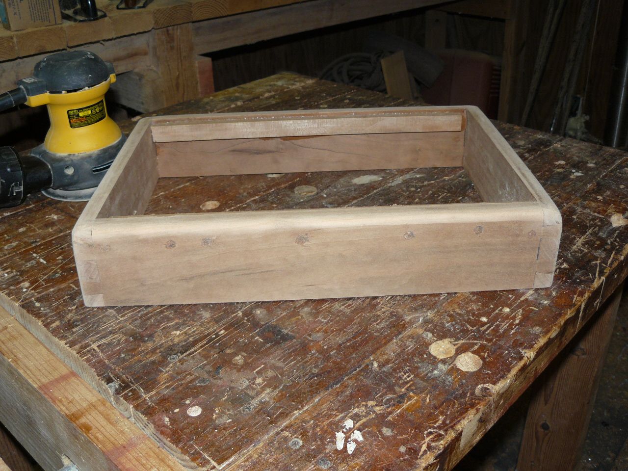
Not a lot accomplished this morning but I did manage to round the top of the case with bit and router and do some sanding. Made up some more filler and filled some tiny pin holes. Now just wait for filler to dry and do more sanding tomorrow. Before I can proceed with drilling holes I must take the old amp apart since I am going to be using the iron sockets and some other accessories for this new case. I plan on using new components to build the rest of the amplifier so I need to make an order with Mouser. I do not expect it to cost that much to use new caps. I pretty much have all the resistors I will need in stock. Remember only the two filled holes on the end are going to show. The rest will be covered by the aluminum face plate. Right now I believe it is going to be presentable because they do not stand out that much.
-
No comment on the why two cathode resistors on the input tube? What is not shown on the above schematic is a switch enabling just one cathode resistor or both in parallel which will increase the current through the tube changing the sound. Shown on the Decware website but not on the above schematic. Savvy tech guys understand why and how. A switch is not that expensive to add so I may give it a try.
-
It is here. https://community.klipsch.com/index.php?/topic/217039-new-amp-project/
-
Hey guys, some may question why another SET. Easy to build is one good reason. 🙂 Seriously though do you want to hear what your CD, or other source, is supposed to sound like? With a SET you have as few parts between your source and speakers as one can. Steve brags that there is only 6 parts between your source and speakers with his amp. Every component is going to influence the sound to some degree. Often most will never hear it but then there are those that can. An SET is for purist wanting to hear the program as the sound engineer intended it to sound. Best for one person though is not going to be the best for everyone. Many prefer an inflated sound whether bass, treble of even mids. Most often inflated bass is what many consider as better when actually it is just inflated bass. It is fine though because this hobby is just entertainment and you only have to please yourself. This is a simple build which I estimate will cost less than $600, 1/2 the price of the retail one. Below is a chassis ready to be drilled for all the components for those without a wood workshop. I said $600 using this case for $200. Iron is going to be slightly over $200 more with less than $200 for tubes, sockets and electronics. Just rough figures for anyone interested. https://www.ebay.com/itm/114550529401 The amp consist of 3 simple circuits to build, PS section, input tube circuit and output tube circuit.
-
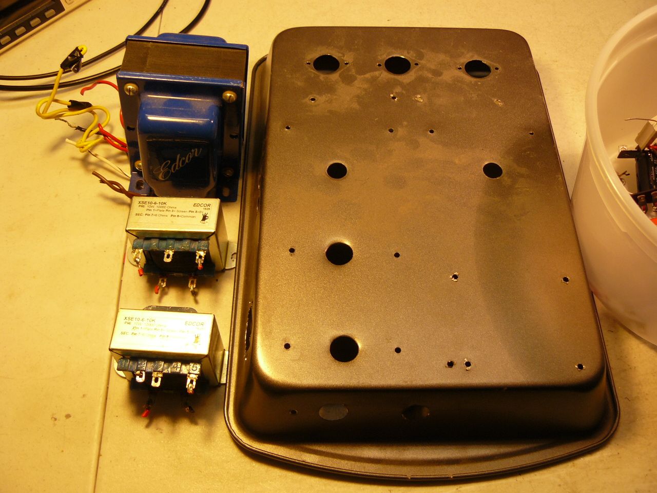
I already have a few questions to ask our talented members now. I am curious why Steve chose to use two resistors in parallel on the input tube instead of the customarily one. The value of the two resistors is approx 960 ohms measured with my meter. Steve is not running much current through that input tube somewhere less than 2ma. The tube itself is capable of handling much more. From what I saw doing the test he is running the output tubes approx at 9.45 watts of a approx 12 watt tube. About the figure I try for in my builds when biasing an amp myself, approx 80%. You will notice Steve uses just one cathode resistor for both OPT's. Not a common way of doing it but he could possible have his reasons. This schematic also shows his trick with the capacitor on the suppressor grid of the 6P15P tube. Just thought I would mention I came across a deal on some Hammond 125DSE OPT's on Ebay I thought about using on this build but those Edcor OPT's sound and test really good at the power level of this amp. George Anderson did some extensive test on those Edcors and found them to go really low when only using 1 watt, the typical level I am going to be using the amp. I also also considering using a tube for rectification as the retail amp but that Edcor PS transformer does not have a 5 volt tap. I prefer a diode for rectification myself but I am sure a tube would bring some personality to the sound. Instead of buying a new PS transformer with a 5V tap, those things are expensive for a cheap diy'er I may consider purchasing a 5V, 4amp transformer just for the rectifier tube. But then I may not. It sounds really good as it sits right now built on a baking pan. Comments, thoughts welcomed.
-
Just thought I would mention, I thought about doing this on the diyaudio forum but most of my friends are members here and if the bosses do not mind I will continue. The Little Sweetie project had a ton of views and post and I believe it was an asset to this forum but others may disagree. We will see how it is received. Just an old man occupying his time doing something constructive. I depend on Maynard and others to join in the conversation. Below is a published schematic of an earlier version I assume.
-
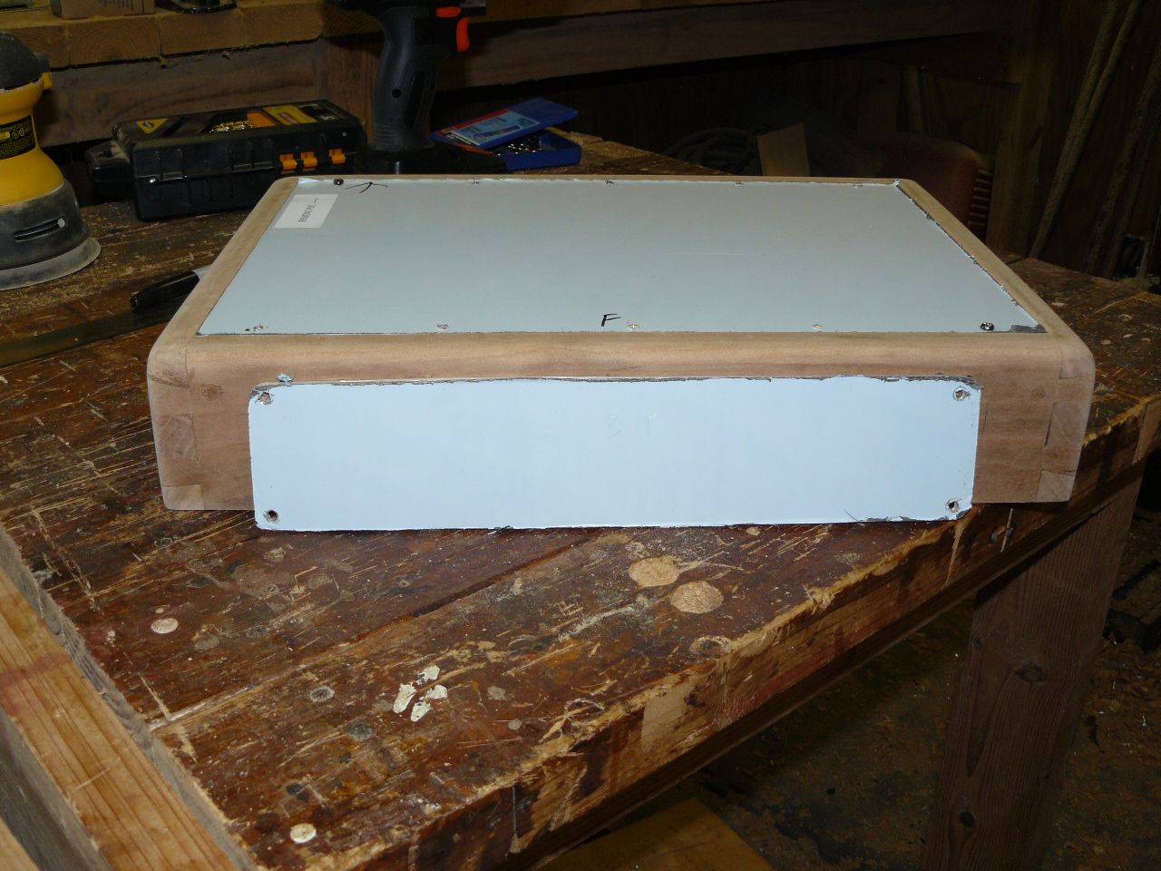
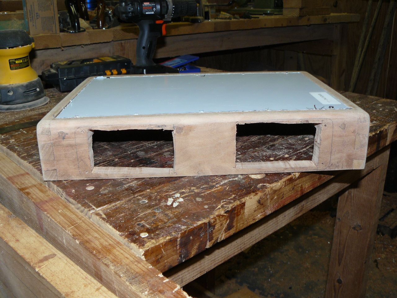
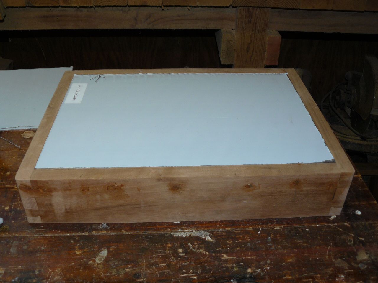
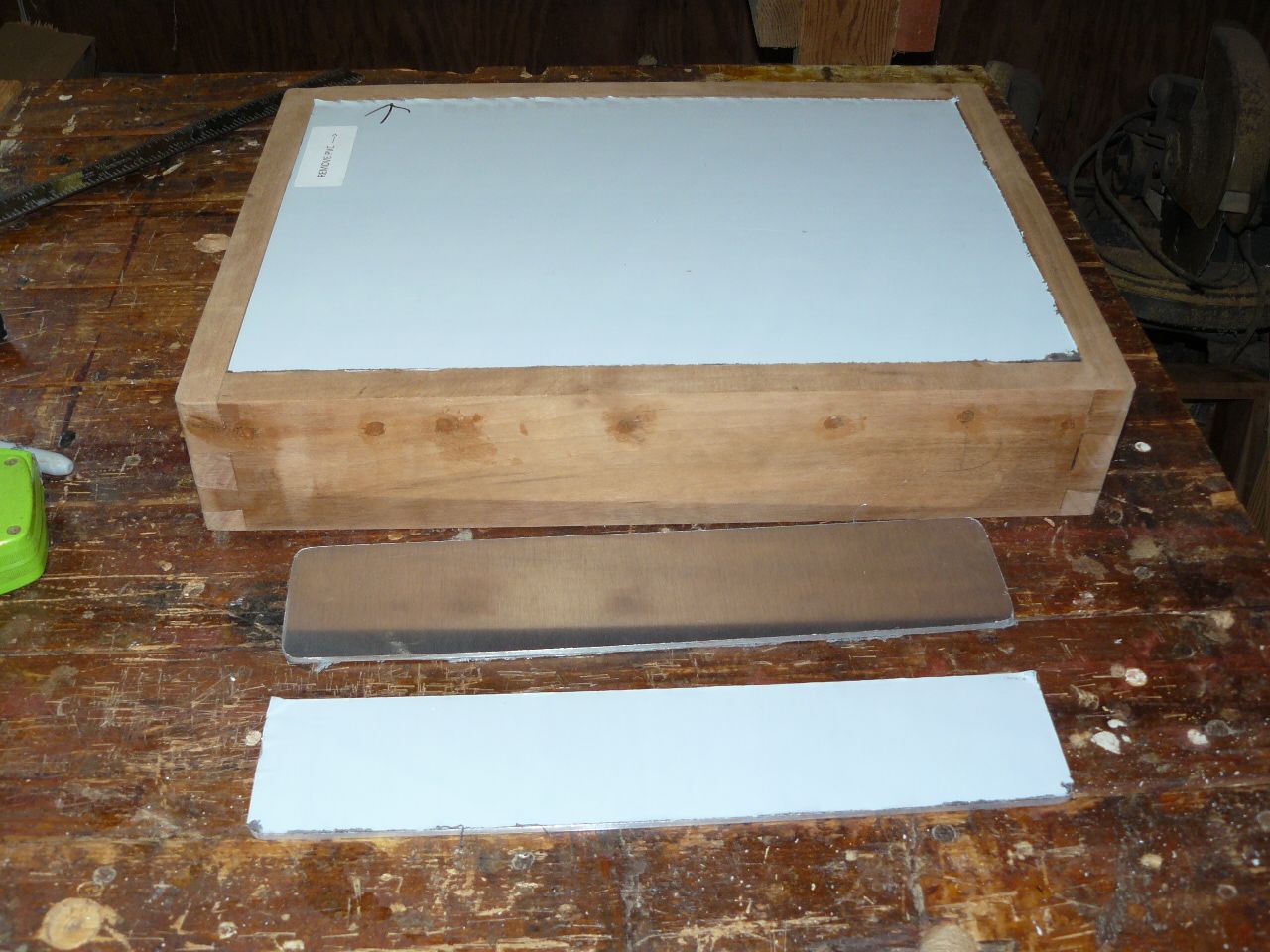
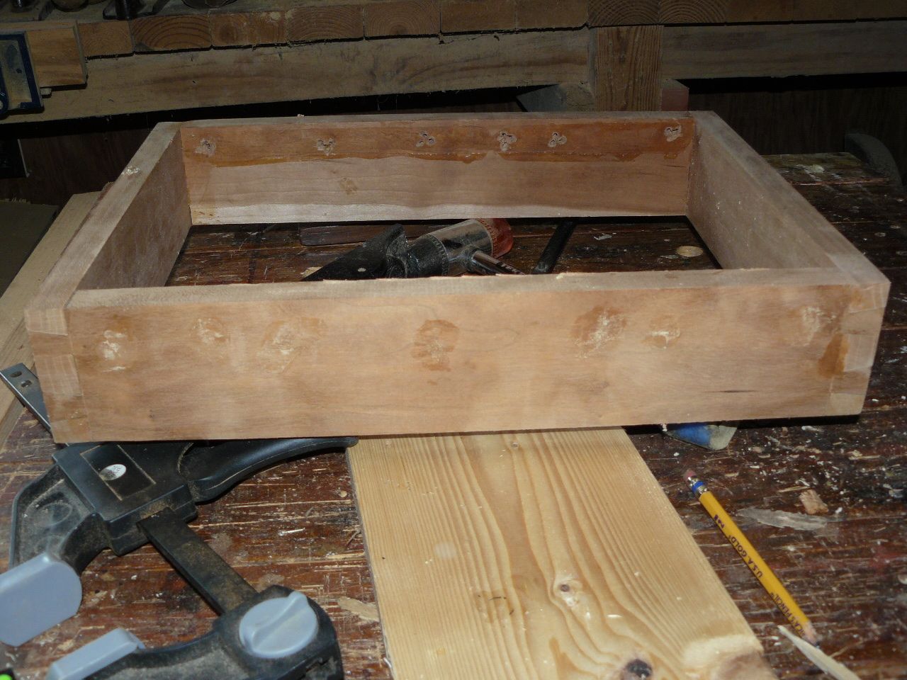
Here are pictures of what I was talking about, fitting the sheets to the top of the case and pictures of the metal that will be for the front and rear covering those ugly holes.
-
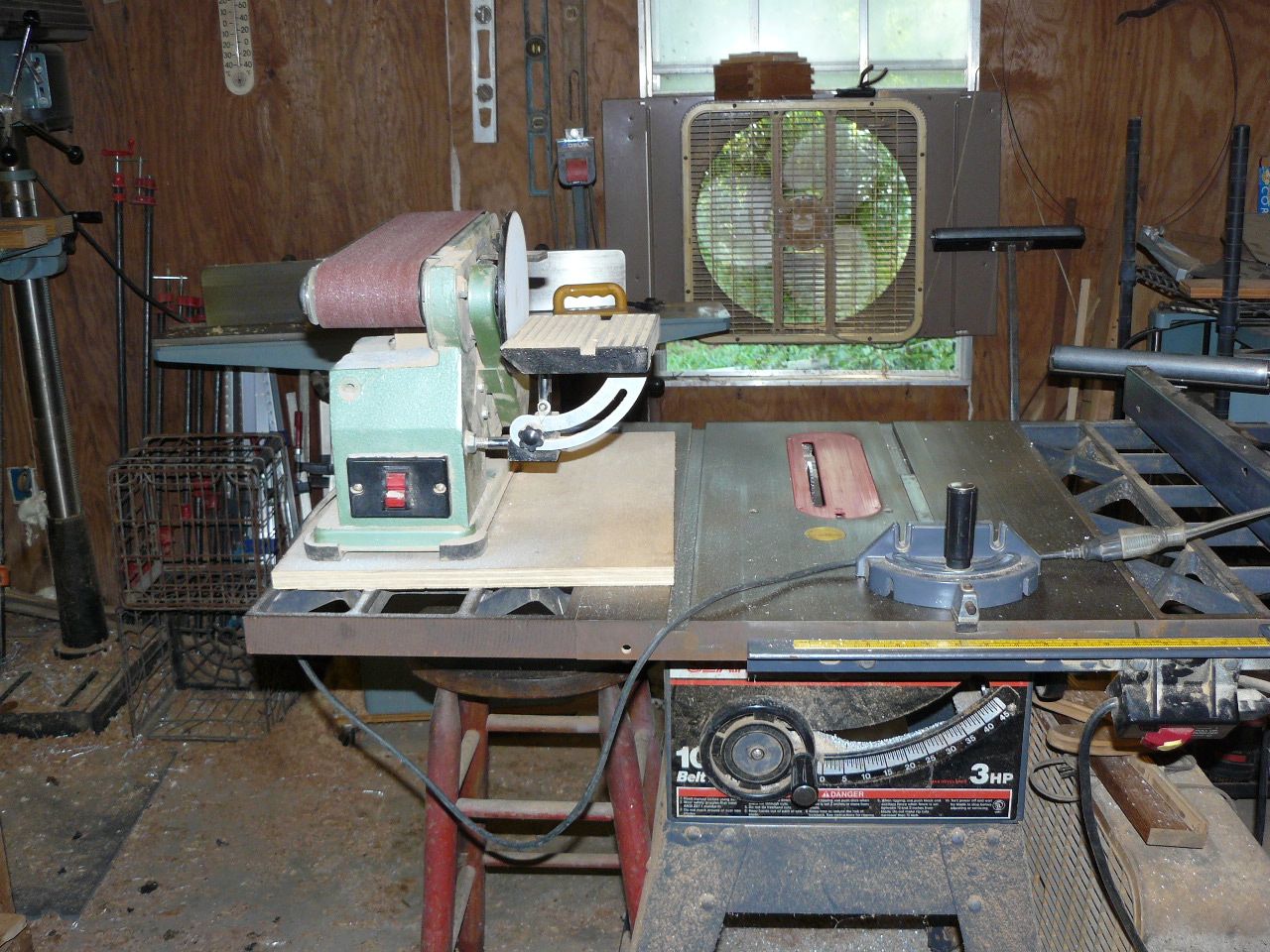
Here are some pictures of the case I am using. The problem with a follow along build is everyone can see my mistakes, errors and general miss steps but I make them and they seem to be more every year I age but I am willing if there is an interest. I am able to only work a few hours a day especially when the temp is over 90F down here in the deep south. I mentioned mistakes because I messed up bad on the wood case. I had a bright idea to use my staple gun to secure the runners that hold the top plate while the glue dried. The nails were too long and protruded to the front of the wood. I am making plates large enough to cover all of them except one on each end. Since this is just a project for myself when finished I can live with it. The saw and sander is shown to show how I custom fit the metal to the top of the case. I want a tight fit with no visible gaps in the sides so after cutting the sheets to size I use the sander to slowly fit the metal where it looks good.
-
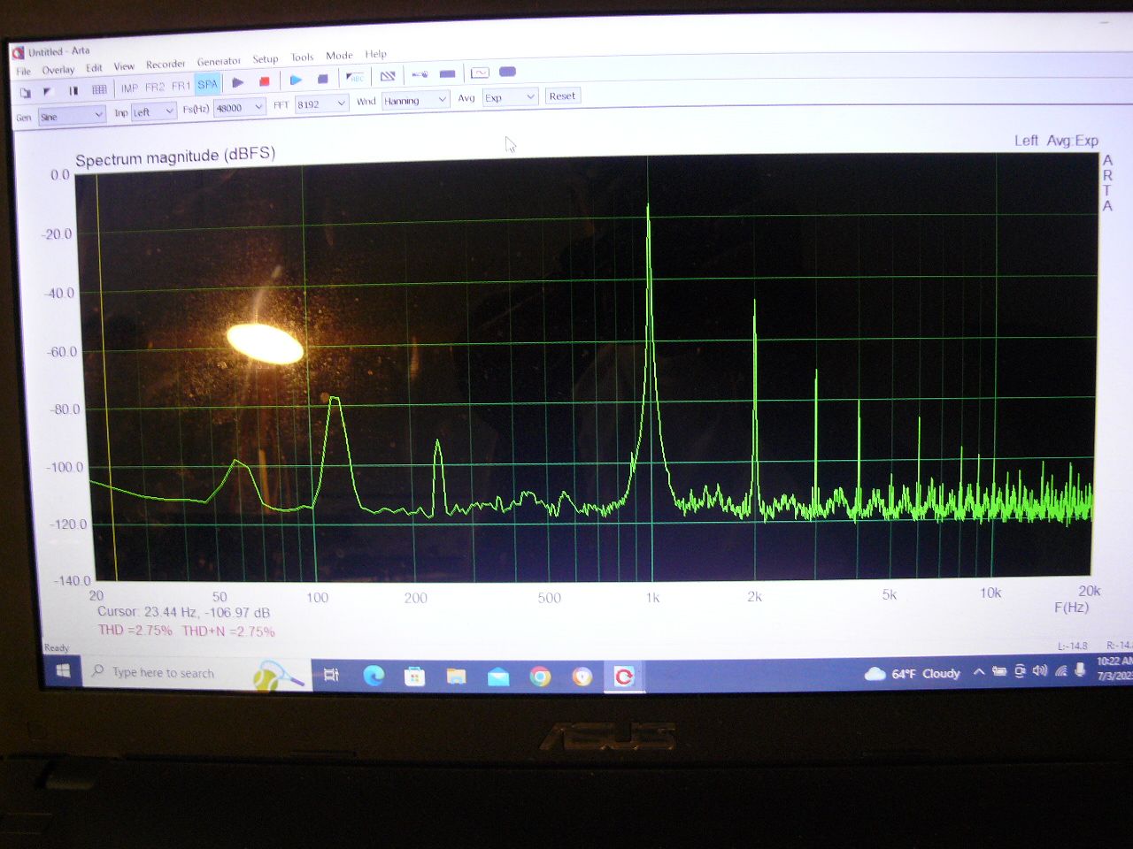
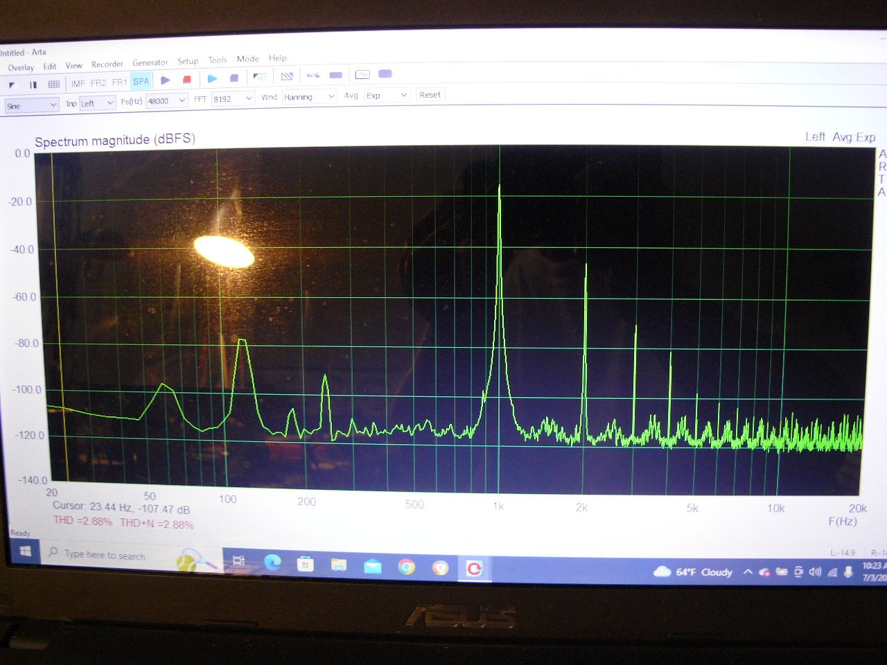
Before taking it apart I decided to do some testing to see what I am working with. My numbers are really close to what the Zen manual states which are really good, comparable to the Little Sweetie by our tube guru Maynard. Here are some pictures of the testing I did. These are the numbers at 1 watt into an 8 ohm load. The distortion numbers are predominately 2nd and 3rd harmonics, pleasant sounding. I pushed the amp to clipping and measured L 1.6 watts and R 1.45 watts. The difference in Steve's published 2 watts have to do with the output transformers I am using which are 10K on the primary of the OPT whereas Steve uses a lower value. He use to use 8K but that could have changed.
-
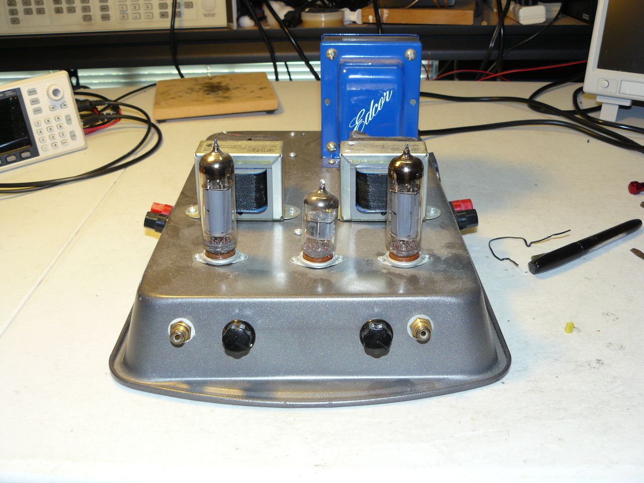
Not sure if there is an interest in members following along on an old mans amplifier build. This is an amplifier I built probably close to 10 years ago when I first started playing with tube circuits. Let's call it a breadboard build but on a cake pan. It was never meant to be shown. It is based on a public schematic by Steve Deckert's Decware Zen. I tried finding it on the net but it seems to be hard to locate but there are other pictures of later versions with schematics with some of the values missing. Not a big deal for someone with some electronic training to bias and build themselves. There are actually some schematics floating around with the values. Here are some pictures of what was built years ago.
-
Would you call the differences dramatic or just subtle to the casual listener?
-
I believe you assumptions are right except for the fact the K-horn mid and treble horns are higher in the K-horn It does make a difference in the sound you hear. In general terms, the K-horn being taller should sound slightly better. Certainly different. Not enough difference IMHO to matter that much though for someone considering buying either speaker. From your testing and reviewing of the Cornwall avs Lascala I lean towards the Cornwall as best buy when price is considered. Big difference in price between LaScala and Cornwall now. I consider the bass plenty good enough with either speaker. Different sure but both have outstanding bass. Treble pretty much the same as well. The difference is the mids where music lives. The better sounding mid is what I would want to buy.