captainbeefheart
-
Posts
1422 -
Joined
-
Last visited
Content Type
Forums
Events
Gallery
Everything posted by captainbeefheart
-
Crossover Capacitors and Crossovers In General
captainbeefheart replied to Curious_George's topic in Technical/Restorations
YAY!!! I've been dying to build one but don't have the speakers for them yet. Mine will be a tad different and cut down on a huge expense, the output transformer. My end game system includes something I have been wanting to do for a very long time but I just do not have the time. When I retire is when I'll start the process. I want to build my own large panel electrostatic speakers and fill the low end in with two subs. I figure then I can run a few kV's to the plates and bias the panel directly off the plate. I'll probably need plate chokes which is another part I have been wanting to do, wind my own. Then I can start winding output transformers also once I get decent but a choke should be easier to start with. -
Crossover Capacitors and Crossovers In General
captainbeefheart replied to Curious_George's topic in Technical/Restorations
Oops my mistake, I was thinking of a different Welborne amp............Moondog I think. I just looked at the Apollo and wow completely different!! The KR 842vhd is a completely different tube able to deliver much more power and it also has about 1/3 the plate impedance of a 2A3. I must have interpreted your post incorrectly, or Nick saying your experience with tube amps was less than overwhelming put in my head that you didn't like any of the tube amplifiers that you just listed. I think the first paragraph you listed are amps you enjoyed? And the Wright amp was just an example of one you didn't like? Oh well, it really doesn't matter. I just feel bad interpreting others post incorrectly. I'm glad we had this conversation because it brought attention to those Apollo amps which are very interesting and I have never seen before. I can't find any information about them besides subjective reviews. I want cold hard facts and specs lol I always have interest in tubes I have never used before to build with but I hardly see myself building with the KR 842vhd as they are disgustingly expensive. I'll just find some less expensive transmitting tubes to make a high powered SE amplifier. On that note I know a guy that has 150wpc SET amplifiers using the 833c transmitting tube. He spent $10,000 on just having the output transformers wound from Monolith. Those amps are insanely awesome. -
Crossover Capacitors and Crossovers In General
captainbeefheart replied to Curious_George's topic in Technical/Restorations
No surprise there, they will have the hardest time driving most Klipsch speakers. Hardly any damping, maybe a DF of 2, high distortion. That type of amp will gain a lot from a flat load vs frequency. Welborne Apollos and Canary 300b amps are in the same exact situations as the Wright 2A3. I don't know what the other amps are except the Quad II which should have given probably the best results from all the amps you listed. What did you think of the Quadd II amps? -
Crossover Capacitors and Crossovers In General
captainbeefheart replied to Curious_George's topic in Technical/Restorations
@Crankysoldermeister it might be fun to walk through a load line design with you to show how a power tube will behave to a difference in the two different loads. So for a 5k:8 transformer it has an impedance ratio of 625:1 and so with a 30 ohm load on the secondary the tube goes from seeing 5000 ohms to 18750 ohms. That's almost 4x times the resistance. You will certainly get reduced power with that load on the tube and far greater distortion. The swamping resistor keeps the tube seeing the 5000 ohms it wants to see. -
Crossover Capacitors and Crossovers In General
captainbeefheart replied to Curious_George's topic in Technical/Restorations
Not necessarily. Remember that the flea watt amps are tube amps. The tube needs to see a specific load and we design the amplifier that way. The output transformer reflects back the impedance of the speaker to the tube. So if we design the load impedance for the tube at 5k:8, that means we want the speaker to be as close to 8 ohms as possible to get the optimal results. Once a frequency hits that 30 ohm impedance part of the curve the tube will see a MUCH higher load on the primary which for a Pentode/Tetrode will bring the load line down far below the knee and sound awful by producing nasty sounding distortions. Power through the mid-horn doesn't change but now you have much higher distortion right in the most important part of our hearing. They are much different than solid state amps which is why I broke what happens into two categories. So for a tube amp, it's designed for the 8 ohm load so the resistor is just keeping the tube in it's linear region, not a bad thing at all. -
I have 1975 Heresy's also and mine were in great shape when I inspected them recently. The only thing I might replace is the gasket as it was a little stiffer than a new one but it was in good enough shape to function properly. If the gaskets are very dry, midrange?
-
Crossover Capacitors and Crossovers In General
captainbeefheart replied to Curious_George's topic in Technical/Restorations
I read through what he said in that link from a different thread and I agree. Loudspeaker efficiency as a system and Loudspeaker sensitivity are two different things. With Al's network the total system efficiency drops but sensitivity stays the same. That's why I gave the example of a specific amplifier with a specific amount of loop gain, with the volume control at the same exact level the two systems will have the same acoustical output. The amplifier does need to deliver extra current hence the efficiency is reduced. Now people that have experience with the networks know the acoustic output isn't the same but that's not because of the resistor, it's because of the lower chosen output tap. Some people claim the mid-horn is two in your face as it is. When leaving the auto-former at the same output tap as stock, increasing the the 13uF to 48uF and adding the 10 ohm resistor actually increases amplitude to the mid horn at 1kHz. It's just too much mids so the horn is taken from the next tap down on the auto-former putting the amplitude around -1.5db compared to stock. So yes less acoustic output but by choice from the auto-fomer. The swamping resistor isn't stealing any power away from the mid-horn. Think of a 10 ohm resistor as load connected to a 10v battery. We get 1 amp of current and 10 watts of power through the resistor. Now add another 10 ohm resistor in parallel, The battery sees 5 ohms, and so produces 2 amps of current. Each 10 ohm resistor is dissipating 10 watts of power. The original resistor has not changed, it produced 10 watts before and after adding the second resistor. BTW i got a kick out of that little article about increasing the power handling capability and grossly lowering system efficiency by adding the two resistors to keep the amp seeing a constant impedance. 1200 watts to get the same acoustic output as originally only needing 1 watt🤣 -
Crossover Capacitors and Crossovers In General
captainbeefheart replied to Curious_George's topic in Technical/Restorations
I'll have not read it but will peruse through it -
Crossover Capacitors and Crossovers In General
captainbeefheart replied to Curious_George's topic in Technical/Restorations
With Polyester/foil the film thickness is much thicker, 5uM compared to .05uM. That alone will give them far different properties. I mean literally the physical size and construction between the two are very different. -
Crossover Capacitors and Crossovers In General
captainbeefheart replied to Curious_George's topic in Technical/Restorations
Looks like it's about -1.5db lower than the stock network at 1kHz so yes with his networks the mid-horn has a reduced acoustic output, but as I mentioned this is not from the resistor, it's from the auto-former tap change. -
Crossover Capacitors and Crossovers In General
captainbeefheart replied to Curious_George's topic in Technical/Restorations
You know what, you are correct, I just noticed he moves the tap down another peg which makes sense because as I showed without moving it down it's actually hotter with the changes. But what I did show is it's not the resistor that's causing the decreased output at mid-horn. I'll figure out what is the output with the different tap compared to stock network. Thanks for your short but accurate response since it made me go back and look -
Crossover Capacitors and Crossovers In General
captainbeefheart replied to Curious_George's topic in Technical/Restorations
For SS amplifiers I don't really see any benefit to the swamping resistor but since you and I and many others use tube amplifiers with output transformers I think it's certainly an advantage to aim for flat impedance curve to keep the loading of the output tube consistent over the frequency range. Pentodes/Tetrodes will suffer the worst from the large 30 ohm impedance right in the midrange, nobody wants gross distortion in the most important part of the audible frequency spectrum. Triode output stages if output impedance is sufficiently low enough (<1 ohm) shouldn't be affected so badly and may even get a slight reduction in distortion from the higher load impedance. Here is a trick some of you may know. With a Pentode/Tetrode output stage this rise in impedance can be mitigated by using a Zobel network at the output. The values may need to be tweaked from typical network values that expect a rise in impedance at higher frequencies. Whenever I build Pentode/Tetrode amplifiers I always have a Zobel network to keep loading flat. Some well designed Pentode/Tetrode amplifiers have these networks but MANY do not. I truly believe that's why PWK liked the Brook amplifier so much with it's Triode output stage and negative feedback. It had low enough output impedance to handle the varying impedance and the Triodes handle it better with no Zobel compensation added. -
Crossover Capacitors and Crossovers In General
captainbeefheart replied to Curious_George's topic in Technical/Restorations
Yes I didn't want to imply you don't know what the resistor is there for. I'll try and explain from a different approach. Let's just go by simple concepts that a normal person will notice using said equipment. An amplifier has specific loop gain, I'll use an amplifier that has a sensitivity of 20db, which is a gain of 10x. Let's say we have the volume control set to where there is 1v input, the output will then be 10v. Let's leave the volume control at this exact same place for both sets of speaker with the two different networks, one with a swamping resistor and the other without it. This is a complimentary emitter follower output stage like most amplifiers out there. We won't use a tube amplifier for this explanation because it's a completely different result and most people will be using modern SS amplifier. Voltage will be peak voltage btw. With the network without a swamping resistor we will be about -6db out of the auto-former going into the mid-horn. That gives us 5v across the driver and if we assume 8 ohms then that's a peak current of 625mA. With the network with the 10 ohm swamping resistor added (don't forget the 13uF is now much larger) we have -4db at the output of the auto-former which is 6.3v and a current of 787mA through the driver. So for the same exact amplifier, with the same exact level of volume control setting you actually will have slightly more output from the midhorn. Overall speaker to amplifier relation for a given volume control setting will yield similar sound pressure levels, actually slightly higher with Al's network so his midhorn will be a little hotter. Yes I did add the other components into my analysis like the .3mH series inductor and 2.2uF shunt cap, these are just to filter high frequencies from going to the mid horn anyway. Yes the resistor gets hot, and yes the amplifier needs to supply that current to get it hot but given the same amplifier, with the same volume control you lose nothing in way of sound pressure out of the speakers. That extra energy going into the resistor would be comparable to a normal loudspeaker system without an auto-former so you do not need to increase amplifier power to get the same sound pressure. Hope this clarifies things better. EDIT: The analysis was for 1kHz signal -
Which amps maximize the bass output from Heresy IV's
captainbeefheart replied to Tiffiny's topic in 2-Channel Home Audio
I never said to go off the published -3db and understand what you are saying. I agree one will need to experiment to find these spots. I was only trying to give a basic concept of where to have them overlap is all. I didn't mention published specs or specifics for a reason. It's good you went into detail to deter people from going by a published spec. I only wanted to say you want them to overlap in the region where they both are roughly -3db down because the two sound sources will sum which might not occur to some people and they may aim for having them overlap too much or too little. Thank you for adding what you did, it will help people better understand room interactions and help them in the efforts to blend the two together better as you cannot just go by published data for the speaker. It's possible some simple apps on peoples phones can help find these spots where their loudspeaker -3db point is in room. The Sub is obviously adjustable and can be set wherever so one only needs to find data for their loudspeaker, in this case the Heresy. -
Which amps maximize the bass output from Heresy IV's
captainbeefheart replied to Tiffiny's topic in 2-Channel Home Audio
* -
Which amps maximize the bass output from Heresy IV's
captainbeefheart replied to Tiffiny's topic in 2-Channel Home Audio
The reasoning is because adding two speakers together with similar sound volume usually yields +3db in sound pressure. Where on the other hand if they intersect at -3db the reduced signals sum to make it flat again. If you have to much overlap without enough attenuation you'll get a +3db boost at the crossover frequency above 0db/flat. -
Which amps maximize the bass output from Heresy IV's
captainbeefheart replied to Tiffiny's topic in 2-Channel Home Audio
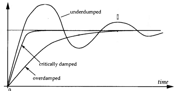
Damping factor is a poorly understood concept. You don't need as high a ratio as many people claim. Firstly because even if the amplifier has a ridiculously low output impedance the speaker wire and woofer low pass inductor will just bring it right back to average levels since they are in series with the driver and amplifier. How manufacturers actually get these high DF specs is they are measuring it from within the amplifier to remove the series impedance of the speaker wire and speaker jack. The second reason is a little more complex. Under-damped is when the system reaches 0 amplitude very fast but oscillates back and forth until it settles and stays at zero. This is worst case scenario which is why an adequate amount of damping is recommended. What is misunderstood is my next point. Over-damped will cause the system to take longer in time to reach 0 amplitude. There is no oscillation which is good. But the motor takes longer to stop. Critically-damped is the best case scenario. It reaches 0 amplitude in the fastest time possible and there is no oscillation. Basically too much damping can be a bad thing, causing the time it takes for the motor to stop moving to be increased. Ideally you would like to shoot for a critically damped system. Back in the old days there were more amps with "damping controls" which I thought was a great idea. It's a way for the customer to be able to dial in the fastest settle time with different loudspeakers. You hardly ever see them anymore on amps.
-
Crossover Capacitors and Crossovers In General
captainbeefheart replied to Curious_George's topic in Technical/Restorations
It's confusing but let's look at it in more depth with specific amplifiers. With a solid state amplifier, voltage source amp like 99% of them. The speaker is rated for 8 ohms anyway and so the amp will have no issues with the resistor in there, it's as if it were driving a more flat speaker system rated for 8 ohms that doesn't use an auto-former. I don't see why Al is so hung up on making the amp care to see 8 ohms at those frequencies with a SS amplifier. Current is reduced through the mid horn from the higher series impedance of the auto-former which reduced it's output. Goal is achieved so why care what the amp sees? I don't see it as any issue whatsoever. The only issue I can see is when using a tube amplifier (pentode/tetrode operation) with an output transformer. The transformer reflects the load of the speaker back to the tube. We would like to keep the load of the tube as consistent as possible for linear performance across all frequencies. With the 30 ohm load at the secondary of the output transformer it's going to reflect back a MUCH higher load to the tube. For a triode output tube this isn't an issue. Possibly why PWK's favorite amplifier was a Brook tube amp with output triodes. BUT, with pentodes/tetrodes if the load is too high it brings the load line down below the knee of the curves which gives worse performance. The load is no longer optimal, higher distortion is the product. So solid state amps why waste power through the output transistors with the swamping resistors? I see no advantage whatsoever. If I'm wrong and their is an advantage please correct me. With a tube amplifier it's worth having the swamping resistor in the network so the reflected load back to the tube is in it's correct most linear part of it's operation. So there you have it. If you run a SS amp the networks are fine without the resistor, I don't see the amp caring about seeing a 30 ohm load and less heat is wasted through the output devices. With a pentode/tetrode output tube amplifier with output transformer then you may want to try the swamping resistor to flatten out the load impedance and keep the tubes in their linear region. This is what Al refers to on his website, he incorrectly actually states a SET amp, which he assumes a high output impedance which is silly. You can of course use gobs of feedback with a SET amplifier if you have enough open loop gain and the output impedance would be very low, certainly low enough to be considered a voltage source to the speaker load and not track the impedance. He should correct it and say for Pentodes/tetrodes. Triodes typically will have reduced distortion as load impedance increases. Too high an impedance and you don't get much current change at all and little power into the load. We find happy middle grounds with triodes to achieve power at a satisfactory level of distortion. It's all about the plate load characteristics of different types of tubes. -
Crossover Capacitors and Crossovers In General
captainbeefheart replied to Curious_George's topic in Technical/Restorations
Basically look at it this way. Given the same exact output voltage the speakers will have the same exact output in sound pressure with or without the resistor. The difference is at certain frequencies (midrange) the amp will produce more current but the output pressure is the same from drivers. So yes overall system efficiency is reduced, but it doesn't cost you any sound pressure out of the speakers with you having the volume control at the same exact spot. E.g. The speakers will have the same sound pressure output at the same spot on the volume control. You don't need to turn the amp up any louder like you would with a harder to drive set of speakers. The amp works a little harder is all at those frequencies. -
Crossover Capacitors and Crossovers In General
captainbeefheart replied to Curious_George's topic in Technical/Restorations
The resistor costs the speaker zero loss in regard to sound pressure out. It only costs the amp some power that wouldn't be going through the squawker anyway. It's purpose is the auto-former is there to reduce the signal to the squawker, the issue is it squares the squawker impedance by the amount of turns; i.e. it increases the impedance the amp sees to 30 ohms. The resistor is only there so the amp sees a flat response at 8 ohms instead of 30 ohms. The same amount of current flows into the squawker with or without the resistor there so sound pressure remains the same. The amp needs to supply extra current which passes through the resistor. I.e. it doesn't take any power away from the drivers, it only pulls power from the amp. -
Which amps maximize the bass output from Heresy IV's
captainbeefheart replied to Tiffiny's topic in 2-Channel Home Audio
Oh silly me I forgot an important detail. I found optimal performance having the Sub-woofer high frequency roll-off point at the same frequency as the Heresy low frequency roll-off. Once you dial in where the Sub's attenuated point (depending on the slope) meets where the Heresy's attenuation point it sounds more natural. Also make certain you have the phase of the sub-woofers match the phase of your amplifier powering the Heresy's. -
Which amps maximize the bass output from Heresy IV's
captainbeefheart replied to Tiffiny's topic in 2-Channel Home Audio
If you like the deep bass, you know EDM shake the house dance music bass Heresy's and most hifi loudspeakers don't go low enough since they have only a woofer. I mean don't get me wrong most of the detail is in the woofer frequency range but the frequencies you feel are below a woofer, hence the sub-woofer. I'd say you are off to a great start with the Heresy Loudspeakers and the sub-woofers. Many of us that have huge loudspeakers still use sub-woofers. It takes a ton of energy and lots of driver displacement to get excellent bass so it's optimal to split it up anyway with loudspeakers and sub-woofers being separate. The Sub-woofer can require gobs of power, at least for me 250 watts is good but you can go up to over 1000 watts with the sub woofer unit. I recommend Class D sub-woofer amps since they are light weight and very efficient but whatever you have keep it if you like it since, well....you already have them lol. This allows you to focus higher quality amplifiers for your Heresy Loudspeakers where all the magic is happening. I'd say you do not need to change amplifier that's driving the Heresy's if you like how everything sounds with the subs and Heresy's together. There are some loudspeakers that can do it all but I find that very few and far between. I personally like keeping them separate. -
Crossover Capacitors and Crossovers In General
captainbeefheart replied to Curious_George's topic in Technical/Restorations
This would be the debated aspect even if we show different plots with different capacitors. At what point is something audible? In the instance of balance/crossover networks I am not seeing distortion as going to be a huge influence, speaking about just capacitors since there isn't much of a signal across them. When I measure distortion or linearity in capacitors I have push a lot of voltage across them to show it, they are the entire load not a very small portion of the load. I'd wager it was what was alluded to by "voltage transfer", basically amplitude vs frequency of the filter networks. Even at 20kHz a 2uF cap is still 3.9 ohms differences in ESR aren't going to make a huge difference, there will be a difference but is it audible? If the tweeter is even 8 ohms at 20kHz; With an ESR of say 1 ohm vs .01 ohm we get 67% and 62% respectively. So I suppose the higher ESR gets you'll reduce amplitude out. I would think 1 ohm at 20kHz is a pretty bleak ESR for a film cap so a good worst case scenario will lose 5% of the output at 20kHz. How good is hearing up at 20kHz? Is it sensitive enough to notice 5% difference? These are more the questions we will end up with after we get the measurements. -
Crossover Capacitors and Crossovers In General
captainbeefheart replied to Curious_George's topic in Technical/Restorations
Exactly why I say construction can have an impact on the variables. The rolled types still are made but for the competitive capacitor manufacturers for high frequency, fast rise time switched currents they have been stacking the layers in different manners and instead of having one lead at the inner foil roll and the other at the outside foil roll they offset each plate to one side of the package and the extended part of the plate is connected to the lead, this give much more uniform characteristics. Here is an image.
-
Crossover Capacitors and Crossovers In General
captainbeefheart replied to Curious_George's topic in Technical/Restorations
What he means is the output impedance from most SET amps is high due to them not using any negative feedback from the output to lower it. Since the output impedance is so high with any variation in load impedance you get large voltage differences. An amplitude vs frequency plot shows this well and isn't a straight line. The amp behaves more like a constant current source than the ideal voltage source. With a voltage source the voltage stays relatively the same and current though the load changes. With a current source the current through the varying load stays relative the same but voltage changes. He is saying his networks are flat for impedance vs frequency.