NateAUS
-
Posts
6 -
Joined
-
Last visited
NateAUS's Achievements
Newbie (1/9)
1
Reputation
-
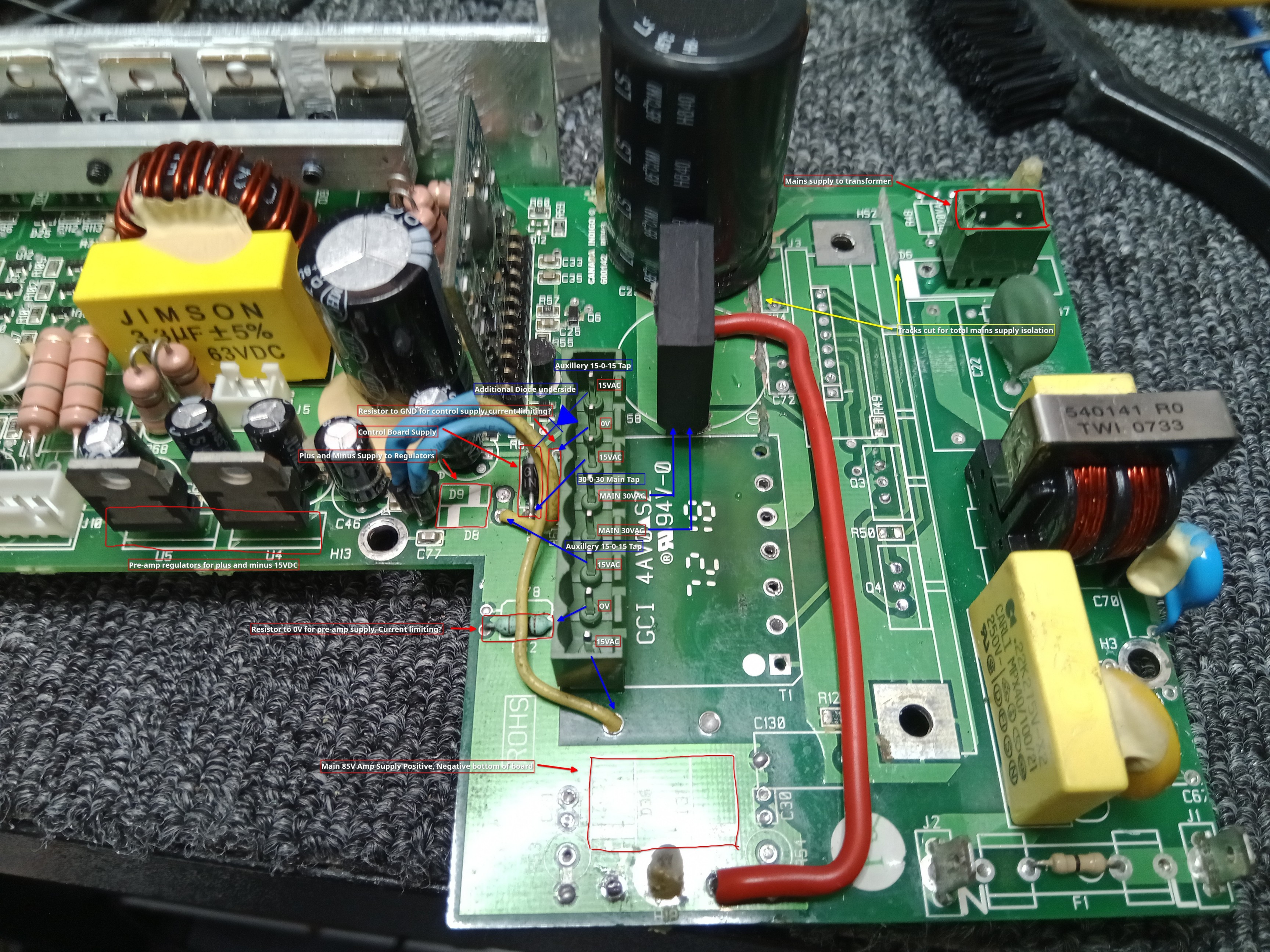
Hopefully this gives an idea what I have done. It was very hard to keep the high current/voltage section for the amp tidy as I was trying to reuse as much of the original board as I could. If I was to do it again I would probably do it a little different to to make as nice as possible. Main thing is that it works very well, is safe and will be very robust. At some point I will change the other supply caps but they are OK for now.

-
I will provide photos as I want to tidy up a few things now I know it all works well , so when I can pull it apart (there is nothing more permanent than the temp fix that works haha) I will send through how to do it, its actually very simple and works well. The original supply has 3 separate output sections : 1) Main power for the amp section 2) plus and minus for what appears to be the pre-amp section which has a 7915 and 7815 regulator and finally a supply for the control section. When I got the orignal supply to actually kick in I measured around 85VDC for the main power, 28VDC plus and minus at the regulators bit I never got the test the control section. I used a 160VA toroidal transformer 30-0-30 and two 4.5VA 15-0-15 . I had to use three transformers as the one I wanted which was 300VA 30-0-30 with 15-0-15 and 12-0-12 auxiliaries, was out of stock. The 60VAC just needs to be rectified and put to the main 85vDC rail, the 15-0- 15 I put through a bridge where the original rectifying diodes were and the other 15-0-15 i put through two diodes as a full wave rectifier to the control section. As I knew two power supply voltages I powered those up and then using a bench supply connected to the power section I slowly brought the voltage up (with current limiting just on case) till the circuit kicked into life which was around 17VDC. The plus/minus rail only produces about 21VDC not the original 28VDC but as it is regulated down to 15VDC anyway it just makes the regs not have to work so hard. Once stock of the 300VA becomes available I will be able to remove the 3 transformers and replace with the one. The only thing I havent tested in this scenario is whether the 12-0-12 rectified will be enough for the control section but I believe it will be as once rectified 12VAC will be around 16.8VDC. It took longer to work out how than actually doing it. Anyway I hope this kind of makes sense. I will try and show on the photos the connection points. The only thing I will say is please only do this if you are qualified to do so!!
-
I have the Klipsch Sub 10
-
Just thought I would add to this discussion. I have a sub-woofer with the same power supply issue. Found a couple of stuffed zener's which got the switch mode supply oscillating but not reliably so I knew caps were a problem as well. I decided that the design of this supply is very weak and to rip it out completely. I removed all the PSU component's off the PCB till mainly just the amplification part was left. Then I fitted a 300VA toroidal transformer and its works beautifully. Now I dont have a supply that can fry up anymore and should be much more reliable than the original. The worst part of doing this was removing all the unnecessary parts off the original PCB esp the small transformer and the bridge rectifier. I can go into detail if someone whats to know how to do it
-
Switch mode PSU's are known for killing capacitors due the the high frequencies being used, but I would not expect failure after a year normally around 5 years.
-
I can verify replacing the capacitors on the PSU is a better option and works, the STB signal enables the 24V power for the Amplification circuit otherwise power will be constantly on. A $1 worth of parts makes for a very cheap and quick repair I changed out both C05 and C06 16v 220mf. I used the ESR type which are designed for this application.