Al Klappenberger
-
Posts
3918 -
Joined
-
Last visited
Content Type
Forums
Events
Gallery
Everything posted by Al Klappenberger
-
A question about large X-over networks
Al Klappenberger replied to MechMan's topic in Technical/Restorations
My "Universal" network is NOT suitable for a Cornwall OR a Cornscala and can NOT be modified for use in either of those speakers without a major redesign. To use it in these speakers will cause frequency response imbalance and distortion or could even damage the squawker driver. Al K. -
A question about large X-over networks
Al Klappenberger replied to MechMan's topic in Technical/Restorations
Rick, To directly answer your question, you can mount them anywhere you like. It's not important. I would like to verify that what you have is appropriate for a Cornwall becasue my "Universal" is not and I would like to verify if it was modified correctly. AL K. -
A question about large X-over networks
Al Klappenberger replied to MechMan's topic in Technical/Restorations
Mechman, Please identify what crossovers you are installing. Define "Universal style". Al K. -
On the passing of Mr. "P" ..
Al Klappenberger replied to Al Klappenberger's topic in Technical/Restorations
I was just forwarded a letter from MARK Potter via Lee Clinton along with a group of pictures that should be of interest. They are in PDF form but quite large. I will try to upload the file intact. AL K. .................. Thank you for the very kind post that you & Al compiled for my father, he was very passionate about his audio/speaker interests and really enjoyed talking to those special few folks who "got it right". We found a few pictures of Paul and Dad that would be cool to add to the post. These were not the pictures I was looking for, I know we kept a few 8x10's of Paul that Dad took that are really good. I will continue to look for them. I also found a Klispch Audio notebook/binder that Dad had...looks to be from the late 50's/early 60's that I would give to you if you thought someone would enjoy it. I have his favorite "Bullshit" button that Paul gave to Dad, that he used to tell the story that Paul would get mad at Bose and flash the button instead of actually saying it. Right now we are planned for a small memorial at the Callison and Lough Funeral Home in Bentonville on Sat the 18th--we need to firm the date up with folks coming in from out-of town, so stay tuned, we would hope that you and Paula could attend. Thanks again Mark IMG.pdf IMG.pdf -
On the passing of Mr. "P" ..
Al Klappenberger replied to Al Klappenberger's topic in Technical/Restorations
Dennis, That has got to be one of Max's longest emails! I didn't know you two knew each other, but I am not surprised. I will bet you met him the same way I did, a phone call out of the blue! He would monitor the forums and call up people that impressed him and introduce himself! The last sentence: "please answer privately." was always important to him. He had lots of inside stories that he would tell you if he trusted that they would go no further! Al K. -
Gram, I'm happy that I was finally able to make it understandable. That's not always easy for an egg-head type like me to do! Your doubts about the measurement method is quite justified. It also points up the fact that the manufacturers of woofer drivers never give you the correct information. They will tell you it's 4 Ohms or 8 Ohms and that's it. They are telling you a lot of NOTHING! The only exception I have seen is a driver by TAD that gives you values for the required Zobel in the spec sheet. It also demonstrates that fact that loudspeaker people think they know filters but few of them actually do! Lee is getting the test software too and he will be able to evaluate it properly. I would wait until he looks it over before I would buy it. In my case I actually use an HP3563a dual-channel FFT analyzer with the simple simple resistor bridge. The A and B channel display the simple Zo and polar phase directly over any frequency range I need. From Zo and Phase I convert to R +-Jx and then compute L from the Jx for any frequency I need. The dual trace oscilloscope method I describe in the on-line procedure is simply a way to do it with equipment that a person is more likely to have lying around. Al K.
-
On the passing of Mr. "P" ..
Al Klappenberger replied to Al Klappenberger's topic in Technical/Restorations
Here are two of the jewels from Max's collection that found their way to me. It's the B&K 1/2 inch mike element and the General Radio Microphone calibrator. With these and the Old Colony Mitty Mike II that he recommended to me early on. I am quite sure of my response and level measurement equipment if not always my technique! An interesting thing about Max was the difference between how he could talk on the telephone compared to his emails. Below is a quote, in it's entirety, from one email I remember well: "?" That's it! Just a single character! I knew exactly what he wanted to know! Al K.
-
Blvdre, The "Jr" is not one of the designs included in that group. I'll post it here. It's the computer drawn schematic. It's similar to the Universal but the cap connected across the transformer is not there. The part values are also different. Al k.
-
Gram, Ok.. I think what happening is that you are limiting the parameters to only two (Rdc + Xl). There are actually THREE factors. I'm going to call them Rdc + Rac and XLe. When you put an ohmmeter on the voice coil you are measuring the DC resistance of the wire. There is also additional resistive loading provided by the enclosure and all the mechanical factors involved with the acoustics. This shows up only when the speaker is seeing AC within the woofer range. It's what I call Rac. The total simple impedance would then be Square_root ((Rdc+Rac)^2 + XLx^2). If you "tune out" the inductive component with a series capacitor © and measure the resistive loss that is left at the resonance of C and Le, it will be Rdc + Rac, it will be about 6 to 7 Ohms in the K33 woofer. This is the impedance you use to design the woofer filter. Does that make sense? Al k.
-
On the passing of Mr. "P" ..
Al Klappenberger replied to Al Klappenberger's topic in Technical/Restorations
I mentioned earlier that Max was instrumental in the development of the Trachorn. I sent him the very first crude prototype I built in my garage with hand tools for him to evaluate. Here it is sitting on top his latest home-made speaker. AL K.
-
On the passing of Mr. "P" ..
Al Klappenberger replied to Al Klappenberger's topic in Technical/Restorations
Max also helped me design the "Heresy on steroids" speaker using a K24 woofer in a ported box that goes down to 30 Hz with ease. He knew what he was talking about. Here's one of the speakers he built that he thought was one of his best.
-
On the passing of Mr. "P" ..
Al Klappenberger replied to Al Klappenberger's topic in Technical/Restorations
Max was also a camera buff. I think Max took this picture, but I am not 100% sure. I know for sure that Max sent it to me though. Al k.
-
On the passing of Mr. "P" ..
Al Klappenberger replied to Al Klappenberger's topic in Technical/Restorations
What the Klipsch community doesn’t know is how much influence he has had on the all of us, mainly through me. Without Max, there would be no Trachorn and there would be no extreme-slope crossover networks. Max and I used to talk on the telephone for hours about audio. He was a collector of instrument microphones and a walking text book on how to use them. With his move from his home after his wife (Charlotte) passed away, he gave much of his collection to Lee Clinton. Several quality standard mikes came to me. Here’s several ways he influenced all of us. It was Max who first convinced me to try just sitting a set of Altec 511B horns on top of my Belles to replace the K500 squawker horn. I did it and never looked back! I mentioned to Max that I know of no horn made that would directly replace the K400 horn in the Khorn. He proceeded to describe the theory behind the Tractrix horn and mentioned that he had talked personally to Bruce Edgar to try to talk him into making a better squawker horn for the Khorn. Dr. Edgar simply had bigger fish to fry! I told Max that I couldn’t figure how to make a Tractrix horn with a square mouth. He proceeded to enlighten me on how you make the top and bottom flat and let the sides curve! Max pointed me to the article by Dr. Edgar. I was able to duplicate his design and write a program to do the design for the Khorn. The Trachorn 400 was born! I built the first one myself with great effort but was unable to find someone locally capable of making it properly. Again Max came to the rescue. He told me about Bill Martinelli at www woodhorn.com and the rest you know! So.. If it were not form Max, there would likely be no Trachorn! In another conversation with Max, the subject of driver interference came up. When I explained my filter background and how easily I could design a crossover with 120 dB / octave slopes, I got pushed into doing it and writing a technical article about it. Without Max bubbling over about how major an improvement this could be, the article would not have been written and I would likely have never offered the extreme-slope network designs! As a student of the subjective nature of the ear / brain combination, I received may dissertations on the fallacy of saying how I think something sounds! You can credit my persistent refusal to make these sort of comments and to disregard comments like this that I hear from others. This is why I stick to instrument measurements. He used to say that you must first start with the instrument measurements and then adjust things to your taste. What you like is right, for you and you only! Thanks to Lee Clinton, here is some background on Max: Max was a 1958 engineering graduate from the University of Arkansas. As an engineer for Western Electric, his early years were spent designing guidance systems for the Nike Hercules missile system. The Nike missile system was first proposed to the U.S. Army by Bell Laboratories in 1945. While Western Electric was Bell’’s manufacturing arm it also subcontracted to the defense department. Max worked at several Western Electric facilities during his 25 year career before retiring in 1983. Lee will have more to add later. I will miss Max very much! Al K -
It is with extreme sadness that I inform the Klipsch community of the passing of my friend and mentor “Mr. P”, Max Potter. He is probably best known to most of us as the inventor of the “P-Trap”, a modification to the early Khorn crossover networks to remove the 9 KHz “glitch” inherent in the early K55V (push pin) driver. He passed away Saturday (aug 28, 2010) of cancer. Here he is with a friend of his we should all recognize. Al K
-
Gil, MAN, That's like cheating on you wife. You have got to DENY, Deny, deny! Al K
-
Gram, I doesn't matter, R - C or C - R. Like you say, they are simply in sereis. I ran 6.3 Ohms and 50 Uf on the computer. It looked quite bad. The best value will depend on exactly what your woofer driver actually is. To get any closer you need to actually measure the complex Zo both of the woofer itself and of the Zobel together with the driver. Your woofer may be closer to 6 Ohms than 7. I think they vary a bit. Al K.
-
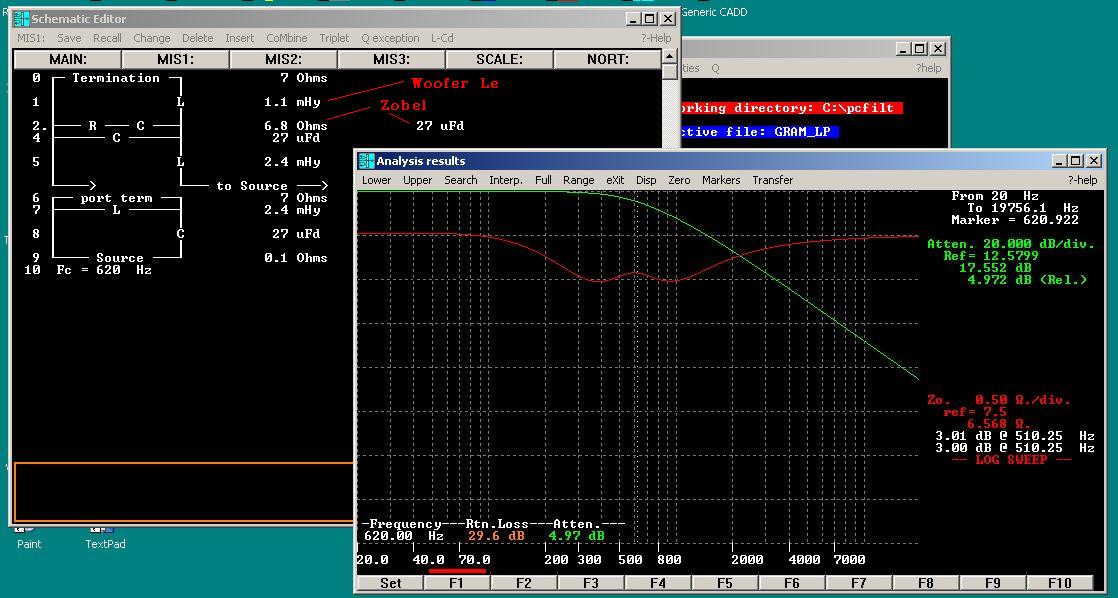
Gram, If you have the equipment to measure the Zo you can optimize the values for the best Zo on your speaker for the area of the crossover. You need to investigate you setup to verify that you are including the inductive component. The simple voltage plot through a series resistor doens't give you the complete picture. Even though I shut the "return loss" display off when I made the plots, I actually used return loss to do the optimization. Return loss includes the complete complex impedance. It's directly related to VSWR. The simple Zo can look worse even when the return loss is better. It looks like your already have it a lot better than most designers will wind up with it though! Al K. UPDATE: I just looked at the return loss to optimize it right at 620 Hz. It looks like 22 uF is actually better then 27 uF. The difference is small though.
-
Gram, I'll let Gil explain his numbers. I didn't follow his post carefully as I trust what he says. I'm sure he's right. The 27 uF + 6.8 Ohms was done by computer optimization. The 6.8 ohms is simply the closest standard value to the design impedance of 7 Ohms. The 27 uF happens to do the best of tuning out the Le over the widest frequency range. I have seen the formula for Zobel networks and it works pretty well, but this method nails it! Al K
-
Gram, I simply did a sample design that might do what you need. It's a 2nd order Butterworth (12 dB / octave). The 1.1 mHy is the woofer Le. the Zobel of 6.8 Ohms and 27 uF NonPoler electrolytic The main elements are 27 uFd polypropylene and 2.4 mHy. The element values are the same in the highpass and lowpass which is normal for N=2 Butterworth. The crossover is roughly 620 Hz. The computer design is below, BUT: the plot shows 6 dB / octave steeper slope than you will get becasue the analysis is assuming the Le (1.1 mHy) is part of the filter. It's NOT! It's part of the woofer driver. Al K.
-
Gram, OOPS! I didn't realize you were in India! So much for telephone idea. If you plan to go with Butterworth you are definitely stuck with whatever output inductor the computer program gives you! There is really no advantage to Butterworth. It's just going to limit your flexibility. Could you try again to reword what is confusing you. Having nearly 35 years designing L-C filters makes it difficult for me to understand the thinking of a new-comer to the field. I take too may very basic things for granted. Al k.
-
Gram, It looks like we are not on the same page! Maybe it would be best if you gave me a call on the phone (410 546-5573). Text communication leaves a bit to be desired! Al K.
-
Gram, I think you are getting the idea except that there is no need to subtract Le and L1 (actually Ln in filter jargon). As it happens, when you design a Chebyshev filter, the parts values change dramatically with the level of passband ripple you select. For a woofer filter, ripple as high as 2 dB is fine. Your listening room is far worse that that! This means you can select a passband ripple such that the output inductor becomes EXACTLY EQUAL to the measured Le at the crossover frequency. If you do this, the output inductor is totally GONE!The only time you need to subtract the two is in the case where the inductor required for the filter is larger than the Le. That turned out to be the case for my ES400 network. In that case you just add an inductor to the output to make up the difference. The program I provided for download has the ability to keep inputting different ripple values to manually zero in on the correct value to make the inductor equal to Le. That is, a manual iteration. If you choose to use a Zobel to absorb the Le, then you can do virtually anything you like with the ripple value and even go even order. Al k.
-
Gil, The question about the effect of the series inductance of the voice coil on the skirt is one that fooled me too. I needed to do a series of experiments to see if N=3 when the output element was the voice coil inductance performed as N=2 or N=3. By measuring the acoustic output of a woofer with no network, storing it in the analyzer's memory and later subtracting that plot from a similar plot with the network in the circuit, it was obvious that the filter was performing as N=2, NOT N=3. The reactance slope seen at the input of the filter was that of N=3 however. I still have these plots if you would care to see them. I posted the entire research on the Audio Karma forums about 2 years ago. You might want to dig them up if you are a member over there. Al K.
-
Gram, You will never be able to terminate the filter in exactly the correct impedance over the entire frequency range the woofer will operate. You need to design it for the impedance that will best terminate the filter in the most critical area. That is where the filtering function "comes together". That is right in the area of the crossover. The general rule of thumb is an error of 1.5 :1 or less. This is considered acceptable. For a 7 Ohm design you can get away anything from 4.7 to 10.5 Ohms. In the microwave industry this is referred to as "return loss" and represents about 14 dB return loss. 1.5:1 is also "VSWR", a term you are probably familiar with. Al K.
-
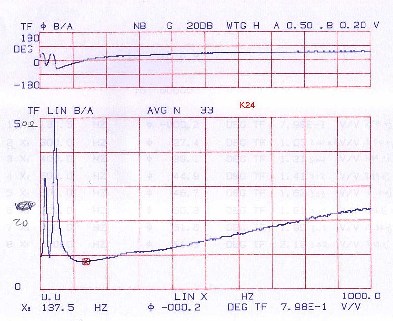
Lee, I could be wrong, but I betcha that won't show you the reactive (phase angle) of the woofer impedance. It's a factor that loudspeaker people just don't even consider. Below is the sort of plot you really need. It is for the Klipsch K24 driver (Heresy II). The marker is at 137.5 Hz. This is the ONLY frequency where that driver is a resistive impedance and it's 7.98 Ohms. Every frequency higher looks like an inductor in series with a resistance. You need the reactive component in order to properly design the Zobel or to compensate for the Le by absorbing it into the filter output inductor. --- UPDATE --- Lee informed me by email that the software he suggests DOES indeed have the Zo and phase capability. I downloaded the demo for it and, a first glance seems to say that he is right! It needs some sort of USB tests leads to work that I don't have, so I can't test it out to be sure though.