Erik Mandaville
-
Posts
4571 -
Joined
-
Last visited
Content Type
Forums
Events
Gallery
Everything posted by Erik Mandaville
-
Dean: I don't know why I was thinking that there was a dedicated tweeter as part of the equation. It seems that a single series resistor would probably be best. You could use something like a single pole, six position switch for this. The crossover in the HF branch is of course before the attenuator (resistor or group of resistors), and would be connected to the single pole (contact in the center of most rotary type switches), with each output postion of the switch connected to one end of each of the resistors. I was looking at the board you made (again, very clean work), and there is space for a few more, with the same kind of layout. In other words, a total of even 6 resistors, maybe. So, with the crossover connected to the pole on the switch, and one end of each resistor connected to one of the positions on the switch, the other ends of those resistors can be joined at a single common point. From that common point, run a single lead to the positive connection for the driver. Even though the resistors share this common node, there will only be a single resistor in the circuit at a given time, so you can just reach back to the board and switch from one to the other easily. You could use, say a group consisting of 1.5ohms, 2ohms, 2.5ohms, 3ohms, 3.5ohms, and 4ohms, and that way get just slightly more flexibility in terms of what might sound the best. There probably won't be a big difference in the half-ohm steps, but maybe enough for slightly finer adjustment. The resistors can be practically touching to save space, and oriented just as the existing two are right now. 25watt jobs! Or put them anywhere on the board that works. A piece of angle aluminum can be used to mount the switch, with two holes drilled where it connects to the board for greater stability than just a single hole. The other part is of course drilled for the shaft of the switch. If you did this, a shorting type switch might be a good idea. For the ends of the resistors, use a couple of 3 position solder terminal strips or just a barrier strip, and run a lead from each resistor connection point over to the corresponding position on the switch. I've been able to get 18AWG solid wire through the little holes on the switch positions, but they can't take too much more than that. 18AWG should be fine. 20AWG would work. You don't even have to crimp the daylights (aka crap) out of the connection on the switch, just push through the hole and quick touch with solder. Erik
-
I thought they were marvelous when I heard them. Maybe I'll buy a pair one of these years. People have said in the past that they are insanely priced. I disagree. Erik
-
You can also just add a switch to toggle back and forth between the resistors -- you could include odd values, too. Switches just make things a little easier. I think I would be inclined to use a parallel element across the driver after the series resistor, but the open-mindedness concerning this kind of attenuation is, for me, admittedly refreshing. The autoformer will be an interesting experiment, and you can install a switch for that as well. Erik
-
"Hey, what's up?!" "I went out for some groceries this morning and guess what I found at a church garage sale on my way home?" Mint condition Heresy1s in blemish-free walnut veneer. $15.00 for the pair. Lucky Dog! Erik
-
Dean: Setting that up to compare would be interesting, and at the same time I understand about the time involvement to do that -- not to mention extra cost for parts. And in the end, might not be worth the hassle if what you've got is sounding good as it is. Monster coils in there! They sort of caught me by surprise this early a.m. Erik
-
[:$] ....I'm interested in both a squeezebox AND a popcorn maker. Actually, I shouldn't be embarassed about that. A good popcorn might be kind of fun for movie watching! I have no idea of how to even hookup or use a squeezebox, but they sound kind of interesting to me.
-
Mark: I think I remember reading about that in the past. The Black Gates are nice electrolyitics, the torpedo-sized 100uf power supply version pretty expensive, but good. I used Black Gates in cathode bias resistor bypass positions. I also remember being scolded by someone years ago because I even dared to use 220uf in an input stage bypass, but it was actually very good sounding. I took the bypass caps out of my Moth amp to see what it would sound like, and it was horrible, no sparkle at all. I'm using 470uf. Anyway, thanks for the clarification. Regarding Dean's networks: I would honestly and genuinely be interested in what the same network would be like using an autoformer. I'm not sure of the order of slope used in the midrange (is this two-way or three driver jubilee?), and obviously, one can't simply switch out L-pad resistor/s for an autoformer without compensating for the change in load impedance, but does anyone know if experiments were done with this? Maybe it would be worth a try. Al's ES networks are very high order passive networks, but, if I'm not mistaken, still incorporate the autoformer for squawker attenuation. Erik
-
What was Mark's modification to the D45? Are you referring to the 50 volt caps in the power supply? Nice networks. The hovering resistors look like they might be non-inductive wire wounds. Erik
-
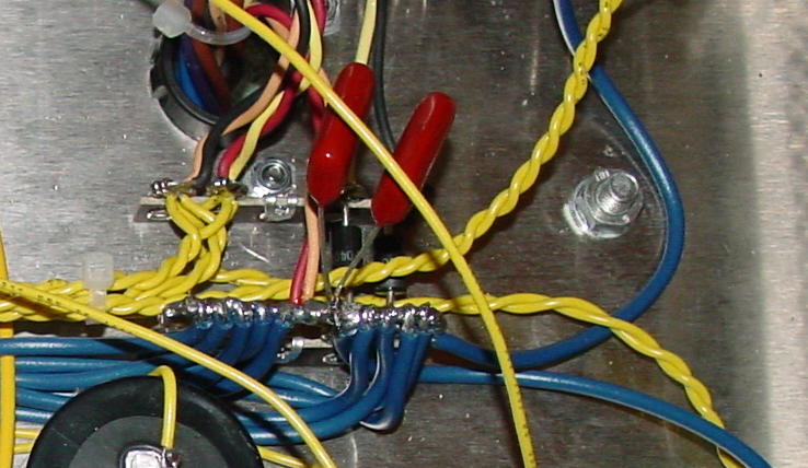
I mentioned a small filter on the AC high voltage secondary, and the following picture indicates that. Note the two high voltage film caps connected between the AC side to the star ground.

-
"The foams also rot on the Bose 901 speakers over time and it's expensive to have the surrounds redone by a speaker repair place because it has 18 drivers (9 each speaker) to re-foam surrounds. The much earlier Bose 901 (1960's) used cloth surrounds and those don't rot if well taken care of." I looked, but I don't remember. Do the new Bose drivers still use foam surrounds? Our Lowthers (just the drivers cost about $500 more than the complete 901 system) use foam surrounds, and they are still in perfect shape after 10 years. Erik
-
"One thing I've learned over the past 40 years or so of audio insanity is that there is, someplace in the world, a room and a system that will make any given pair of speakers sound magical and wonderful and beautiful, no matter how good/bad those same speakers might sound just about anyplace else." This is so true. And what if that someplace in the world happened to be your own listening room and the speaker happened to be the Bose 901? There are those on this forum who have at first really disliked the sound of the Hertiage line, and then became 'broken-in' (sorry, I'm of the view that people rather than components are what most often get broken in during 'break in') to their unique sound. It would be kind of neat, I think, if one's impression of the reproduction of music were devoid of associations with brands of capacitors, resistors, vacuum tubes, and everything else. I admit there have been times in the past where I was a little shocked about what it was that I was actually listening to (meaning cost v.s. performance). Based on what I had gone through back home to get the best sound I could, maybe even a little disappointed. So. Bose blows, and I was once blown away. Our listening area is probably not very well suited to the 901, but in the right place, with the right equipment, and in front of the person who happens to like them, they are probably just as good to that man/woman/girl/boy as the Klipschorns are to me. You know, there may be Bose groups just like there are Klipsch tribes that invite friends over to laugh at the La Scala PA speaker compared to the 901. Or, maybe they don't worry about that at all and just enjoy what they have. LOL! Sorry, that's an amusing thought to me -- turning the table around. I was a La Scala owner, by the way, and they sounded so good to me on the day I sold them that I almost regret it. They were easier to deal with at times than the Klipschorns. Erik
-
Mark: I would have actually done the same as you regarding the voltage tolerance of those caps. I was just pointing out that there have been times in the past where capacitors I was using in power supplies were operating for years at very near their max rating without any problems or failure. On that ground connection: There are a few power supplies in the past I've seen where that common node was intentional as a way of sort of balancing out the voltage between the two capacitors. What I remembered later about those was that I think there were very high values of resistance in a circuit associated with that connection that maintained the advantage of the doubled power rating of the series connected capacitors. My dad confirmed that, as well. He said he's seen this on some sort of test equipment (or some such 'thing') he made. You are right on the capacitor relationship/connection, and I stand totaly corrected on that. I wanted to respond to the picture you posted of the integrated line filter on one of your components. That is exacty one of the devices I was referring to in the post above. Suppression takes place immediately -- a point the other contributor to this (I can't remember his name right at this moment) made as well. However, even if the XTi doesn't have EMI/RFI/transient filters on the AC supply, there are still things people can do to take care of the problem -- if there is a problem. It doesn't have to be a 'throw your hand's up in the air' and quit sort of syndrome. Erik
-
"I replaced them with high quality 50V caps just to be safe in case there WAS a power surge while I was using the amp." Obviously didn't 'hurt' to do that. However, those series-connected capacitors comprised essentially a single cap that, as shown in the helpful schematic of the PSU, wasn't even seeing half of its rated voltage. It's obvious Crown knew what it was doing. Erik
-
Moreover: As far as the filter section goes off the full-wave bridge, would it not be a correct assumption, considering that you have two capacitors in series with one another that are in parallel with the load, that the effective working voltage of that combination will provide double that of each single capacitor? Obviously the value of capacitance would be cut in half, but since the concern mentioned above had to do with the robustness of the power supply, maybe there is not such a cause of concern with respect to that aspect of the design. It also seems there has been some effort to equalize the voltage between the two capacitors. Erik
-
"Power surges and ground bounce transients usually do more damage passing through a power stage to components beyond than damage to the power supply itself. Spikes and switching transients create energy up in the 1-2 mhz range and are best filtered by RFI/EMI suppression where power enters the equipment before it is rectified. Once this HF energy gets into any equipment, all bets are off as to damage, with CMOS devices being the most sensitive to this sort of damage, other SS devices right behind. Crown has EMI filtration on the XTI's power input." Good point, although bets don't necessarily have to be off. If Crown doesn't install RFI/EMI filters on the AC input into the component, it is in fact possible to do that if one has access to the Hot, Neutral, and Ground legs of the AC line. The same can also be done on the high voltage secondary before it's rectified -- meaning on the AC rather than DC side. Simple brute force line filters can be made, the chokes for which quite easily wound by hand, and for more severe cases of overload, MOVs can be installed across the power transformer primary. I use them on all the amplifiers I've made. That Crown uses such suppression devices on the input is really not so uncommon; and depending on individual levels of present RFI/EMI, can be helpful -- they have for me in the past. I've also had reasonably good quality ripple filter capacitors run just under their rated working voltages for years without problems. Having some head room is of course never a bad thing; I'm just saying I haven't had problems due to overload of the kind/tolerance mentioned above. For those who don't have this kind of electronic working ability, which would almost certainly void any warranty, there are an assortment of devices available that can be used. Erik
-
John: If I send you a great little doorstop I have, will you send me your PP amp? Kidding aside, I think push-pull can sound incredible, too. Erik
-
Inductors for Heresy I's tweeter & squawker?
Erik Mandaville replied to kg4guy's topic in Technical/Restorations
1) I almost invariably connect the tweeter directly to the input -- something which has been tested and yields essentially the same crossover frequency as its more common association with the autoformer. The reason for that has in part to do with the similarity in net capacitance between 13uf and 2uf in series (for the original factory connection on the top of the autoformer), and using a value of 2uf as the filter to the tweeter connected directly to the input. Capacitors can equal that difference in just their tolerance specifications alone. I suggested a direct tweeter connection to the input to Al many posts ago, and still have his response to that. It was actually an interesting and constructive discussion. 2) I actually got rather reasonable performance from this network. I'm sure you're right though. Thanks - Erik IB Slammin: You're welcome. -
Inductors for Heresy I's tweeter & squawker?
Erik Mandaville replied to kg4guy's topic in Technical/Restorations
It was modified to test a switching device to toggle back and forth between different setting on the autoformer. It was no different than going to the trouble of doing it manually, either by desoldering or by way of solderless connectors -- both of which are archaic and difficult. Up to that point there had not been any effort made toward switched tap settings, and this worked fine. I have preferred to build the bandpass differently, which is reflected above, the one for which I wound my own coils. I'm really not sure what a doozy is as the term is applied to a crossover network, but if you want to elaborate concerning this or the other one I made, that would be fine. The same approach in the doozy network can be used with different values of fixed resistance, which would be my preference. I don't care for the autoformer. Erik -
edit: Apologies -- please see Garage sale forum. I completely forgot about that. Erik
-
Inductors for Heresy I's tweeter & squawker?
Erik Mandaville replied to kg4guy's topic in Technical/Restorations
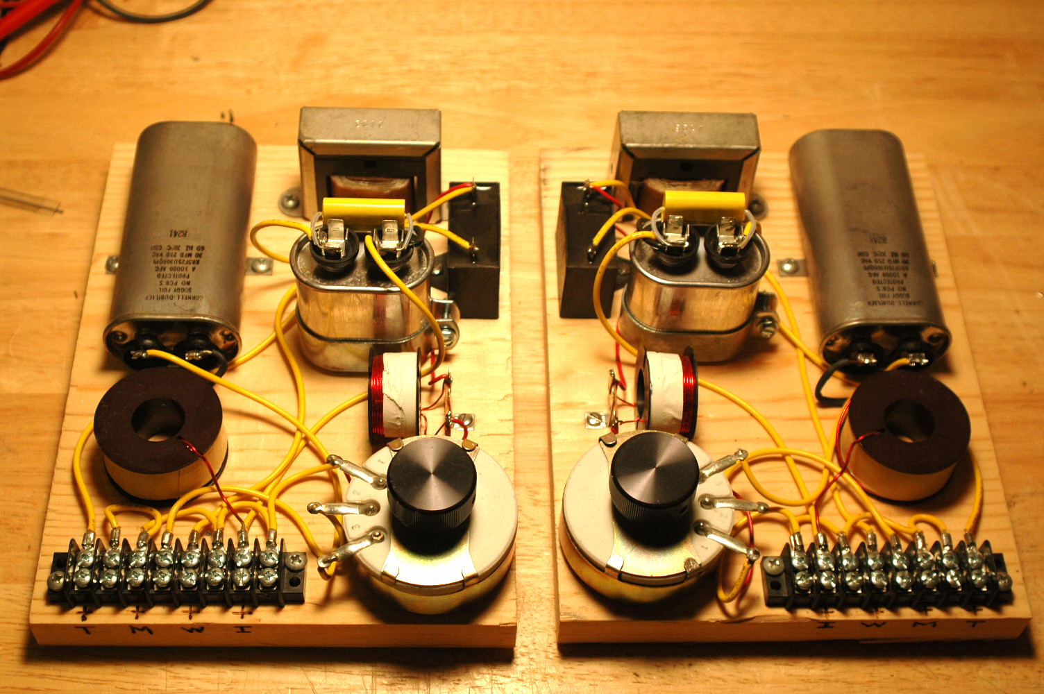
And here is a sort of combination of both -- a kind of variable-fixed. Some had commented on the difficulty of changing the amount of reduction on the midrange, which requires a fair amount of work, and, depending on how it's done, a change in value of capacitance. This is a type 'A' network that uses a 3-position switch to enable switching on the fly between three different levels of attenuation on the autoformer. The switch box is kind of hard to see, but it's connected to the long leads that have been laced. This actually worked just fine. Despite the increased flexibility, the actual steps of attenuation are fixed. This was also posted above. slight correction: This is the type 'A' with Bob Crites series inductor modification included with the crossover point 4.5kHz. The swamping resistor is in place to offset impedance variations, which would normally require changes in value of the capacitor in series between the autoformer and input to the crossover.
-
[]
-
Inductors for Heresy I's tweeter & squawker?
Erik Mandaville replied to kg4guy's topic in Technical/Restorations
As opposed to a Variable type: This is a traditional 12/dB/octave Butterworth network I made a few years ago for our Klipschorns.
-
Inductors for Heresy I's tweeter & squawker?
Erik Mandaville replied to kg4guy's topic in Technical/Restorations
Fixed L-pad detail:
-
Inductors for Heresy I's tweeter & squawker?
Erik Mandaville replied to kg4guy's topic in Technical/Restorations
"I gots ta ask. What is a fixed L-Pad? Makes me think of........ jumbo shrimp." Sure: A fixed L-pad consists of a set value of resistance in the form of a resistor -- like 25 ohms, 40 ohms, and so forth. The autoformer on the older Heritage networks also uses fixed, individual steps of attenuation, but goes about the process of attenuation differently. Each tap is essentially a fixed step in attenuation, but what changes is the reflected impedance load seen by the amplifier rather than simple resistance. A variable (as opposed to fixed) L-pad operates much like a volume control, which is why it's referred to as variable. It's continuously variable in that the user is able to dial in the exact amount of attenuation needed/wanted and then stop. See the picture below? The two white rectangular components on the left, literally in the shape of an upper-case letter 'L' together form a 'fixed' amount of attenuation for the squawker. They perform the same function as the autoformer. I had used them in the past on other systems I built, but never on the Klipschorns. With both the A and AA designs, I preferred the resistors, which doesn't mean they are inherently better -- just that it's what I prefer. It's possible to also use a single resistor in series, which is still a fixed value. Erik
-
Wonderful job, Erland! Out of curiosity, what are you using as your starground on the chassis? I see the negative leads from the filter capacitors connection to a common point, and was just wondering how you accomplished your circuit ground connection. Again, very nice! Erik