

John Warren
-
Posts
2262 -
Joined
-
Last visited
-
Days Won
1
Content Type
Forums
Events
Gallery
Posts posted by John Warren
-
-
22 hours ago, EpicKlipschFan said:
looks brand new
Have the original HP shipping carton, plastic wrapping and service manual too. It just didn't work. Does now.
My ULD signal generator shown above developed a problem, sent it back to SRS for repair yesterday, it's still under warranty. I have another ULD unit but the SRS is insanely low distortion.
-
24 minutes ago, Crankysoldermeister said:
“Loudspeaker people don’t understand how crossovers work.” -ALK
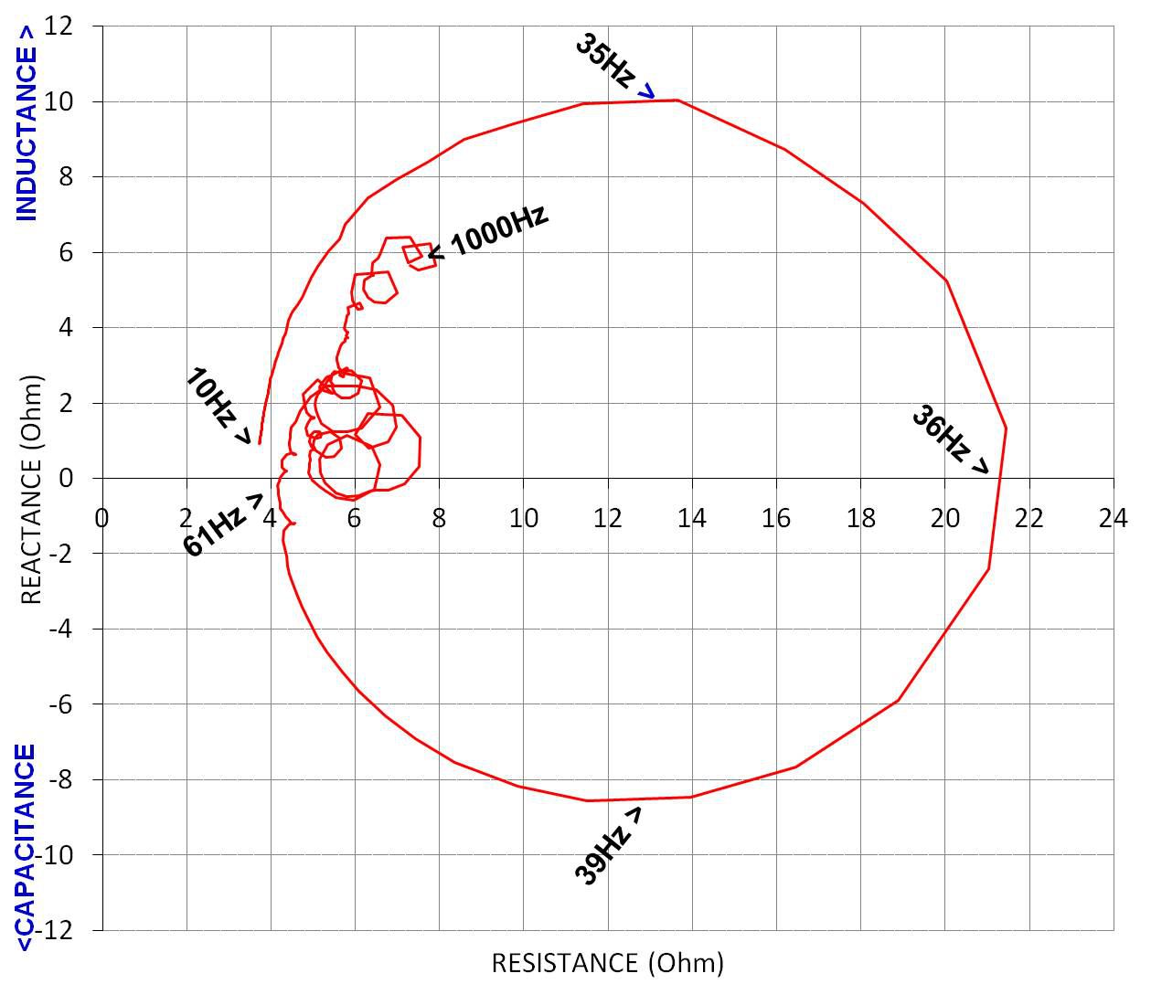
Here's the Z of the Klipschorn bass unit (alone) measured by yours truly some years ago. The plot starts at 10Hz and ends at 1kHz.

Below is Heyser's plot from the Audio magazine review article where he measured the 3-way system and plotted the result. The loop in the middle is the bass section, similar to what's shown above.
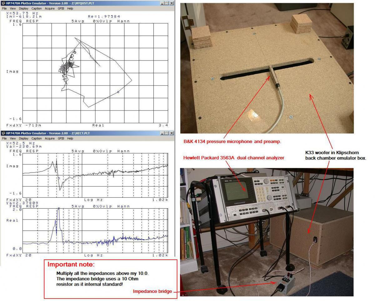
Here's the alk plot using his Klipschorn "emulator".
Here's the contraption.
-
 1
1
-
-
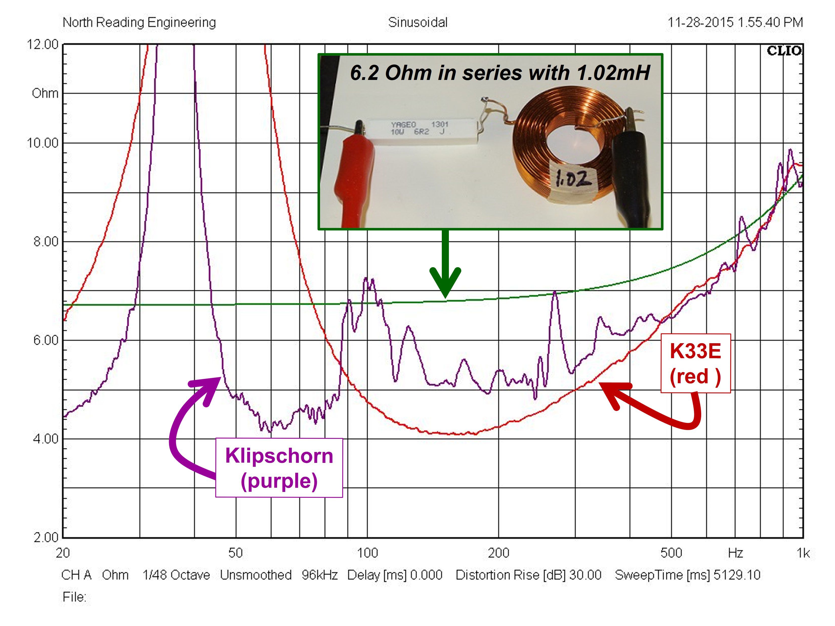
On 5/31/2022 at 9:58 AM, bribassguy said:
The AP12-xx series networks are designed to operate with the Klipsch K33 woofer which represents an impedance of 6 Ohms in series with 1 mHy voice coil inductance.
Really?
-
1
-
-
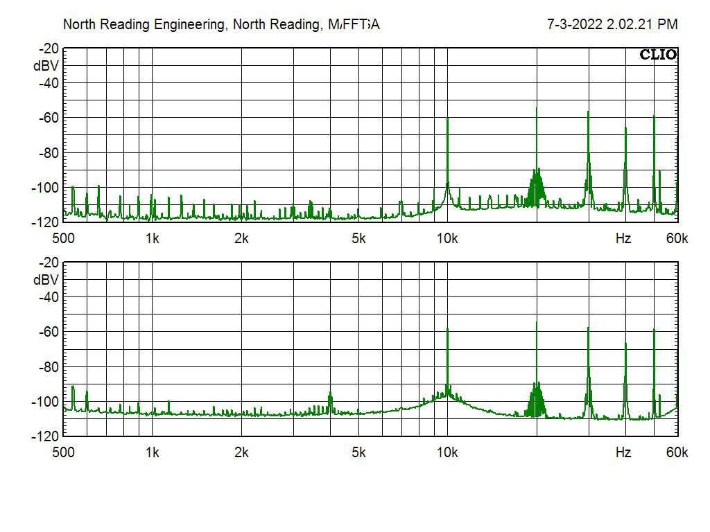
Both the 333A and the Krohn-Hite output the residuals of the signal being measured. The output of each is shown below taken between 500Hz to 60kHz, the bottom plot is the 333A. First thing to note is that they're similar, a good thing. The fundamental is 10kHz, attenuated to -60dBV by each instrument leaving the harmonics and whatever else is left to measure. At this testing extreme, the Crown D-75 exhibits some instabilities at 20kHz, the second harmonic. The amp gets hot as hell testing at high frequencies and it's not a mystery that thermal distress will show up in the residual spectrum.
-
 1
1
-
-
Here the analyzer is measuring a Crown D-75. Input is a balanced, 10kHz, 0.5Vrms sinewave from an ultra-low distortion source (<0.001%). Output from the amplifier is measured across an 8 Ohm power resistor. The gain is set to realize 10Vrms across the resistor. The amp stewed for about 30minutes before measurement. Testing at 10kHz will drive the amp to get very warm to the touch.
The 333A is reporting 0.042% THD+N (0.1% FS, pointer a bit to the right of 0.04%).
The signal is simultaneously fed to the Krohn-Hite 6900B analyzer that has a current calibration sticker (performed at Krohn-Hite, NIST traceable). The 6900B is reporting 0.046%THD+N indicating the 333A is a bit off from the actual magnitude.
-
 1
1
-
-
On 6/22/2022 at 6:08 PM, Budman said:
AL @ ALK ENG is RETIRED
it's spelled RETARDED.
-
1
-
-
Did a complete overhaul on this 333A. New Al- and Ta-electrolytics, many new transistors. The goal was to achieve like new performance. I have many of the HP special BJTs including the Germaniums from this era.
The 333A and 334A were popular distortion analyzers from 1968 to about 1980. They're actually very useful for measuring THD+N in tube amps but good luck trying to find one in good working order. They're straightforward to rework but getting the best out of them isn't so simple.
The key to getting these units to operating "like new" is the voltmeter circuit, it must measure accurately to the micro-Volts level and that's not so straightforward.
How does the analyzer work? A signal is applied to an amplifier to be tested for distortion, say a 1000Hz sine wave signal (the fundamental). The amplified signal is then sent to the analyzer where the operator "tunes" a Wien bridge to "notch out" the fundamental leaving the harmonics and noise for measurement by the meter circuit. The accuracy of the analyzer is governed by the accuracy of the voltmeter and the accuracy of the meter circuit over the bandwidth of the instrument (5Hz to 600kHz).
Below is the signal source, a 100uV, 400Hz sinewave signal which requires specialized instruments to source.
And the measurement of the 100uV sinewave at the 333A is below. The meter range knob (lower right) is set at .0003 which is 300uV or about 1/3 of a millivolt at full scale. The magnitude of the voltage is read at the 0-3 graduated scale. Note the pointer is at 1 (= 100uV).
The 333A and 334A units are useful to about 0.03% THD+N which is about 30X higher than current state of the art units, like the Krohn-Hite shown above which is capable of 0.001% THD+N.
-
2
-
1
-
-
The build "quality" on the Crimson thing was absolutely, decided garbage.
Why would anyone give these clowns a penny?
-
2
-
-
1 hour ago, Curious_George said:
The 12SC7 is a 12SL7GT with a "special shield" to reduce hum according to tube data documentation. A 12SL7GT could be used as a direct repalcement. I've never needed a special shield when using 12 or 6SL7GT's in an audio circuit.
GT=glass tube.
-
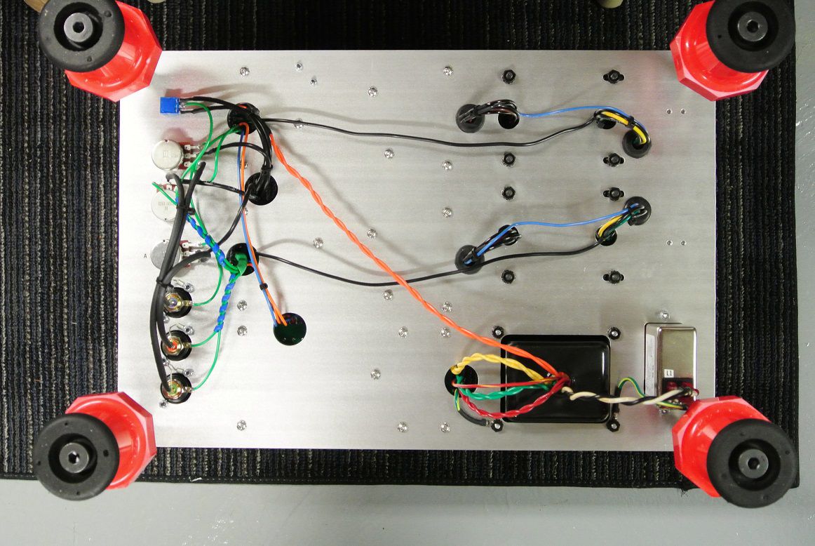
On 5/1/2022 at 9:03 AM, Marvel said:
I sort of agree, but this was designed to pretty much be a drop in replacement for the original board, so connections to the board were made to follow the original placement of wiring.
That has virtually no impact to the layout.
-
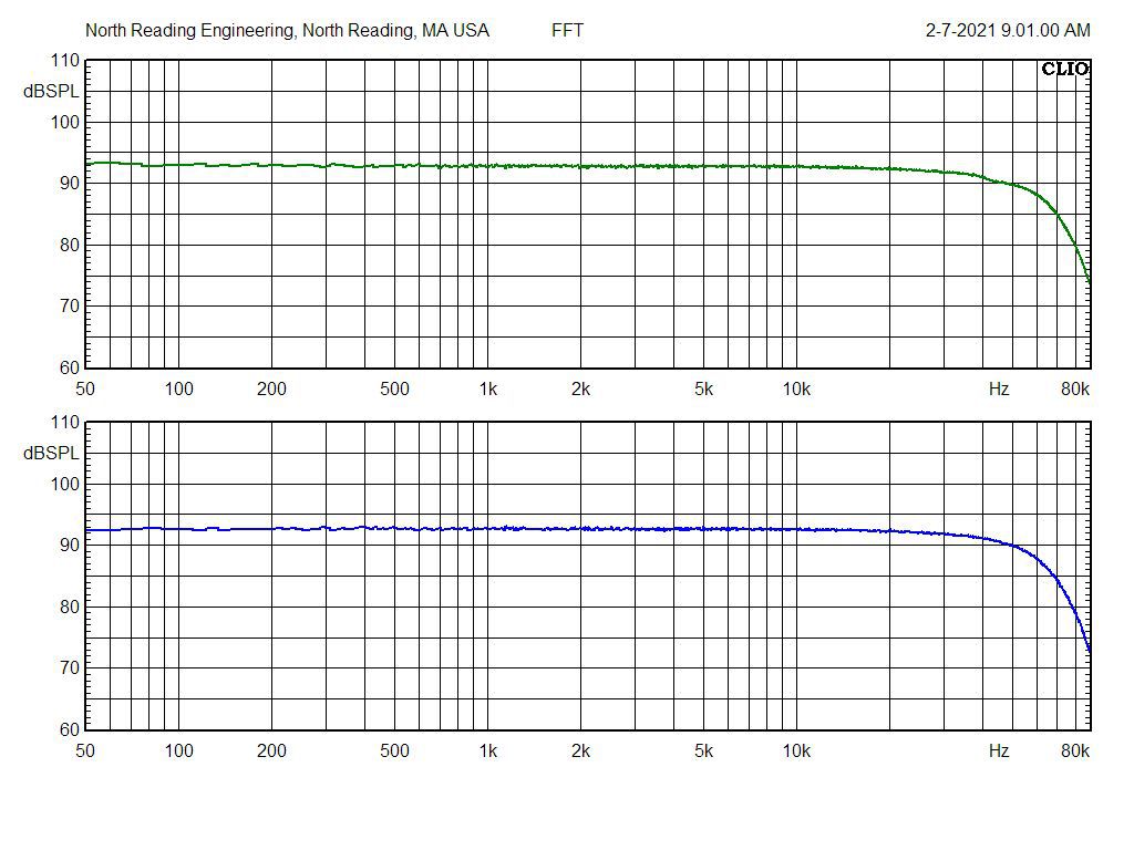
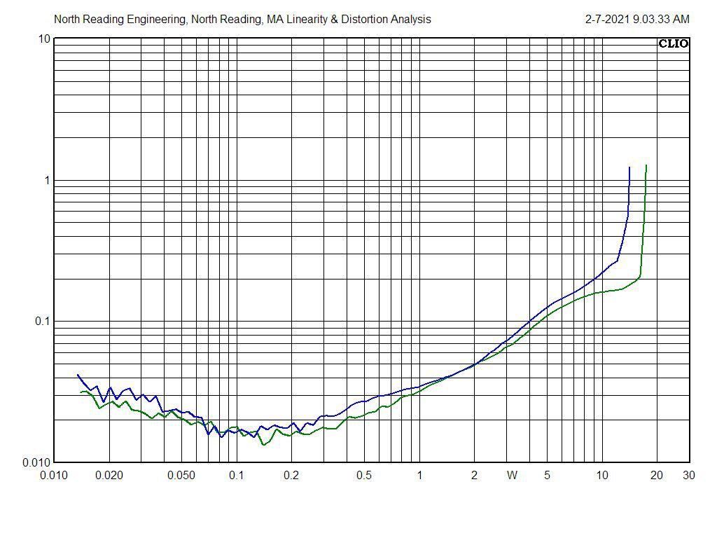
Here's a project I did a year ago. The measurements are the most basic, 1kHz THD and bandwidth. Without even listening to it, I'd state it will sound pretty good. But, do the measurements tell the whole story? No.
Swapping the 5AR4 rectifier for a solid-state plug in improves the low end a bit which I don't need a plot to tell me, I can hear it. I can however measure the difference in 20Hz distortion and the temperature of two resistors. The hotter resistors mean output tube life will be lowered. A compromise I'm not willing to take. Why? Because the amp, as is, satisfies everything I look to a tube amp to satisfy.
-
3
-
-
The tube crisis is manufactured. JJ can easily supply the current demand. For those that are in need, you're being played.
JJ is shipping but $ are still x3 what they were this time last year. Wait.
-
2
-
-
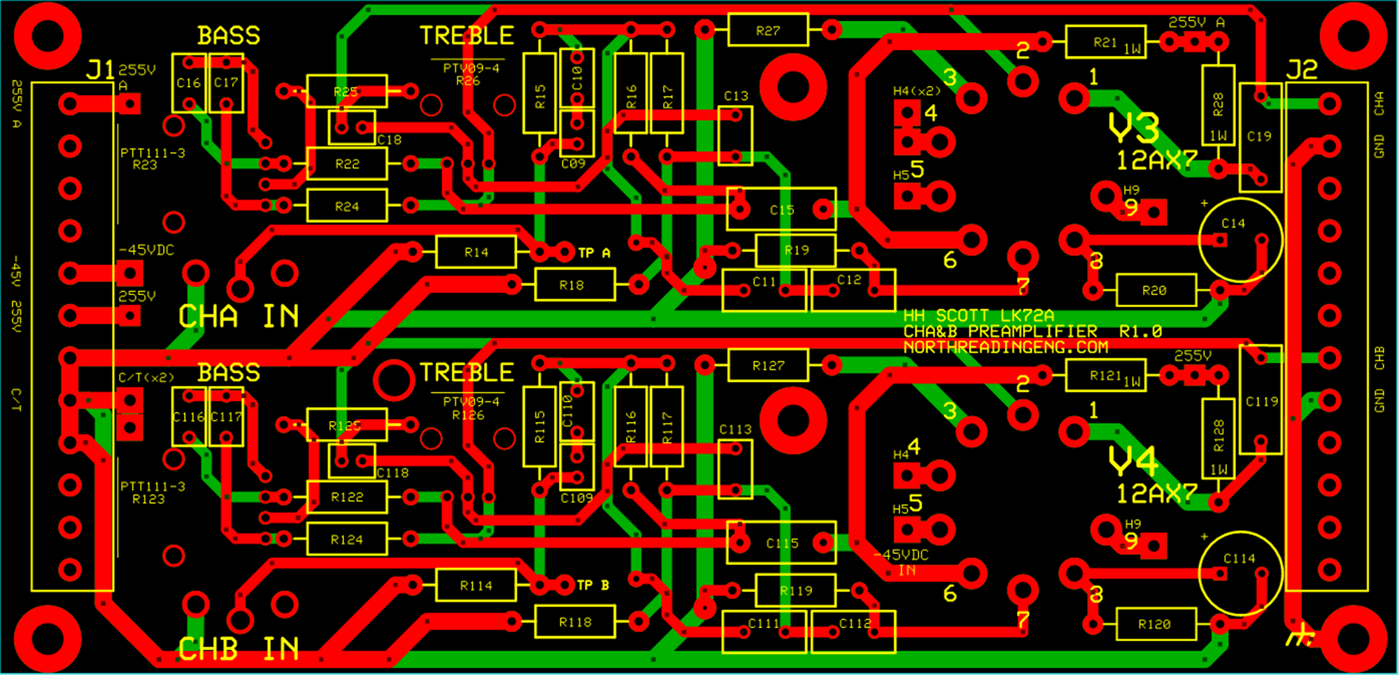
The PC board layout was done by newbie.

-
Then there's the price point. How much would one be willing to spend on a match pair of, say 7591s? 80USD? My guess is the new WE will come in closer to 300USD. So 600USD for your Scott 299C.
I was ready to pull the trigger on a new amp build based on the Citation II. That will not happen. Anyone interested in buying a tube amp should think long and hard about that purchase, you might be stuck waiting for 2 or 3 years before your EL34s or KT88s are readily available.
-
36 minutes ago, BadChile said:
Good news is EHX claims to have resolved the export issue, bad news is there are additional costs on both the export and the import end, as such, expect price increases.
https://www.guitarworld.com/news/electro-harmonix-tube-supply-resolved
In 2019 a J&J 7591 was $16. In June they'll be $125 each.
Good luck with that bros!
-
He doesn't do much on anything.
-
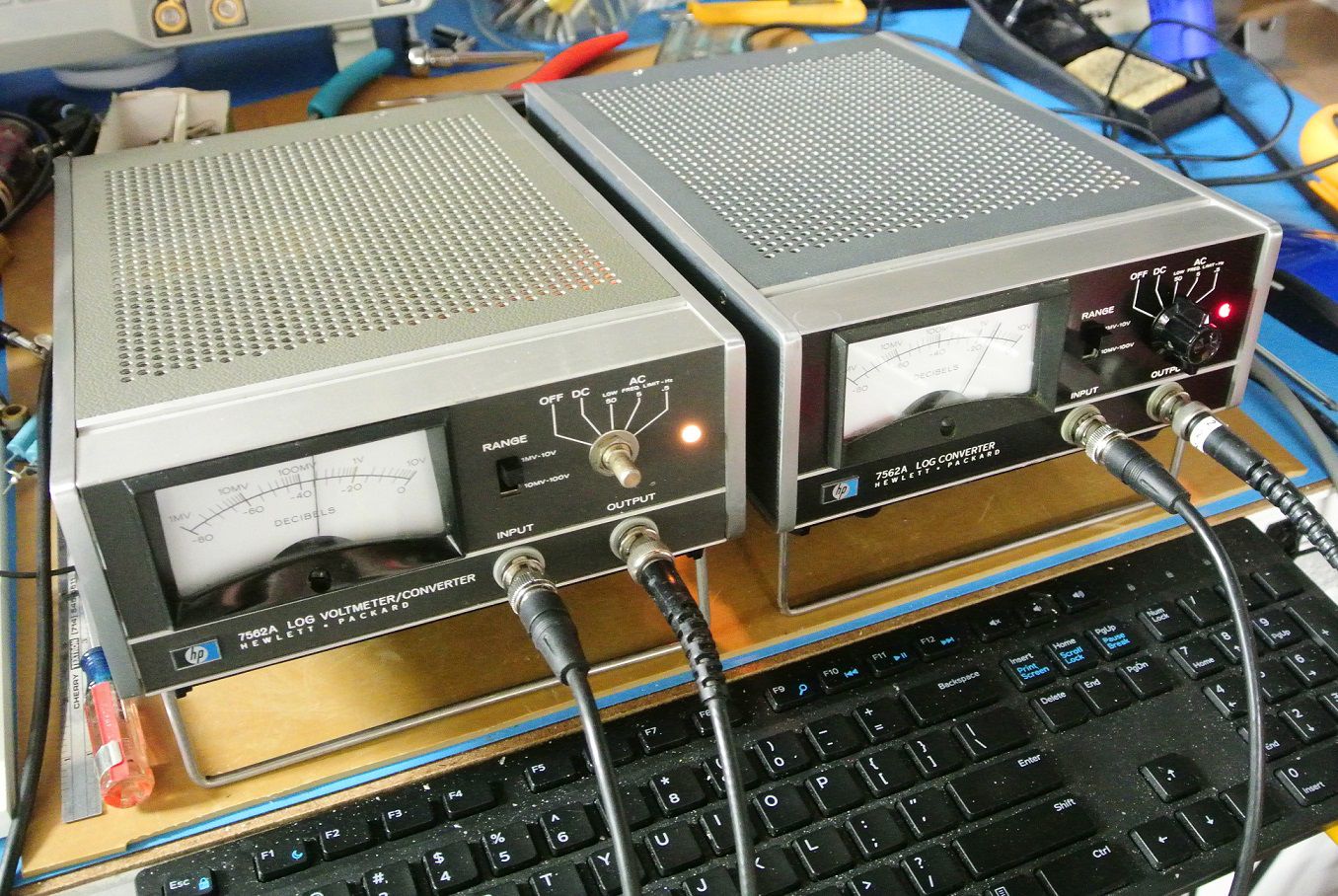
I had one and managed to score a second. They express voltage on a log scale allowing 5 decades to be captured on the swing of the needle pointer. Useful to measure voltage across a load resistor for amplifiers under test. The right unit is the first issue, 1968, all gold traces. The left unit is the last year of manufacture, 1976, Pb-Sn traces. That unit also needs a knob, which I found on-line and ordered!
Measures both VAC and VDC from 1mV to 100V and dB equivalents.
-
2
-
1
-
-
Losing djk was a big hit to the local audio community in general. I miss his contributions here and elsewhere.
-
6
-
1
-
-
It's a statement amplifier: Carver has decided the vast majority of buyers are too stupid to know better.
-
1
-
1
-
-
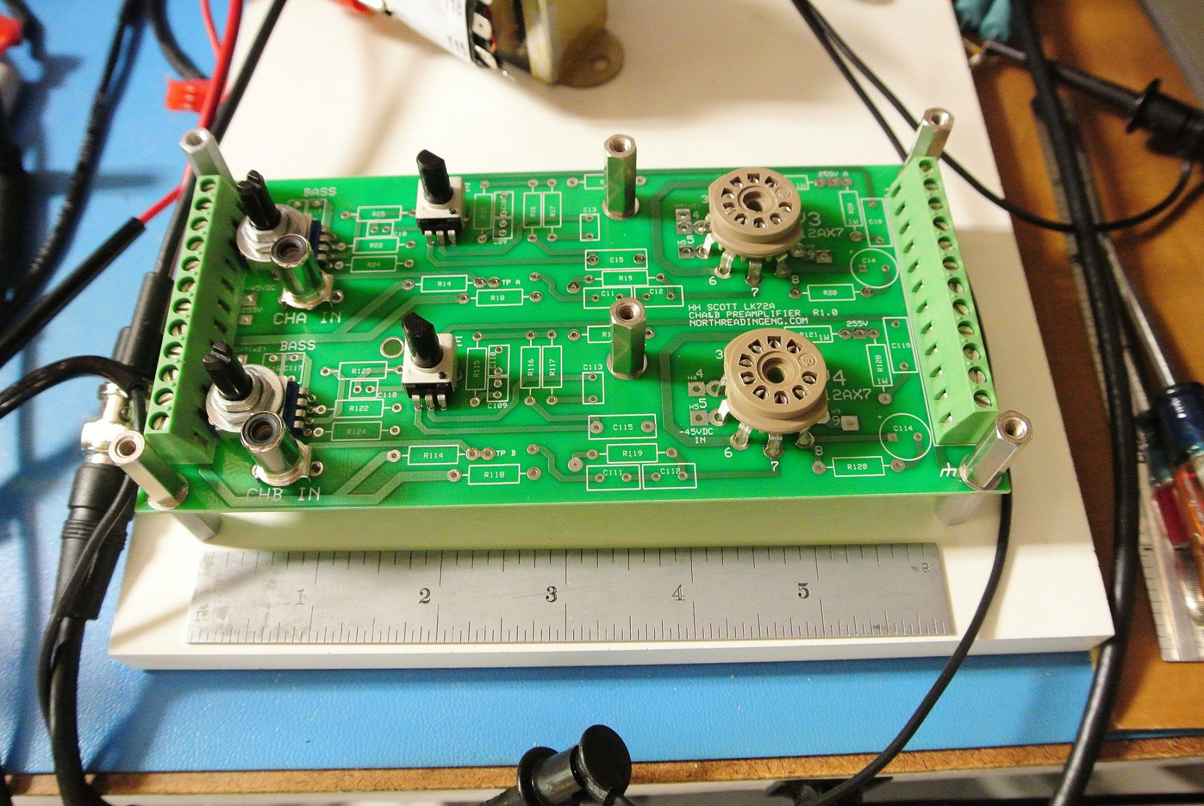
Boards came in a bit earlier than expected.
Checking first that the pc board hardware can be installed.
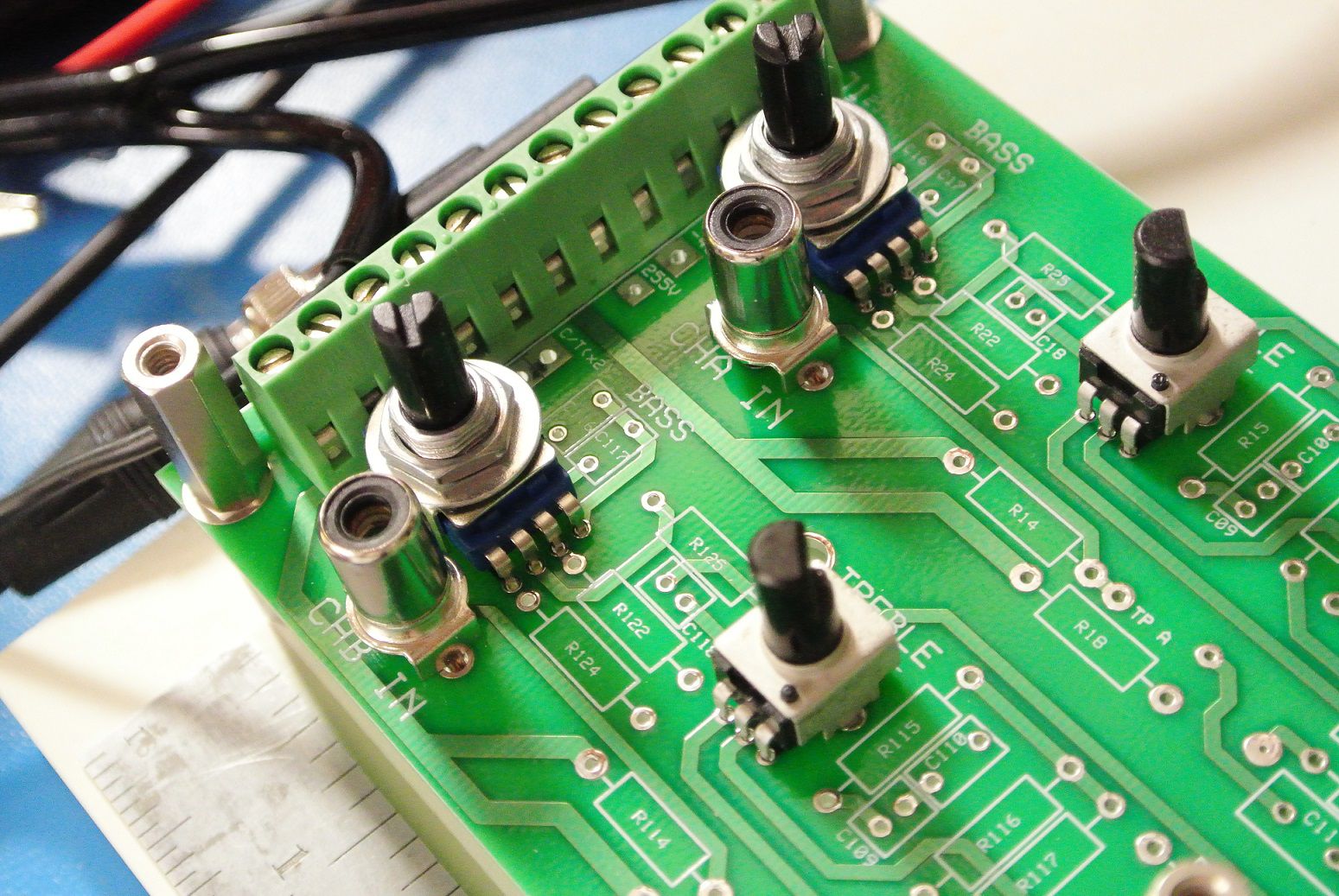
Bass and treble pots. I'll start a separate thread on the preamp. Board mounted RCA terminals as inputs.
-
1
-
-
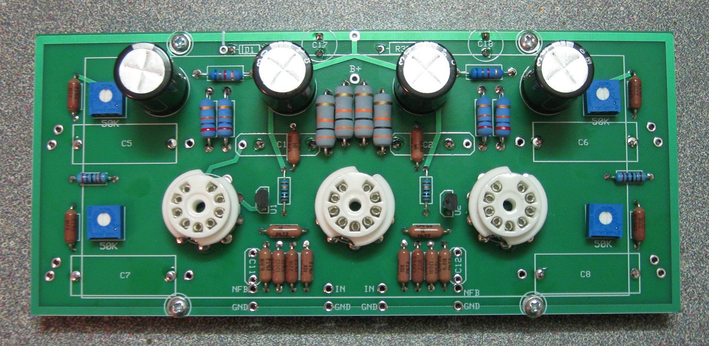
15 hours ago, mark1101 said:
Is the circuit the Scott LK-72 preamp circuit or modified?
It's bone stock with added traces to probe the behavior. There will likely be a few components that differ from the OEM configuration to accommodate for any instabilities that might occur. Those are flushed out on at test.
The board contains two independent channels with bass and treble pots. A log taper level adjust will be on the chassis. No additional mode selectors will be considered but the board allow for then to be added.
Also, I used the same component IDs on the board as is on the OEM schematic so you can follow along at home!
-
Yes. I've wanted to get this going for some time. The boards are due in on the 19th from the supplier. Takes a morning to assemble then test!
-
10 hours ago, captainbeefheart said:
You can of course measure the screen current
-
Let's break out a 12AX7 preamp board from the LK72 schematic. I managed to squeeze both channels including bass and treble potentiometers on a 2-layer, 6.6x3.18" board (the max size allowable before incurring a much higher fabrication cost).
Requires two inputs: 255VDC (anode) and -45VDC for filament heaters.
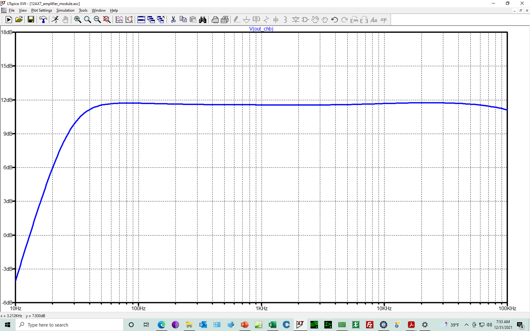
Simulated bandwidth using LTSPICE. Input will be adjusted using external audio taper potentiometer.


HP 333A Analyzer
in Solid State
Posted
Not modified but wasn't working when I got it, so fixed it.