ounvme
-
Posts
33 -
Joined
-
Last visited
Content Type
Forums
Events
Gallery
Everything posted by ounvme
-
Jan Olav Landa I saw your pictures on the AV forums can you list me the numbers on the parts that I have pointed. I cannot read them in your pictures. Many Thanks
-
The amplifiers are almost never manufactured by Klipsch anymore it is worth asking but I doubt that a dealer would have component level schematics. Engineers and integrators would be more of a promissing route. Worst case is I have to wait until a broken one shows up on ebay
-
Someone surely has one of these that is willing to have a peek inside. Plus it benefits us all because then I can make a full schematic for future reference as I have done before.
-
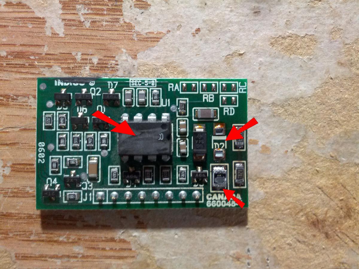
I have an RT-10d that has suffered from a power supply failure. I have repaired many klipsch amps and unfortunatley they all have the same issues. This however does not stop me from enjoying them and it makes them easier to repair. The RT-10 has suffered from a failure in the power supply control board. This is refered to as the PDC board in many other designs. I have noticed that a diode has "blown" off the board and there is a resistor that has fried. These seem to be the only issues I could find. The problem is that I cannor identify the parts to repair as I could not find the diode and the resistor is so badly burnt it is not readable. I come to ask for your help. Can someone identify these parts for me or provide a picture or the part numbers. The main chip has also been sanded off to prevent identification. A sub in this price range should be repairable not throw away or "refurbishable" These parts will cost less than $5. Please see the pic below: Thank You

-
D12 would be a diode. Those all-in one boards are a total pain to work on.
-
I really would have to look at it but I would ballpark it around $60 including parts. I always estimate first.
-
The board uses all the origional components with the addition of 2 100R reesistors and the 2 heat sinks. The PCB is the expensive part at $50, but it is in my opinion a big improvement. If you want to use it for 240V other parts will need to be purchased. The current restriction is that it must be a 600142 REV 3 board. The other boards use a different sized transformer or they are all-in-one boards. They can also be updated, but I have not designed a circuit board replacement for them yet. If you are looking to repair the amp cheap I would say try it yourself. With shipping it would be around $100 if I did it. I will list some steps and instructions.
-
I attempt repairs on the OEM amps if you are willing to send it out. Success rate depends on the damage but usually 80%.
-
I have seen many of these amplifiers broken and needing repair. The usual problem is the mosfets in the power supply die. The problem is the way the board was made you usually ruin it trying to replace them. The heatsink is also garbage and the layout in general leaves much to be desired. This is typical of BASH board. I like to repair these amps for fun and try to bring them back to life so Klipsch lovers can once again enjoy their subs or the DIY community can use a Klipsch amp. For this repair I found that the entire power side of the circuit board can be modified upgraded and replaced. I have optomized the location of the components and tests have proven the design to be good. The mosfets have improved individual heatsinks and the PDC board is out of the way with some breathing room. The mosfets are also turned around so if they happen to blow they are not at risk of damaging the transformer. The current version works only with the US version at 120V. 600142 rev 3
-
I am trying to isolate a problem and repair a Sub-12 amp. The sub makes a popping/clicking/electrical sound a few seconds after it "warms up" I measured the secondary supply voltage and I am getting 100V. This seems high as alot of Klipsch products run on 50-60V. I cannot confirm that this is the right voltage. The sounds/noise is supply related but I am having trouble finding the cause. It could be the Bash Module(Controls the boost converter for the secondary supply) or the PDC Board (Controls the SMPS switching). Even with the noise and powered on I was not getting any output from the sub. The best way to describe the noise is like a zipper being undone slowly 15-20Hz. Anyone have any tips? Sending back or replacing isn't fixing the problem its an expensive bandaid. This is a fixable issue. I am just stuck where to start.
-
If you still have the old amp I could use it for parts if your willing.
-
I recently developed a nasty rattle on my RW-10. I inspected the driver the wires and the amp and all are secure and in good order. After closer inspection the rattle is coming from the front panel of the box. The box appears top be built with a groove for the front panel to slide into and then the inner seams glued with a small bead. This seems like a very very poor design. I can slide a playing card almost all the way around the panel where the glue has seperated. Since the panel is held in with a tongue/groove I cannot remove it to properly re-glue it in place. I could re-glue the seams but it will probably not hold or last too long. If I glue it I want the full seam glued as well as the tongue/groove. (The way it should have been from the factory) Screws are not a good option as there isnt much to screw into. The only other solution is to build a new box with the proper dimensions and better construction. Any Ideas please help. This is an upsetting problem to have and not a great reflection on the construction/quality. Especially after having to replace the plate amp previously.
-
Unfortunatley I do not have any schematics. Klipsch doesnt seem to like to release any of that information. I however in my spare time have started to create some schematics by tracing the circuits on some of the amps I have worked on. Currently I am working on a RW-10. This is a time consuming process and takes alot of attention to detail. If your amp is suffering from the fuse blowing problem I will have a look at it if you are ok with shipping it.
-
I have repaired a few of these bash amps. If you are willing to USPS me the plate amp only, I will repair it and post some pictures of the process for a a few bucks. 90% of the time its an easy fix. The other 10% its hit or miss.
-
I have decided to make a full schematic and layout of this power supply and see if maybe I can build myself a replacement. It is more fun to me to design and create something vs shelling out cash for something that will break in a year anyways. I am sure this good info to have saved somewhere anyways seeing as Klipsch is stingy with schematics for us DIY types.[:@] I started with the PDC board 660038RA. R1 - 200K R2 - 1K R3 - 392 R4 - 750 R5 - 750 R6 - 392 R7 - 750 R8 - 750 R9 - 200K R10 - 200K (4/5) (7/8) (9/10) are in parallel to obtain desired values. C1 - R1C 472 KCS 605 (4700pF 60V 5% ????? ) C2 - 3300pF 5% 100V C3 - 3300pF 5% 100V D1 - 1N3070 D2 - 1N3070 D3 - 1N5245B D4 - 1N5245B D5 - 1N4148 D6 - DIAC (UNKNOWN VALUE) Q1 - MPS A92
-
After some research the what I thought to be a burnt diode is actually a DIAC an AC diode. Essencially 2 diodes in reversed polarity. I am going to look under a microscope to see if it has any markings as to the value. It has also been confirmed that the DSP 104 is a NTC Current Limiting Inrush Thermistor 10ohms 4A
-
I've been workin on trying to fix a couple of out of warranty subs and running into the same problem over and over. My RW-10 fried and I have a Sub-12 with the same problem. The IRF740 fets were blown on both. While trying to figure out what is the cause of this one thing I notice is that both have a blown diode on the PDC board and both have failed DSP 104's. Unfortunatley I can't find any info on these components. Can a tech or anyone specify what the DSP 104 is and the proper direction and type of the diode on the PDC board. The silk screen is double marked. I am gonna throw out a theory that the DSP 104 is failing first and causing the fets to blow. It could be the other way around but either way they both need to be replaced. Any input is appreciated. Have a look at the picture. The blown diode is in the upper right corner and is all black. One of the diodes was removed to inspect the damage to the board.
-
I am refering to the green thing. Yes it could be a thermistor. I'll have to try and find out what kind it is and see if i can find the origional value.
-
I have an RW-10 that took a dive. The small breakout PDC board has some cooked diodes. Is the schematic available for this model. I believe it is not in production. D11/D12 and the proper install directions are needed. Thanks
-
After some close inspection I also noticed this. R400 has a nice crack on both sides. I havent seen a radial resistor like this and can't find any info on the value of it. DSP 104 doesn't return anything relevant when searched. It measures 15ohms but I am assuming that is not correct since the component is cracked. Have a look...
-
I am also pretty sure that the power to this sub stays in a standby mode until a signal is sent to the ribbon cable. That switch on the back that goes between auto/on im sure is somehow tied in with the power supply. For now I am going to try to make a complete schematic of the power supply and figure out how this thing actually works. It may help with figuring out why the fets are blowing and why it will not power on. The ribbon cable has a voltage output for the opamps that power the crossover so we should be getting voltages there too in the 12-15v range.
-
Chances are that the transformer is OK. After taking mine apart all the wires seemed to be in good condition. I did take data on all the windings so hopefully I can wind a replacement. I shouldn't have taken it apart but now I know for sure that was not the problem. Pin 1 does not have any connection it is connected to a copper strip in the middle of the transformer and most likley some sort of feedback to the control circuit. I was in the same boat being able to apply power but no output. If possible can you check those diodes on the breakout board for me?
-
I also removed the main transformer to check for shorts. Pin 1 is marked by the white dot on the side. Pin 1 has a wire connected but does not seem to make a connection to any other pin. Pins (2 3 4) & (5 6 7) measure connected. This is the input side of the transformer. On the output side Pins (8 9) (10 11 12) (13 14). Transformer pins up 7-o o-14 6-o o-13 5-o o-12 4-o o-11 3-o o-10 2-o o-9 1-o o-8 It appears that some of the windings are center tapped but I think something is wrong since pin 1 reads no connection to any other pin. The input side of the transformer may be cooked. If someone can also verify that. I may try to rewind it if its shot.
-
Well unfortunatley the power supply in the sub took a turn for the worse again. I don't really know what happened but the outer IRF740 blew again and one of the diodes on the board behind the mosfets fried. I am thinking it could be the dreaded death of the SMPS transformer. I did find something fairly interesting. There is an error in the silk screen on the little control board. See the picture below. D11 is double marked. I am pretty sure that both diodes are IN4148 types but would like verification of type and the correct direction of D11
-
I am sure this is an all to common problem with alot of powered subs. I have repaired a few sets of promedia subs and usually they follow the same trend as well. When these amps wont power on 9 out of 10 times its power supply related. The resistors are heavily loaded and run hot, same with the mosfets. When blowing fuses or not getting power into the sub, I always do 3 things. (1) Check the diodes. (2) Check the resistors. (3) Check the mosfets. Usually one of these will be blown or bad causing all the problems. When testing my RW-10 I found that Q402 which is an IRF740 mosfet was fully shorted. This was causing my sub to blow fuses and not have power. $6 later I replaced both Q402 and Q401 and the sub is singing happily again. I am going to list the values of the parts that would most likley blow and the values here for future refrence. The smaller resistors showed no sign of heating or wear and all the color bands were clearly visible so I left those un-measured. Q401 - IRF740 Q402 - IRF740 Q200 - IRF540 D200 - MUR1520 R203 - .1 5% 3W R210 - .1 5% 3W R204 - .1 5% 3W R206 - 100 5% 2W UNREADABLE DIDNT WANNA LIFT FROM BOARD 2W (1) 470 5% by C414 (3) 10 5%