


billybobg
-
Posts
250 -
Joined
-
Last visited
Content Type
Forums
Events
Gallery
Posts posted by billybobg
-
-
Dayzed,
Very nice. I like the finished look of the wood. ... Oh, yeah, the woofers are impressive, too.
-
So I PM what I promised to the OP and do I hear ANYTHING back??? I dunno with people these days. [8-)]
-
Islander,
Thanks for the kudo. I do see single Belles occasionally, and quite frankly I've thought since the build that perhaps a Belle could have worked with a bit smaller screen build. Belles are beautiful.
-
Thanks IKF,
I will be adding a sub, so all should be good. Thanks again,
bbg
-
Olorin,
Frankly, I didn't take your question as criticism. Only curiousity. I think that's what keeps forums going. I've shared what I know and questions are to be expected. I'm just being honest. Fact is, I've got the math skills to figure out, just didn't think that it would affect the LF enough to matter. As IKF stated, we live in the mid regions. The LF tends to be geared towards efficiency and again, this seems totally up to the job. Anyway, I really do appreciate the comments I've received and I do like playing around. It would have been a real bummer had I, like you said, found it totally unacceptable after several weekends of work.
bob
-
-
At the risk of criticism from all sides I'll confess my sins. I kept the 3" and the sides of the straight part of the base bin (about 7"). The slope at the rear did change and I had it run from the opening of the base bin to the side of the base bin. The flare is what it is. I can't quote the source, but in researching I found that the extra flare at the front would not affect the response as much as keeping the volume of the base bin consistant with the original. I'm willing to accept inputs (stone throwing) should anything not bare out, but I'm very satisfied with what I hear.YMMV. If I had the equipment, I would make measurements, Now that you've mentioned it, I probably should do the calcs and see if anything I did is fatal.
-
I have to admit that I don't know what you mean by "spacing".
-
I tried to load other photos, but I'm having some trouble. Anyway, you see the difference in heighth.
bob
-
-
IndyKipschFan,
Ya hafta wait until I get home. Unfortunately, I didn't do build photos, but then there are plenty of those. I do have a photo of the three fronts which I'll post when I get on my home 'puter. I have some sketchy (as in questionable in accuracy) Sketchup drawings and a calc sheet on the inner dimensions of the base bin if anybody is interested. This includes calcs on the angle of the W front.
bob
-
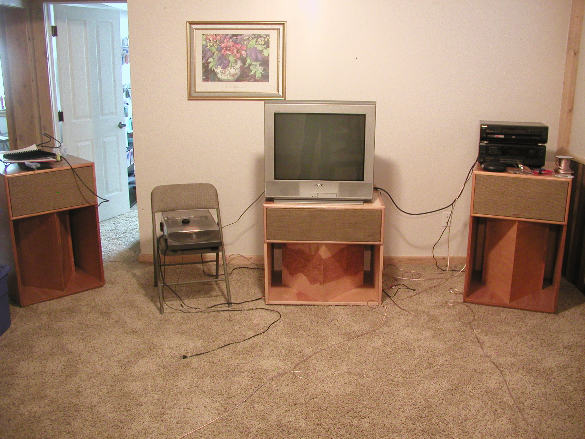
I built what I call a squatting Lascala. I picked up a used AA Crossover, K-77, and K-55 driver. I bought a woofer from Crites and a 401 Horn from Klipsch. I was able to reduce the heighth down to 26 - 27 inches which will work for the screen I'm building (115"). I made the woofer box wider to keep the volume near the production model and mounted the K-77 to the side of the 401. The heighth of the base bin is constrained by the 15" woofer. I made it 16". I also took some heighth off the HF section with mounting the K-77 to the side. There is room for a second tweeter, but the advice I got from the forum is that there could be comb filtering effects with having two tweeters so close. I can't tell the difference in sound from my ca. 1981 LaScalas and this new build and the trio is very impressive with any movie, though I've only watch some samples so far on an older tube tv.
bob
-
I agree with the 3/8" radius. I matched up a bit, but then there was no marking on it[:^)] I believe it was my 3/8" bit. If it doesn't work out, you can always make it larger.
-
I'll lay my bits up against mine tonight if you'ld like. My memory is always foggy on stuff like this, but I think its 3/4". Then again, that may have been what they ended up after being knocked around and sanded.
-
I think this is what Greg is referring to: http://www.woodworkersjournal.com/Main/Public/Articles/Skill_Builder_Miter_Joints_5554.aspx
-
Dave
Okay, I took a GOOD look at my LS last night. Quite frankly, the grain of the veneer is VERY random. It looks a lot like it came from the sap wood of the tree and therefore is really not very good grain. I have to backtrack and confess that, if anything, all of the grain of the speaker is running N/S. [:$] Oh, well. Serves me right for commenting based on my feeble memory . My only saving grace is that I have looked at a lot of speaker updates that matched the grain pattern going around the speaker. Some looked good, some not. On my squatting LS for my center channel, I attempted to match as best as I could. Turned out okay, but not a show piece.
Anyway, your work definitely worth watching and should be superior..
bob
-
Excellent. My BB do not run that way. Interesting[^o)]
Keep up the good work and I look forward to your pics as you proceed.
-
I appreciate the work you're putting into the speakers. I'm wondering if it was a conscious choice to thave the veneer on top running north/south as opposed to east/west.
-
This company has veneer that is paper backed and its relatively easy to apply if you have ANY skills.
-
Have you tried: http://www.klipsch.com/na-en/support/ ?
-
http://www.klipsch.com/na-en/support/
Just ask. Klipsch is reasonable for parts they stock so even if they don't cover it you'll be okay.
-
Mike,
Just getting to know you and my initial thoughts echo everyone elses as to you as person. Congrats on everything..
bob
-
-
I don't know about that generalizing. A voltage source with an output resistor is a current source.
Okay, I'm an idiot trying to answer this.
Ohms Law: V= I x R. Power out is P= VxI. Remember that the current source is a voltage source with a resistor in line. For the whole circuit then Ohms Law looks like V= Ix(R1 +RL) R1 equal to limiting resistor and RL equal to the load such as an 8Ohm speaker. If R1 is large (10 times or more) compared to RL, then mathmatically, RL can be ignored I=V/R. This means that the current delivered is independant of RL (as long as RL stays low).
For a voltage source, its sort of the opposite. In the real world the voltage source is low impedance (Internal.25 ohms or so) so the majority of the voltage drops across the load and therefore the load pretty much sees what voltage is being produced at the source. Think of a car battery and that the voltage is independant from the load.
Put both of these in the power equation P=VxI and sustituting V=IxR, you get P= (IxI)xR (Current Source), or substitute I=V/R and you get P=(VxV)/R (Voltage Source)
What does this mean? My impression is that it indicates how the output power is calculated. A current source can be limited to protect the load with the source resistor. With a voltage source, a diode could limit the voltage that is allowed across a load.

Corner radius on Commercial cabinets
in Klipsch Pro Audio
Posted
Are you searching for Klipsch handles or using generic? Just wondering.