tube fanatic
-
Posts
2978 -
Joined
Content Type
Forums
Events
Gallery
Everything posted by tube fanatic
-
The ESE is my overall favorite xfmr and I have often used it even when one of the smaller members of the series would have been enough. The FSE and GSE are terrific for the higher plate current applications. How large is the chassis you are using to be able to accommodate the xfmrs underneath? Maynard
-
 When doing comparisons, if the levels are not matched with extreme accuracy it is impossible to draw a valid conclusion. Most listeners will pick the slightly louder of the two. Maynard
 -
The question in my mind after reading this discussion is what constitutes “optimal sound.” Sure, amps can be designed with incredible specs such as minuscule distortion and phase shift, but will they be universally accepted as sounding better than units with lesser credentials? Not in my experience. I know guys who much prefer the sound of certain amps with certain speakers, neither of which have great specs, because they find it most pleasing. There are folks who actually like SETs with, in some cases, high 2nd harmonic distortion over those with a minimal amount (the original Darling 1626 amp comes to mind as an example of the former). Put a solid state amp in the system with immeasurable distortion and other sound influencing factors and they run out of the room. In my opinion, while it is always worth striving for amazing measured results, it may not always be worth the effort if the end user doesn’t like the sound. Maynard
-
Actually, I consider it better to use a little more solder than not enough. As far as the “3 second rule,” it was used at the power supply company when training new workers who had never soldered before. Heat the joint, flow the solder, keep the iron on the joint for 3 seconds. They taught it that way to avoid cold solder joints. My method is different and has been cultivated over the past 66 years. I was originally taught by old timer ham operators whose work was exemplary. More on that some other time! Maynard
-
Your method is equally effective since the object is solely to prevent the insulation from being cut. An issue often encountered in 75-80+ year old radios is xfmr leads pulled across ungrommeted holes. As the leads dried out with age, the insulation split. Even some vintage audio amps have had a similar issue. Maynard
-
Prospective builders should take note of Henry’s use of grommets through which the power xfmr leads pass. Costing only a few cents, this step will prevent a sharp edge of the hole from cutting into the insulation of a lead causing a possible short. Maynard
-
Well, Henry, your chassis work sure puts mine to shame! Keep up the beautiful work. Maynard
-
I typically use metal film resistors in new builds for their usual 1% tolerance. However, as Henry stated, it really is not necessary for values to be that close in an audio amplifier. A change in value of even 10% should not be a problem. Tube to tube tolerance differences are far more likely to cause an audible difference. Given how much enjoyment audiophiles derive from their vintage gear, which is generally loaded with carbon comp resistors, I don’t have any problem using them if needed. Years ago I acquired a load of circa 1950 Allen-Bradleys from the son of a former Bell Labs engineer. In spite of their being old (like me!), most are within 5% of their specified value and work just fine in anything in which they are installed. In vintage audio gear which I restore, they allow the appearance to remain as it was originally which some prefer. I don’t find them to be any more noisy than anything else. Gassy tubes are much more likely to cause issues. Maynard
-
Some questions have come up about R1/C1 at the input to the Sweetie. I termed it the “ear bleed filter” after hearing complaints from a guy that many modern recordings contain so much high frequency boost that they make his ears “bleed!” The components form an adjustable low pass filter which allows the high frequencies to be attenuated to suit listening preferences. It is quite useful and is standard in all of my builds. I initially included a bypass switch which allowed its total removal from the circuit, but no one used that feature so the switch was eliminated. Eventually, I may have to head south so Henry and I can sit on the porch in rockers as he suggested. For now, on the very rare occasions that my wife gets me to stop working and relax, I sit at the old unused railroad station with other old farts and watch the freight trains go by……… Maynard

-
There are different methodologies which builders use when constructing pairs of mono amps whether they are on one or two chassis. Henry mentioned that he will build one channel at a time. Another method, which I use, is to construct both simultaneously by performing the same operation on each before moving on. For example, I would install the input and output jacks on each before continuing. Same for the ground bus, filament wiring, and so on. Doing that allows for both units, or channels, to look identical in terms of lead dress, and component orientation. My OCD necessitates having near perfect symmetry 😊. When I worked at the power supply company I was surprised that a similar technique was employed when a large number of units was ordered. For example, we would lay out 25 front panels on the bench, and then go from one to the next performing the same operation. There too, it allowed for each one to look virtually identical to the next. The boss of the section in which the 7 foot tall monsters were constructed had even worse OCD than me to the point that he insisted that the cable ties on the wiring harnesses be spaced exactly the same! His units were true works of art. Maynard
-
I don’t have the schematic handy, but it should be the driver screen bypass cap. Like the cathode bypass cap, it is used to put the screen at ground potential for the AC signal voltages. That is the simple explanation. Maynard
-
Although I have designed many well accepted single ended pentode amps, I still favor SET operation if having the choice. While you can certainly get a great deal more power from the 6Y6 in pentode mode, it is not outstanding in my experience. Other tubes sound better to me. As for ultralinear operation, I have never liked the way it sounds having tried it with a few different tubes. I haven’t encountered many situations in which increasing the power from around 1 watt to 3+ watts was worthwhile. As you know, I have been involved with flea power amps for quite some time and, with Klipsch speakers, power output in the tens of milliwatts is often more than enough. It has always been fun to let someone hear an amp without telling them its power output capability. They often don’t believe me when I reveal it! Maynard
-
No need to use zinc chromate before painting? Maynard
-
This can turn into a very long, detailed, thread so Henry can decide if it should be separated from this one. Some of the points have been made already, so I will add some more: 1) thermal agitation- the irregular, random, motion of free electrons can produce minute currents which are greatly amplified by the driver stage (which, depending on the design, can amplify by a factor of even 100 or more). This will pass through and can be heard at the speaker. The higher the temperature, the more noise which is quite relevant considering the hot cathode of a tube. And, the electron flow through solder joints, volume controls, and components may, if at the input of the driver stage, be amplified and become audible. 2) shot effect- small irregularities in plate current due to individual electrons striking the plate is often encountered in high gain stages (I.e. the driver) and may be audible at the speaker. 3) microphonics- caused by mechanical vibration of tube elements causing variations in audio currents. Tubes are notorious for this, but it can be noted from capacitors as well. 4) hum- often attributable to AC operated filaments is often a problem in driver stages. Proper cathode bypassing and filament lead dress can minimize, but may not eliminate, this issue. If the B+ supply to the driver has too much ripple (AC component), it will be passed through and will be audible. 5) stray electromagnetic fields from other devices, routers, lamp dimmers, etc. may find their way into high gain driver stages and become audible. So, you can appreciate that elimination of the driver stage of an amp and going directly into the output stage, which has vastly lower gain, will result in a much cleaner sound. I need to get back to work, so others can discuss the coupling cap (or lack of) situation. As far as the SS ramifications, I guess that should be a topic in that section as opposed to here. Maynard
-
No question that the least number of powered devices in the signal path, the better. Even more revealing is directly driving the power amplifier stage with the source. Only one amplifying device in the path between the source and speaker produces some amazing results. This has been confirmed by folks who built a Little Millie or Little Sweet Potato (the LSP has been updated since the original was posted). Maynard
-
I have the impression that there are many who want to build their own tube amp but find the chassis layout and prep to be too daunting a task. And, with layout being critical for a good result, this is quite understandable. Back in the day, the obvious solution was to go with Heathkit whose instruction manuals were without equal. If you could solder decently you could be assured of a successfully built piece of equipment. Well, there is a modern company here in PA which has emulated Heathkit. Analog Ethos offers amp kits at very fair prices all of which should interface very well with your Klipsch speakers. Their instruction manuals can be downloaded from their site so you can see for yourself the incredible detail and why it will be difficult to make any mistakes. And, you will be taught how amps work as you go through the build! Take some time to look at their offerings and feel free to post any questions about the amps here. I, Henry, and others will be glad to help out. https://www.analogethos.com/diytubekit Maynard
-
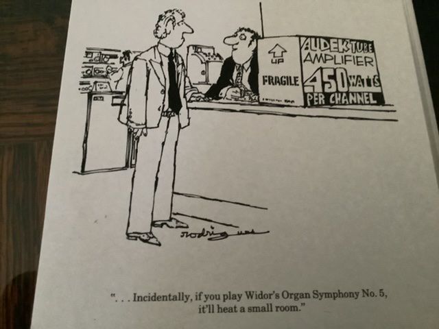
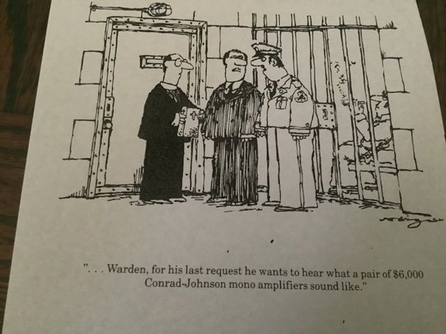
No, I did not see it before. Profuse thanks! I will totally enjoy the cartoons while having lunch today!!! Maynard
-
The purpose of the screen stopper is not to reduce the voltage relative to the plate. In tubes which permit the same voltage on the plate and screen, this is unnecessary. Rather, in combination with the internal capacitance of the tube, it forms a RC filter to reduce the possibility of unwanted (parasitic) oscillation which occurs with some pentodes when used as a triode. Tying the plate and screen together, by increasing the surface area of the elements , also allows a slightly higher plate dissipation if someone wants to extract every last bit of power from the tube. Maynard
-
Henry asked for my opinion about sharing a cathode resistor between the two output channels. Well, I have never tried it! I imagine it would result in a little crosstalk between the channels which, depending on the result one is looking for, may not be bad in that it could provide a tighter center image than dual mono would provide. It may be similar to using a shared B+ rail to feed both output xfmrs ( there was a big discussion about this on DIY audio maybe 8-9 years ago which I will try to find). Another consideration is what would happen if one tube gets weak or craps out. Remember, the value of the shared cathode resistor is half of that for a single channel. So, if the current through it decreases significantly, the bias will be off. For the minimal difference in cost, I don’t see the point of not using separate resistors and caps. Regarding AC vs. DC input coupling, I have always favored the former after encountering devices with leaky output coupling caps spilling DC. Also, my preferred driver is a grid leak biased triode which, of course, requires AC coupling. The 6SJ7 can be biased that way as well although I have not yet tried it that way. If anyone wants to build but finds chassis prep to be more than they want to tackle, the Spudkit may be a nice alternative. Spud amps have the advantage of only using a single amplifying device per channel. I have done a lot of work with pentode and triode spuds and elimination of a driver tube can result in some amazing sound, especially if speaker impedance variations are controlled in the pentode units (a 27 ohm resistor across the speaker terminals is all that is needed). https://spudkit.com/ Enough rambling for today (my wife thanks Henry for convincing me to spend a few minutes on here- she thinks I don’t have enough to do 😬 Maynard
-
Given what people are charging for copies of that book, how about posting a few cartoons a day so all can enjoy the incredible humor? Maynard
-
I was referring to the schematic Nick posted at the start of the thread. I’m not getting that old😃 Maynard
-
Nick, can you post your load line drawn on the triode plate curves? I can’t imagine getting more than a couple of watts from a 6L6 at the operating point you specified, and would venture that the distortion would be upwards of 8%. Thanks… Maynard
-
Have you run older 6BG6s at much over 19 watts dissipation without issue? If wanting to do that I recommend picking up some Phillips 6BG6GAs from Mike Marx at SND tube sales. They are truly equivalent to the 6L6GC and will run at 30 watts dissipation all day without issue. Maynard
-
For those who like the 6BQ5 or EL84 go with a 6GK6 which can be purchased NOS for about $8. It is electrically identical but with a different pinout and was used in many tvs. You can even go with a 16GK6 for about $3! Maynard
-
Rodrigues was a genius! Maynard