Curious_George
-
Posts
1137 -
Joined
-
Last visited
Content Type
Forums
Events
Gallery
Everything posted by Curious_George
-
I have used a 4x multiplier for many years and never had a resistor fail.
-
Type AA crossover rectangular capacitor replacement
Curious_George replied to Tizman's topic in Technical/Restorations
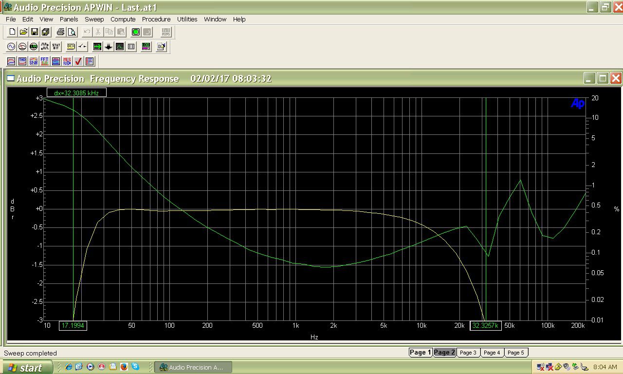
Holy Bat Graph! -
Type AA crossover rectangular capacitor replacement
Curious_George replied to Tizman's topic in Technical/Restorations
Those constant "k" filters were not the best for audio filters, but they worked in the Heritage line for a long time. -
Type AA crossover rectangular capacitor replacement
Curious_George replied to Tizman's topic in Technical/Restorations
Please post... -
Type AA crossover rectangular capacitor replacement
Curious_George replied to Tizman's topic in Technical/Restorations
Well I'm willing to help if anybody needs assistance if my knowledge and experience are suitable for said subject of help needed. -
Type AA crossover rectangular capacitor replacement
Curious_George replied to Tizman's topic in Technical/Restorations
Butterworth for the values previously posted. Bessel - 1.65uF / 0.18mH / 8.24uF = 6000 Hz @ 8 (impedance) Today, if you have some technical or even computer skills, most hobbyist can use DATS to measure impedance and REW for room measurements. Both DATS and a good microphone for REW will only set you back $250. Not a lot of money for very powerful tools if you are into speakers or the DIY speaker hobby. If for some reason, you are not skilled, there is always another hobbyist willing to help. -
Type AA crossover rectangular capacitor replacement
Curious_George replied to Tizman's topic in Technical/Restorations
2.22uF / 0.21mH / 6.65uF = 5200 Hz @ 9.2 (impedance). This is what the filter would be doing "electrically". Acoustically is a different matter and what really counts because you want a smooth transition (frequncy response) to your other drivers. If you know the impedance of your tweeter at the desired crossover frequency, you can "easily" (yes, easily...) calculate your new crossover point. You can use many online crossover calculators to tweak your AA tweeter section. -
.
-
.
-
.
-
.
-
Type AA crossover rectangular capacitor replacement
Curious_George replied to Tizman's topic in Technical/Restorations
The first thing that comes to mind is cyanoacrylate (AKA - super glue). It flows well into tight spaces and comes in different viscosity. Buy some from a “model shop” and you should be able to choose thin, medium or thick. Medium would probably work best. -
Type AA crossover rectangular capacitor replacement
Curious_George replied to Tizman's topic in Technical/Restorations
I like your sarcasm Henry. I too get irritated hearing asinine responses from “the experts” on here sometimes. But what are we talking about… only a few people here are worthy to build crossovers. No to mention designing them which even fewer people can do. -
Type AA crossover rectangular capacitor replacement
Curious_George replied to Tizman's topic in Technical/Restorations
As indicated, replace the caps, but the inductor and autoformer should be ok to reuse. The aren’t pretty anymore, but if for some reason you do replace them, PM me and I’ll buy them. -
How about simulating a WE417a/5842 or Sovtek 6C45P. These are popular too for SE amps.
-
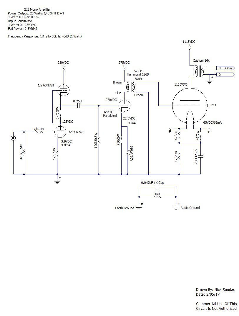
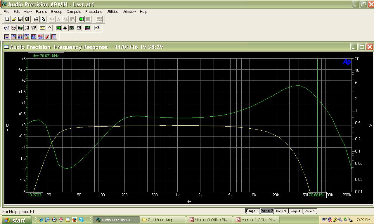
Yes, I am familiar with it. The Ongaku was my inspiration when designing my original circuit. Then, as time, money and experience allowed, I designed the 6BX7 driver circuit. Having 16kohm output transformers with decent bandwidth has been a great asset. They were custom made back in 2000.
-
In a 2 stage DHT amp, you can take advantage of the 2 stages by trying to "balance out" the 2 triode stages since they are out of phase. Trying different operating points for each stage can cancel distortion products significantly sometimes. It is a "freebie" and those are rare.
-

-
Some history of my 211 driver circuit; I initially built the 211 mono amps back in 2000. At the time, I did not have a lot of disposable money, so I designed a budget driver circuit. All the major components were already adding up and a 45 or 300B to act as drivers were not an option. I wanted to design something original anyway and did not want to just copy a circuit from the Internet. I have always ahd a fondness for the 6SL7 and it seemed to have enough gain for the purpose of driving the 211 in Class A1 to about 15 watts, which was fine for me at the time. I had plenty of power supply voltage so the 6SL7 (paralleled) was going to have a nice "swing". I direct coupled the 6SL7 to a 6F8G (paralleled also, similar to a 6SN7). This circuit worked great for a long time, until I wanted to see what Class A2 would look like with a different driver. Since my 211 chassis already had 2 octal socket holes, I pondered different tubes to use so I would not have to add new holes to my chassis. I also wanted to be able to use 6.3VAC filaments since my previous circuit used 6.3VAC too. There was also a current limitation for the 6.3VAC tubes as well. Retro-fitting always involves compromises if you want to preserve something. In this case, my chassis and look of the amp. I did not want it to look like a giant bench experiment. I also did not want a lot of gain since 2 tubes were going to be cascaded. My tube options were limited, but I finally came up with a circuit that appeared to meet my needs using octal sockets and the right filament voltage/current. An SRPP 6SN7GT coupled to a 6BX7GT (paralleled) with interstage transformer. This circuit will easily put out 100VRMS with fairly low distortion.
-
If you add the anode resistor to U1, you can tweak the final distortion, but it is negligible. I'm sure you know that. Most people omit that resistor including me.
-
Here is the current driver circuit for my 211 amp. I didn't simulate it, I designed and built it. I never put in the time to learn LTSpice, but maybe soon. I've used other "Spice" type programs, but not LT. I'm sure it is fun, but there never seems to be enought time in a day to get all the fun in!
-
I think it is poular because it has been on the Internet for 20 + years. I always use a preamp with my tube amps, so I would never use this much gain in the front-end unless I was using a little feedback. However, I would not use this circuit for high gain. I would use another.
-
Can you switch between 211 and 845 tubes in your amp? In other words is the amp designed for both with the ability to flip a switch and use either tube? I’ve been wanting to convert my 211 amp to use both, just too many other projects. Perhaps soon.
-
You may want to try CLR too.
-
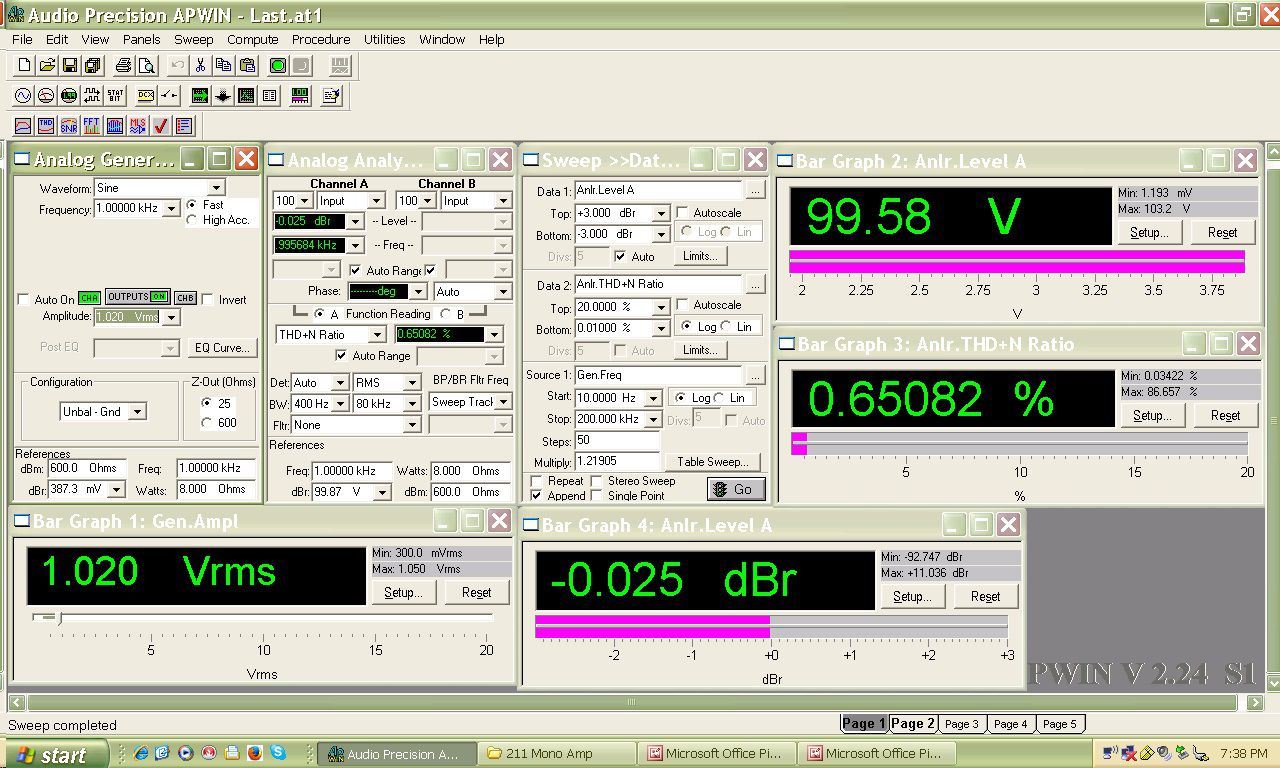
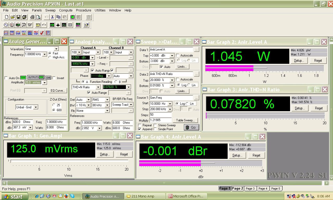
I am using a 6BX7GT (in parallel) with an interstage transformer as a driver for a 211 tube and it performs great. Pushes the 211 way into A2 no problem. I am getting 25 Watts out @ 5% THD+N. Not quite like a 2A3 or 300B, but that BIG DHT triode sound. Sounds great to me.