


mboxler
-
Posts
574 -
Joined
-
Last visited
Content Type
Forums
Events
Gallery
Posts posted by mboxler
-
-
I built an AA for fun...sounded terrible.
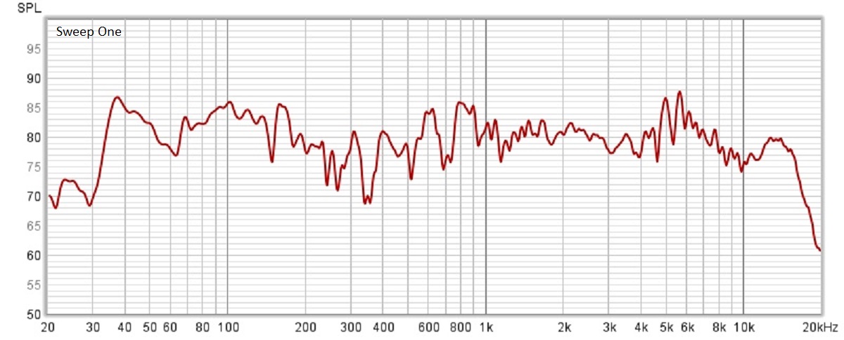
The sibilance on my K-33E/K-55M/K-77M Khorns drove me out of the room. I couldn't find a crossover error, so I set up my mic and ran some REW sweeps.
Sweep One below shows a large dip between 300 and 400hz, and a large bump between 5 and 6khz.
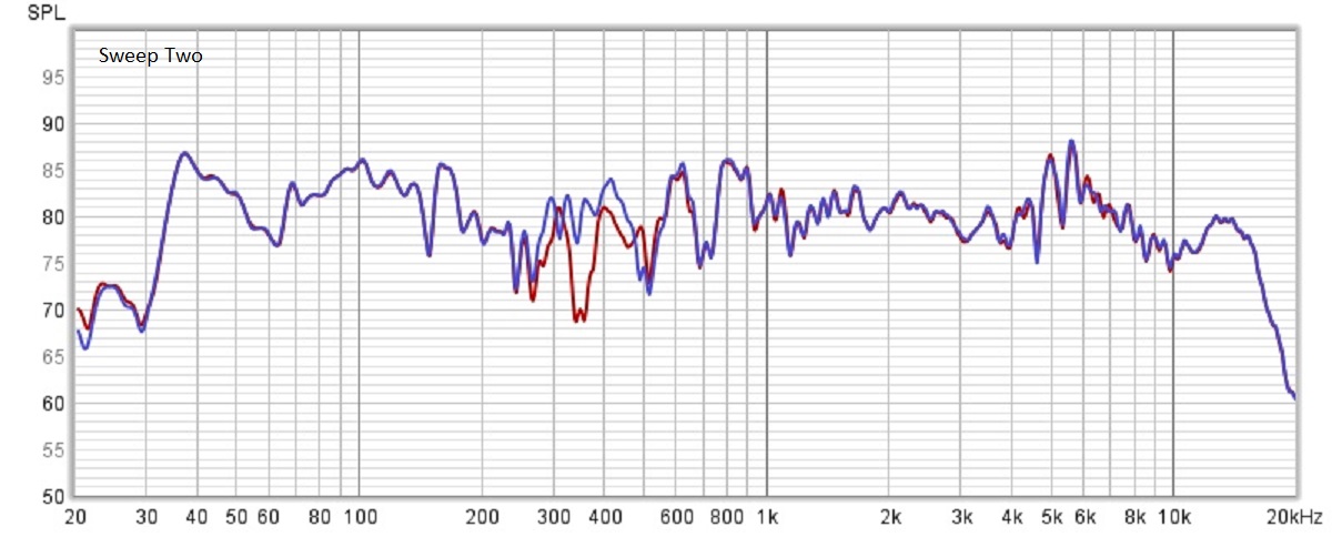
In Sweep Two below, I reversed polarity on the woofer. The blue trace shows that the dip is gone. Is this the K-55M phase shift issue the AK-3 corrected???
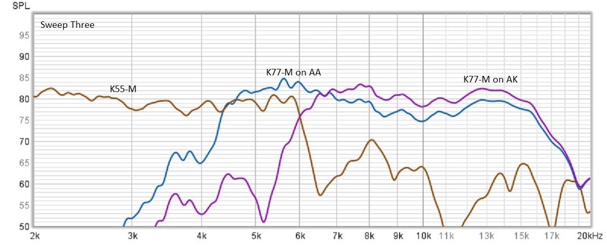
Sweep Three below explains the bump between 5 and 6khz. The K-55M is fairly flat to 6khz, then drops. The AA tweeter on the K-77M crosses the K-55M around 4.5khz.
I have an AK type tweeter filter, so I put an 8 ohm resistor across the AA tweeter out, and connected the AK tweeter filter between the amp input and the K77-M. As you can see, the AK filtered K77-M crosses with the K55-M perfectly at 6khz.
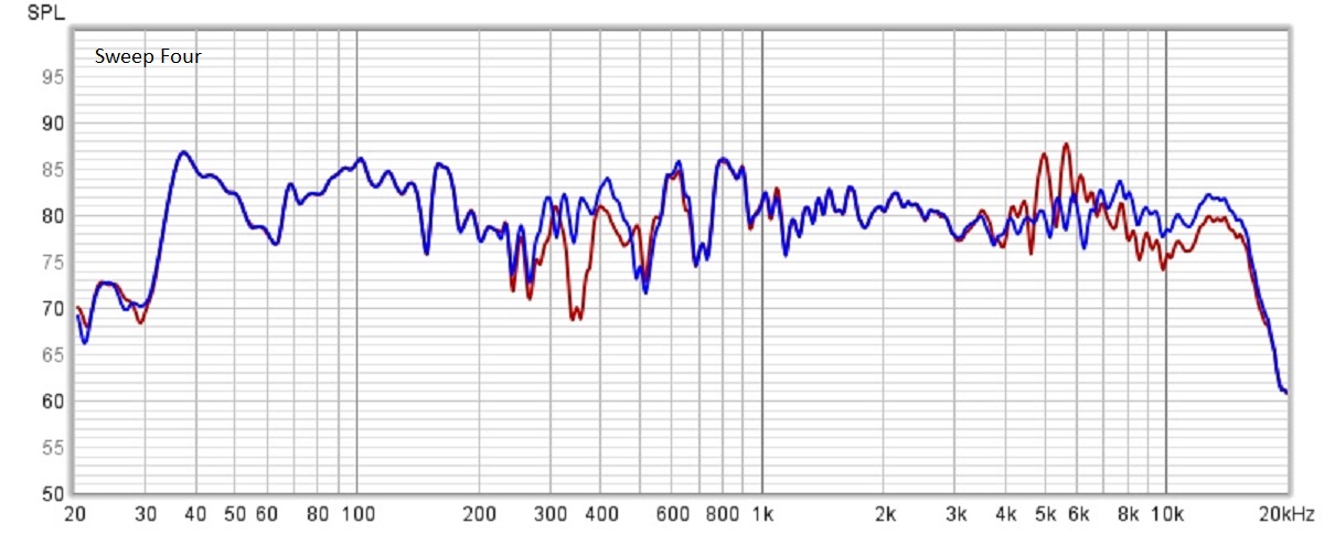
Sweep Four shows the AA (red) vs the "AAK" (blue). Not bad!
Does the K-55V drop off sooner than the K-55M? If so, was the AA tweeter filter designed to compensate for that drop off?
Oh...my Type "AAK" sounds pretty good! Still some sibilance but nothing like it was with the AA tweeter filter.
Thanks, Mike

-
 1
1
-
 1
1
-
-
10 hours ago, jeffyd89 said:
I was a little worried but now that I see some1 else have the same resistance reading I'm a bit relieved. Looks like I'm just going to add the 2ohm resiters to the high side and throw her back together. It just socks because I sized the amp for an 8ohm load [denon poa 6600] and now I think I need to make a change
A speaker's ohm rating is a nominal rating. In reality it can bounce all over the place. If the nominal rating is 8 ohms then you should be fine.
Just to be clear, your DMM is only measuring the resistance of all series inductors plus the series voice coil they are connected to.
The tweeter circuit contains a series capacitor (which blocks DC), so on it's own it will measure as an open circuit with or without the 2 ohm resistor.
Since the RF7's woofers are wired in parallel, that measurement will probably be half the value of either woofer circuit on it's own.
This is why your measurements with the straps are equal to the woofer terminals without the strap. The tweeter circuit measures as if it's not there.
Mike
-
1
-
-
1 hour ago, OO1 said:
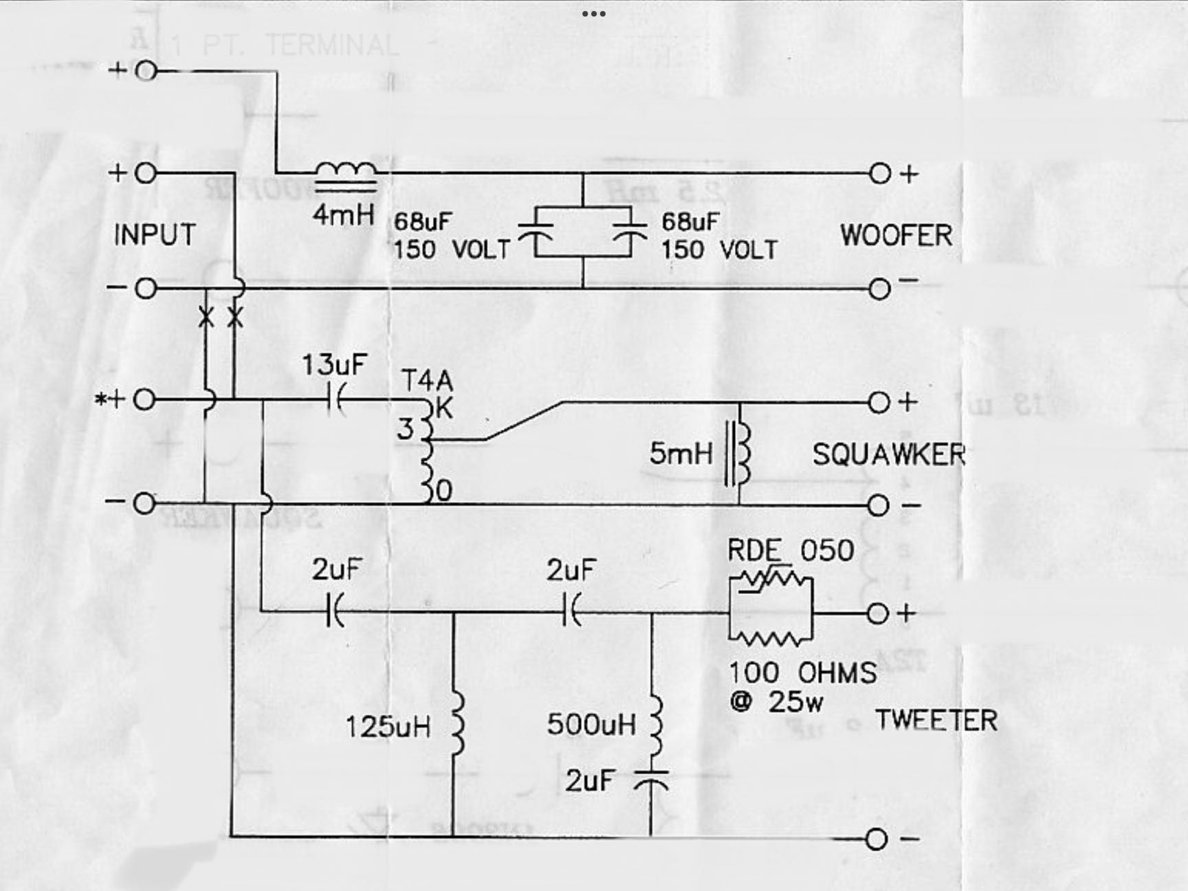
I've never seen a E2 with metal cans before so this could very well be a modified E network , the E2 usually ship with small black caps instead of cans
the E2 woofer inductor is 4mH whereas the E is 2,5mH.
My E2 networks. Notice the stamped 2 next to the E and the metal cans.
-
14 minutes ago, jcn3 said:
That cap is across the woofer and is what makes it an E-2 (along with the inductor change). Don't know why the crossover is mismarked.
I've always assumed that as they were transitioning to the E2 there were still a lot of E labels on hand. My E2 network had an E label and the number 2 was stamped next to the E with no color.
-
1
-
-
4 minutes ago, Edgar said:
I love it when science works!
However, make certain that your AC resistance measurements are not also including the inductive reactance magnitude.
I'm assuming it doesn't since the reactance of a 245uh inductor is 15.4 ohms at 10 khz.
-
1
-
-
1 hour ago, Edgar said:
The change is measurable. The specific cause(s) of the change are unknown without more information.
However, magnetic hysteresis consumes energy and dissipates it as heat. That means it acts like a resistance. Resistance in an LC circuit reduces the Q, i.e., flattens-out peaks. It's only conjecture, but it seems to fit.
I believe your are correct. My 245uh air coil measures .1 ohm DCR. When I switch to resistance at 1 khz, it is .152 ohms. Placing the nail through the center increases the resistance to .524 ohms.
Likewise, at 10 khz, the resistance increases from 1.75 to 3.59 ohms.
In either case, Q is almost cut in half with the nail, which will flatten the peak.
Mike
-
8 hours ago, Travis In Austin said:
How much smoothing do you have going on there? Do you have the raw (dirty) curves?
No smoothing. This is as dirty as it gets.
8 hours ago, Travis In Austin said:In terms of speaker design and XO configuration (without regard to what part is doing what), which of those three is best? If someone showed you mBoxler's 3 curves, and said "here are three different parts, cost is equal, pick the one you want". Which do you pick? Red looks like a 4800 kHz XO, Green looks like a 4900 XO, and Blue looks like 5500 kHz XO. All three look to have the same slope. I guess you can't tell slope from curves like that? An octave lower would, on average, be about 2500 kHz and the drop is 16 to 20 dB per octave depending on which of the three. Maybe these curves are just the inductor, Not the XO as a whole and so slope can't be determined?
This is the actual voltage across the K-77M. All of them start out around 18db per octave. The slope steepens up to the peak voltage point. I think this is due to the fact that this is an underdamped high pass filter???
Mike
-
1
-
1
-
-
43 minutes ago, Edgar said:
One of the curves is measured while the other is simulated using LTSpice.
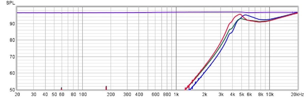
This confused me 🤔. Luckily, I found a 245uh and a 345uh inductor, so I ran tests across a K-77M.
The blue plot is a 245uh inductor.
The green plot (little hard to see) is the same 245uh inductor with a nail through the middle to bring it up to 345uh.
The red plot is an actual 345uh inductor.
Surprised me to find out that the 245uh plus nail isn't even close to the 345uh!
Mike
-
1
-
1
-
-
2 hours ago, Travis In Austin said:
I guess I really even need to learn something more basic. Does the air core inductor, in that circuit relate to what the XO frequency will be. (If so, is that because it is acting as a low pass filter, only allowing frequencies abound a certain number, pass to the tweeter). Or maybe It’s doing none of these, or all of them.
The shunt inductor on the AA tweeter circuit controls the amount of current passing through the driver. It's impedance increases with frequency. It's really acting like a high pass filter.
As frequency decreases, more current will pass through the shunt inductor, and less current will pass through the driver.
As frequency increases, less current will pass through the shunt inductor, and more current will pass through the driver.
The larger the inductor, the sooner in frequency the current across the driver will peak.
2 hours ago, Travis In Austin said:Is there a corresponding high pass filter in the Squawker XO circuit?
Yes...it's the T2A autoformer, which is a 21.2mh inductor across the squawker.
-
1
-
2
-
-
6 hours ago, Rolox said:
It is still unclear in my head how ALK manages to have so many different outputs on a 3619 when the input connections are fixed. Does that mean with a 3636 I could actually get MORE attenuation possibilities than the announced 1dB steps from -1dB to -12dB (sorry I'm still using dBs because I just don't know how to calculate the ratios), possibly in-between steps as well?
You can get 26(?) possibilities with the 3636 when the inputs are on taps 5 - 0, and 15 possibilities with the 3619.
6 hours ago, Rolox said:Sorry if I ask dumb questions, I've been using autoformers in my crossovers seemingly forever, I mean for as long as I've been playing with big Klipsch and now with similarly "horny" speakers - but I've never really wondered how those actually work, not in details at least.
Thanks! 🙂
No need to be sorry. We're all learning. If it weren't for LTspice, I never would have fully grasped how autoformers work.
I'm having trouble finding my docs for these, but if you go to Al's website under Universal Economy, and scroll to the bottom of the page, you'll find the 3919 tap settings. Think of the left value under Ratio as the output voltage if the input voltage is 1 volt. Plug those two values into this calculator to get the attenuation in db. For example, input 1 volt output .6452 volt results in -3.8db if the output taps are 2 - 5.
http://www.sengpielaudio.com/calculator-amplification.htm
Hope that helps!
Mike
Mike
-
1
-
-
6 hours ago, Klipschguy said:
So, the reflected impedance of the T2a tap 3 does not affect the crossover value required in the tweeter leg??
The AA tweeter circuit will change the load, but not significantly. I think the voltage across the squawker will gradually drop by another 3db or so around 5000hz compared to the stock filter.
6 hours ago, Klipschguy said:I know the tweeter leg of the HIE and the AA bypass the T2a.
Actually, since the tweeter circuit is attached to tap 5, the T2A isn't really bypassed. In this case, it functions like a 45mh inductor. Therefore, at very low frequencies, the AA tweeter filter is actually 5th order (30db per octave). However, because the inductance of the autoformer is so large, it gradually turns into a 3rd order filter at higher frequencies. Your "Type EE" crossover will behave in a similar way.
I always wanted to build a "Type EE" network. Go for it!
Mike
-
2
-
-
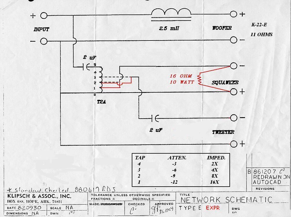
Once you get away from labeling the taps "db", it becomes clearer.
Each tap connects to a specific winding of the autoformer. The ratio of the input connection to the output connection dictates the voltage change. On a T2A, the ratio of taps 4 - 0 to 5 - 0 is .68, so the output voltage is 68% of the input voltage, or -3.35db.
There is no reason why one can't connect the input to 5 - 1 (75% of the windings) and the output to 4 - 1 (43% of the windings). .43 / .75 = .573, so the output voltage is 57.3% of the input voltage, or -4.84db.
Since the T2A exposes only four of the internal windings, the number of input to output ratios is limited. The other autoformers allow access to more windings, and therefore allow for more input to output ratios.
Yes you can swap any autoformer with any other autoformer on your crossover, as long as you realize that each will have unique attenuation possibilities.
Mike
-
3
-
1
-
-
8 hours ago, Rolox said:
I'm doing it, with a pair of ALK original "Universal" networks. I just bypassed the coil in line with the woofer and connected the crossover inputs straight after it to the rest of the network that deals with the mids/high crossover. Works pretty well and the various taps on the auto former allow me to further dial in the midrange with the rest.
Just to clarify, if your active crossover contains a low pass to the woofer AND a high pass to the crossover, you should connect your high pass amplifier to the crossover RIGHT AFTER the crossover's 48uf(?) capacitor.
Mike
-
5 hours ago, MacWorks said:
Do I need to look for the same Type B or can another type be used?
I believe the B2 is an upgrade of the B???
If this is the case, just add three components to the B to get a B2, and it could be easily reversed if you don't like it...
Mount a 20uf capacitor across the woofer outout.
Mount a 245uh inductor across the tweeter output.
Mount a 12uf capacitor in series with the B's 4uf capacitor to get to the B2's 3uf capacitor.
Reverse the polarity of the squawker and tweeter outputs, and give it a listen.
Just a thought.
Mike
-
2
-
-
13 hours ago, Peter P. said:
So 'splain something to me: A wireless DAC will allow me to stream audio from my Mac to the DAC, which I can plug in to any RCA input on my amp?
Say I want to stream youtube audio from my Mac to the stereo via the DAC- how does the Mac know to send the audio via bluetooth? Does the Mac
doe this by default?
Do I need to pay big bucks for one of these wireless wonders? Recommend me something.
It would be nice to push the Mac's audio through my Heresy's vs. the tiny built-in speakers.
Are you referring to a Bluetooth adapter with RCA out to a preamp like this...
I don't do this, but here's a link that may help...
Mike
-
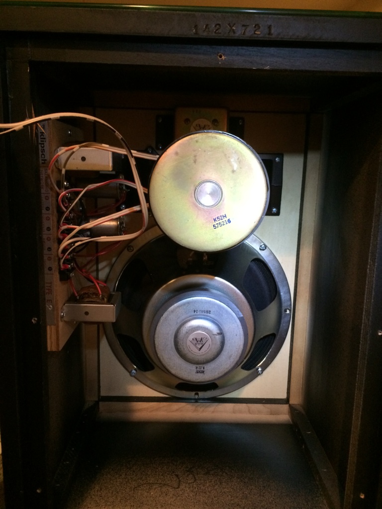
I decided just to rerun the AA test using a K55M and K77M.
I had forgotten that the AA tweeter circuit actually dips down to around 5 ohms at 5000hz before quickly bouncing back. That results in the sudden voltage increase across the K55M at that frequency.
At the point before this increase at around 5000hz the voltage across the K55M is down around 6db.
Mike
-
1
-
-
I am curious how others define attenuation. Yes, the voltage on Tap 4 of a T2A is 3.35db lower than the voltage on Tap 5. And the voltage on Tap 3 of a T4A is 4db lower than the voltage on Tap K.
However, unlike the AA, the tweeter circuit of the AL-3 is separated from the squawker circuit. With the AL-3 circuit, the voltage across the squawker increases with frequency until it levels off at -4db. This is the amplifier voltage minus 4db. This is because the load on the 13uf capacitor is fairly constant from 300hz on up.
With the AA, the parallel tweeter circuit affects the load on the 13uf capacitor. Like the AL-3, the load on the 13uf capacitor is fairly constant UNTIL the impedance of the tweeter circuit drops enough to affect the parallel impedance of the squawker/tweeter circuits. As a result, the voltage across the squawker rises to around -4.5db then levels off as the load on the 13uf capacitor steadily drops to around 8 ohms. Again, this the amplifier voltage minus 4.5db.
In other words, I believe the AA attenuates the squawker more than the AL-3??? I think I've tested this before. If not I may have to test it again 😎
Mike
-
1
-
-
11 hours ago, geoff. said:
Question 1:
Is 13uF the correct value for the T4A with 4db of attenuation? From another post (by DJK) the correct value was calculated at 10.36 uF. So would a 10 be more appropriate than a 13?
Without a link to DJK's post, I can only make an uneducated guess as to how the 10.36uf value was reached.
If you assume that Tap 4 on the T2A is -3db, then the reflected impedance would be 2 times the impedance of the K55.
Tap 3 on the T4A is -4db, therefore the reflected impedance would be 2.51 times the impedance of the K55.
2 / 2.51 = .797. .797 * 13 = 10.36.
In reality, tap 4 on the T4A is -3.35db, and the reflected impedance is 2.16 times the impedance of the K55
2.16/2.51 = .86. .86 * 13 = 11.19.
In reality, the AL3 and AA filters are completely different, so I'd leave the 13uf as is.
11 hours ago, geoff. said:
Question 2:
Why is the tweeter coil value (125uh) between the same two 2uF capacitors in the AL-3 half of the value of the coil in the AA crossover (245mH)? If I run the AL-3 without the elliptical filter would their be a more appropriate coil value?The reason I ask is I recently built a pair of AL-3s, and a pair of AAs, with some cheap ERSE polyester caps I’ve had sitting on a shelf since before everything doubled in price and I was surprised to find I preferred the AAs over the AL-3s, apples to apples. I was not expecting that.
My first experience with La Scalas was with a pair having the AL-3s and what’s left of my memory recalls them being all that and a bag of chips. But this time around my brass ears found the AL-3s a little reserved. Like there was a hole in lower midrange/upper bass.
I should mention these crossovers are in (on top of for now) LSI Splits with K-43 woofers, K-55M squawkers, and a variety of tweeters floating on top. I removed the grab handles and stuck a barrier strip on top of the opening for fast changes. Internal driver wires to the bottom and crossover wires to the top.

The 125uh value is needed to compliment the deep notch in the elliptical filter. If you remove the deep notch and leave the 125uh inductor as is, the transfer function across the tweeter will be a little shallower and peak later than with the 245uh of the AA.
Mike
-
1
-
-
2 hours ago, geezin' said:
OK back on topic. Cannot remember where I found this but can someone explain what it is and why to do it? Is it a factory thing?
This mod reduces the voltage to the squawker and tweeter an extra 3db each. However, moving the squawker and tweeter taps doubles the load on the shared 2uf capacitor. This actually results in a voltage "bump" across the squawker before settling down to the new desired attenuation. The purpose of the parallel resistor is to cut the new load in half, pretty much back to where it was in stock form. The resulting transfer function is now down the extra 3db at all frequencies.
-
Now that I think about it, I'd just use the 4mh from the AK-2. The difference would be minimal.
-
1
-
-
10 minutes ago, Tom05 said:
Yes , I’ve got a set of AK2’s that I’d eventually like to convert to AK3 . I bought the 3636 a few years back , never got around to doing the conversion . I see the 5mh across tap 3 what does that value need to be?
If you want a transfer function similar to the Klipsch AK-3 with the T4A, a 3.5mh inductor should be used with the 3636 across taps 0 - 3.
-
1
-
-
24 minutes ago, Tom05 said:
Great thread, (as others have also pointed out )you guys sure are knowledgeable . Curious about the universal autoformer crites 3636 can it be used as an accurate substitute for the T4A ? Your post makes me question its use . I was under the impression that T4A was no longer available .
You can get pretty darn close. The inductance between taps 0 - 3 on the 3636 is roughly 20mh. The inductance between taps 0 - 3 on the T4A is 7.3mh. On it's own, a 11.5mh inductor across tape 0 - 3 of the 3636 will bring it's inductance down to the T4A level. If you are using it for an AK-3 crossover, the 5mh inductor across taps 0 - 3 of the T4A gets you 3mh of inductance. If you place a 3.5mh inductor across taps 0 - 3 of the 3636, you end up with the same value. Is this for an AK-3 crossover?
-
2
-
-
18 minutes ago, tigerwoodKhorns said:
Silly question but for someone who already has polypropylene caps, can you run a parallel 0.5 ohm resistor on the existing caps? I found this at Partsexpress but am curious about something that might be less expensive from Digikey or a similar source:
Are you trying to add resistance to the capacitor to simulate ESR? If yes, then the resistor would need to be in series, not parallel. Unfortunately, ESR changes with frequency. I have a 2uf polyester cap that measures .31Ω ESR at 1000hz but .06Ω ESR at 10000hz.
-
2
-
-
1 hour ago, Deang said:
These measurements directly influence the voltage curves and transfer function. This much I learned directly from Roy, which is why he asked me to use Tecate, and to have Universal Transformer bring back the T2A, T4A autoformers and various coils. I even had to request a certain steel type for the laminations, as these also effect the voltages.
Well, I'm out. I no longer have the emotional bandwidth for this.
I respect your decision to opt out, so can someone please define for me "transfer function" as it relates to Klipsch components? I always assumed it was the voltage curves across the driver attached to a crossover when doing a frequency sweep. I've been using REW and a Focusrite Scarlett Solo. However, when I Google "transfer function", I get complex mathematical equations.
Are voltage curves and transfer functions the same thing?
Thanks, Mike

Type AA plus K-55M/K-77M = Sibilance?
in Technical/Restorations
Posted
Thanks, I forgot about that thread. Looks like the K55V single phase plug drops off quite differently compared to the K55M.
Dean's right...I gotta stop measuring stuff.